D. Parsons,^ T. Kazmierski^ o Southampton Institute of Higher Education, East Park. Terrace, Southampton SO9 4 WW, UK. * University of Southampton ...
Transactions on Engineering Sciences vol 3, © 1993 WIT Press, www.witpress.com, ISSN 1743-3533
Object oriented schematic capture for circuit simulation D. Parsons,^ T. Kazmierski^ o Southampton Institute of Higher Education, East Park Terrace, Southampton SO9 4 WW, UK * University of Southampton, Southampton SO9 5NH, UK
ABSTRACT The development of an HCI (Human Computer Interface) for circuit simulation software is an appropriate area for the exploitation of object technology. This paper describes how an object oriented graphical user interface is being developed to provide a schematic capture facility for the Alfa object oriented circuit simulation language. INTRODUCTION In approaching the issue of an appropriate paradigm for a schematic capture interface for circuit simulation, a number of issues are raised. Firstly, few programmers can approach the writing of any kind of WIMP interface in the current climate without acknowledging the firm establishment of object technology in such programming applications. Since the development of Smalltalk for the Dynabook project at Xerox PARC [1], object technology has become the norm for graphical interfaces. Secondly, the nature of the software engine behind the interface must have a bearing on the way in which the semantics of the interface are designed. In this particular case, the interface is intended to provide input source code to the Alfa simulator. At the present time, the link between the interface and the simulator is via ASCII file, but the potential for closer integration is a factor in attempting to make the two applications semantically compatible.
Transactions on Engineering Sciences vol 3, © 1993 WIT Press, www.witpress.com, ISSN 1743-3533
378
Software Applications in Electrical Engineering
The long standing relationship between simulation applications and object technology is well known, and dates from the development of Simula67 [2]. It is not within the scope of this paper to discuss the detail of the simulation language, Alfa, which lies behind the schematic capture interface, suffice to say that the application of the object oriented paradigm to its methodology is crucial to its approach. Alfa itself has been documented elsewhere (Kazmierski, Brown, Nichols & Zwolinski [3]). In the light of the above, a schematic capture interface for Alfa is currently under development using C+ + [4]. This is clearly the most appropriate language to provide compatible links with Alfa, since it is the language into which Alfa is parsed, and shares much of its syntactical style. It also has the advantage of providing portable executable code without the environment overhead of, for example, Smalltalk. THE CIRCUIT DOMAIN Unlike many data processing applications, the area of circuit simulation provides an environment within which the identification of "objects" is blindingly obvious. This is a great advantage when approaching an application from an object technology viewpoint. A circuit simulator interface must be as representative as possible of the physical process of building the circuit in reality, and a programming paradigm which supports the one-to-one relationship between real world objects and software entities has to be advantageous. The circuit domain is comprised of discrete objects, passing messages between each other. Such a domain appears therefore to be an application area in which object technology can bear fruit. ABSTRACTION AND OBJECTS The abstract data type is an important tool of object technology, allowing as it does the essence of each object to be represented in a "template" of attributes and methods. Thus the C+ + "class" acts as an abstract data type for each object in the system, standardising state attributes and behaviour methods across a class of objects. When representing electronic circuit components in software, the object oriented approach allows each component to be modelled as an abstract data type, linking together a number of generic characteristics of each component. These include: 1.
The visual image of the component on the screen
2.
The attributes of each component type (e.g. Resistance for a resistor)
3.
The relationships between the component and other objects in the circuit
Transactions on Engineering Sciences vol 3, © 1993 WIT Press, www.witpress.com, ISSN 1743-3533
Software Applications in Electrical Engineering
379
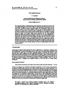
Each specific component object which is dynamically created in the system is therefore capable, by containing state values for the generic attributes, of linking together these aspects so that an individual component is able to display itself on the screen, and also relate its external interfaces to the interfaces of other components and nodes. By tracing through the components in the system at any one time, each object is able to contribute to the Alfa source code which is written to disk by the interface for input into the Alfa simulator. The data which is required of each component in the circuit is the ability to report its own unique name, generated when the object is created, the value(s) of its attribute(s), and the names of components or nodes to which its external interfaces connect. Nodes are required only to return their unique names. In both cases, the system creates unique names by utilising class member functions; one which returns the generic name of the class (e.g. CAPACITOR, XORGATE etc, and another which uses a static data member (i.e. only one variable for the whole class, rather than one per object of the class) to keep a count of how many objects of the class exist in the system. By combining the name of the class with an instance counter, a unique object name can be created. For example, the first capacitor in the system will be called CAPACITOR_1, the second CAPACITOR 2 and so on. Nodes are named NODE_1, NODE 2 etc. (ref. Alfa source code, Figure 4). COMPONENT HIERARCHIES In addition to the use of abstract data types to model components, object technology offers the ability to create classification hierarchies of generic component types. This allows duplication and redundancy of data and functionality to be eliminated, whilst ensuring consistency of structure. For example, the several types of resistor need not be modelled entirely separately if inheritance is utilised. The ordinary resistor can be used as a base class, from which other types of resistor with additional functionality may inherit. Therefore we may build on the attributes and functions of the Resistor class to create Photo-resistors, Thermo-resistors, VDRs or any other resisting device. Figure 1 below illustrates the principle of the inheritance hierarchy in terms of the screen images of three resisting devices. The Photo-resistor and Variable Resistor classes inherit their base image from the Resistor class, but add additional elements. Internally too, the attributes of the Resistor class are inherited and built on by the derived types. Inheritance also allows generic messages to be sent to all objects in the hierarchy, regardless of their specific class type. When an object is sent a message, for example, to draw itself on the screen, it knows how to create its image via a function unique to the class, but with a name shared by all classes in the hierarchy. In C+ + , such "polymorphic" methods are facilitated by the use of "virtual" functions.
Transactions on Engineering Sciences vol 3, © 1993 WIT Press, www.witpress.com, ISSN 1743-3533
380
Software Applications in Electrical Engineering Resistor
A
PhotoResistor
Variable Resistor
Figure 1: An inheritance hierarchy of resistor devices
We may examine how such a hierarchy can be utilised in C + + by describing how the devices are drawn. Firstly, the Resistor class allows an object of the class to draw itself on the screen using the drawQ member function which utilises simple graphics library functions: void Resistor::drawQ { line(x + vect[0], y + vect[l], x + vect[2], y + vect[3]); // etc....
A photoresistor needs to be shown with the same visual image, but with the addition of two arrows. Because the Photoresistor class inherits from the resistor class, the member function drawQ of the base class can be called from the member function drawQ in the derived class. void Photoresistor::drawQ // The base class version of drawQ is called first Resistor::draw(); // Then the arrows are added line(x + vect[0], y + vect[l], x + vect[2], y + vect[3]); // etc.... }
Transactions on Engineering Sciences vol 3, © 1993 WIT Press, www.witpress.com, ISSN 1743-3533
Software Applications in Electrical Engineering
381
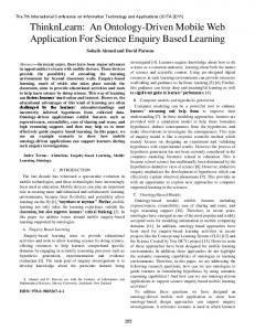
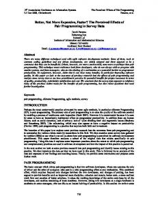
Note that in this case, the array vect[] has been declared as a private attribute of both the Resistor and Photoresistor classes. Because the array vectf] is therefore seen separately by the constructors of the two classes, there is no problem in vect[l] for example being used in two contexts. This ensures that there is no accidental corruption of data related to the base class. Other attributes are however inherited without being re-stated, such as the screen coordinates of the two node connections of the component, and the resistance value. By extending the interface, the user may theoretically build further on the base class to create new types of resistor, sensitive to new external inputs, or combinations of factors which may be built in to the model. By using inheritance, only the new behaviour need be modelled, again ensuring consistency with the base component. Indeed, we may further exploit the paradigm by introducing "multiple inheritance", whereby a single class may inherit attributes and methods from more than one base class. For example, we could create an abstract base class of a "radiation sensitive component", which would encapsulate generic radiation (e.g. light) sensitive behaviour, and the arrows which are part of the objects' visual image. The base class would not be intended for instantiation, since it is not a specific component, but may provide individual light sensitive components with generic characteristics and behaviour. Figure 2 indicates such a hierarchy, with the abstract class not intended for instantiation (ref single box outline), whereas the other base classes Diode and Resistor act as both base classes for instances of Photodiode and Photoresistor, but may also be instantiated in their own right (ref double box outline). The form of notation used here is loosely based on the Coad/Yourdon notation [5] in the sense that a distinction is made between abstract classes (containers for attributes and methods, but not templates for concrete objects) and those which may be instantiated as objects. A class which is notated only with a rectangular box is an abstract class, and does not represent a useable object at that level of the hierarchy. Boxes which are surrounded by a second, rounded box, represent classes from which concrete objects may be instantiated. These may or may not be base classes for further derived classes and objects.
Transactions on Engineering Sciences vol 3, © 1993 WIT Press, www.witpress.com, ISSN 1743-3533
382
Software Applications in Electrical Engineering BASE CLASSES
Radiation
Photodiode
Resistor
Photoresistor
DERIVED CLASSES Figure 2: A hierarchy of components using multiple inheritance
CONTROL VIA GENERIC CLASSES In the system, all components inherit from the base class "Component", which allows a common term of reference for all components in the circuit. Likewise, "Component" is a derived class of "CircuitObject", from which the "Wire" class (which allows the creation of circuit nodes) also inherits. The data and processes of each component are encapsulated in specific component objects, but the generic component class allows the third element of a system, control, to be exercised over a collection of various and disparate components. Components and nodes may be controlled separately via the classes "Component" and "Wire", but may also be treated as part of a single hierarchy of "CircuitObjects" Such an approach is clearly applicable to the system as a whole, given the appropriateness of object technology to graphical interfaces. Therefore we see two general areas of hierarchy in the system; one which contains interface objects such as menus, dialogboxes, windows etc, and another containing components and the connections between them. Both however inherit from a simple base class which identifies the locations and visibility of all screen entities and therefore unifies control over the whole system via the visual domain.
Transactions on Engineering Sciences vol 3, © 1993 WIT Press, www.witpress.com, ISSN 1743-3533
Software Applications in Electrical Engineering
383
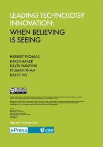
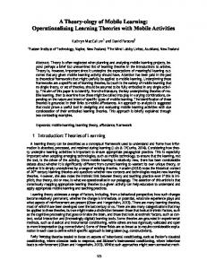
In addition to the use of abstract data types and inheritance, the interface also takes advantage of the facilities of run-time polymorphism via dynamic binding. That is, the system allows component objects to be dynamically created and destroyed at run time, whilst keeping track of them via linked lists of pointers. This ensures that polymorphic (virtual) functions can be called for all components in the circuit via generic component pointers. It is this mechanism which allows all objects to respond to the same message (e.g. drawQ) with individual behaviour. The C++ language provides facilities to instantiate component objects dynamically as indicated above. This allows total flexibility in the number and attribute values of components of any type, constrained only by the size of the addressable memory within which the system can store software representations of component objects. These dynamic objects may include objects created dynamically by the user by defining new subclass of Component or of specific components such as resistors. Abstract classes play a role in the control of concrete objects in term of allowing a generic pointer to be used to locate members of all subclasses. They also play a role in grouping generic attributes from which specific classes may inherit, whether part of the initial system or created interactively by the user. There is a limitation to the use of inheritance which is that it is impossible to remove an inherited attribute from a derived class, only to mask it. For example, a "private" attribute of a base class is inherited but not accessible directly by member functions in the derived class. Private derivation limits the use of inherited elements still further, but there is no method for simply avoiding the inheritance of unwanted attributes or methods. To some extent this implies that the granularity of classes needs to be kept quite small, so that a user-defined type may inherit as little redundancy as possible. AN EXAMPLE CIRCUIT This simple example shows how the schematic capture software allows a circuit to be drawn on the screen, and generate Alfa source code at will. Figure 3 shows a screen dump of the interface, containing a schematic for a simple phase detector. When the circuit is written to file, each object is first asked to return its type, and unique name. This provides the "model mainQ" part of the source code. In the "process flow", each of the declared objects returns its name, followed by a parameter list. This list varies according to the type of component, but in general terms it identifies the names of input nodes, the names of output nodes, and the internal attribute values of the component (if applicable). In the case of the example in Figure 3, source code is created as shown in Figure 4.
Transactions on Engineering Sciences vol 3, © 1993 WIT Press, www.witpress.com, ISSN 1743-3533
384
Software Applications in Electrical Engineering Main ttanu
A 1 fa Schema tic
I
I
M#**#e#: Click l«ft button to *mlmct m#nu or drag box |
Figure 3: Screen dump of Alfa Schematic Capture interface, showing a simple phase detector circuit diagram model mainO Esource ESOURCE 2; Esource ESOURCE 1; XORGate XORGATE 1; Resistor RESISTOR 1; Capacitor CAPACITOR 1; node NODE_4; node NODE 3; node NODE 2; node NODE 1; process flow begin ESOURCE 2(NODE1, Ground, wave2(time)); ESOURCE 1 (NODE 2, Ground, wavel(time)); XORGATE 1 (NODE 1, NODE 2, NODE 3); RESISTOR 1 (NODE 3, NODE 4, 1); CAPACITOR 1 (NODE 4, Ground, 100); end end model main; Figure 4: Source code created by Alfa schematic capture interface
Transactions on Engineering Sciences vol 3, © 1993 WIT Press, www.witpress.com, ISSN 1743-3533
Software Applications in Electrical Engineering
385
The source code, once written, may be used as input to the Alfa simulator. Each reference to a type name in "model mainQ" (e.g. ESource, XORGate etc.) instantiates the component from "models" in the Alfa library, and identifies the names of nodes (also models in the library). A "model" in Alfa is an abstract data type, similar to the class in C + + . The syntax itself is still under development and is therefore liable to modification. CONCLUSION The prototype interface demonstrates that the object oriented paradigm is a powerful tool for the representation in software of electronic circuits. The ability to reflect a concrete real world entity in a software object, encapsulating its own identity, behaviour and knowledge of its relationships with other objects, allows a realistic and robust simulator interface to be constructed. Potentially, the separation of the invocation of Alfa models, and the internal workings of the simulator, give great flexibility in extending the component library, building on existing models to create new devices. An object in the interface need only interact with other objects via its external interfaces (connections), with its internal behaviour encapsulated in an Alfa "model". Ultimately, object technology should be able to provide a more flexible, intuitive and realistic simulator, via a user-friendly schematic capture interface, than those generated using other paradigms.
REFERENCES 1. Graham, I. Object Oriented Methods Addison-Wesley, Wokingham, 1991 2.
Lamprecht, G. Introduction to Simula67 Vieweg, Braunschweig, 1981
3. Kazmierski, T.J., Brown, A.D., Nichols, K.G. and Zwolinski, M. 'A General Purpose Network Solving System' IFIP Transactions, VLSI-91 ed. Halaas, A. and Denyer, P.B., pp. 147-156, North-Holland, Amsterdam, 1992 4. Stroustrup, B. The C+ + Programming Language Addison-Wesley, Reading, Mass., 1986 5.
Coad, P. and Yourdon, E. Object Oriented Design Prentice-Hall 1991