Object-Oriented Theories for Model Driven Architecture Tony Clark1, Andy Evans2, Robert France3 1
King’s College London, UK,
[email protected], 2 University of York, UK,
[email protected], 3 University of Colorado, USA,
[email protected]
Abstract This paper proposes a number of generic modelling technologies that can be used to support the OMG initiative for Model Driven Architecture (MDA). Object theories are used to combine these technologies into a meta-modelling framework for MDA.
Introduction This paper reviews the requirements for the current OMG initiative for Model Driven Architecture (MDA) and proposes a number of generic modelling technologies that can be used to support MDA. MDA is concerned with modelling all aspects of the software development process. In particular, MDA distinguishes platform independent models (PIMs) from platform specific models (PSMs). PIMs capture the structure and behaviour of a system independent of any particular implementation platform. PSMs are system models expressed in terms of particular implementation platforms (e.g., .NET, EJBs, C++). A PIM may be mapped using MDA to many different PSMs. The aim of MDA is to decrease the amount of implementation detail required in system development by taking advantage of patterns of implementation. MDA also aims to raise the level of abstraction and integration at which system developers work. The OMG web site (http://www.omg.org) contains a number of documents that discuss the emerging features of this new field. Readers looking for an overview of MDA should start with [11] and [7]. In this paper we propose technologies that can be used to support MDA, including: package specialization that support a modular approach to MDA; templates that support a pattern driven approach to MDA; non-intrusive relations that support an abstract approach to modelling mappings; and, object theories that combine these technologies into a meta-modelling framework for MDA. Space does not allow us to describe these technologies in depth. For a more detailed account see [14].
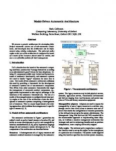
Language Definitions In order to support MDA, languages must be precisely defined, that is, they must have precisely defined syntax and semantic domains and a well-defined relationship between these two domains. These three essential components can be modelled using fairly simple UML concepts. A precise semantics is essential for defining complete and sound relationships between PIMs and PSMs and between all other MDA components. A precisely defined language consists of (1) a concrete syntax (the human-centric view of the language as it is typed into an editor, drawn on a screen or printed on a page); (2) an abstract syntax (the computer-centric representation of concrete syntax suitable for manipulation as data structures in a program); (3) semantic domain elements that define the denotation of syntactic elements; and (4) well-defined mappings that link concrete to abstract representations, and abstract representations to their meaning. We will use a simple language to express key features of language engineering technology * Field for MDA. The language is intended to support -name : String -type : String -fields the system analyst when capturing business * -state rules. A system definition consists of the following features: a name; a set of sub-events * System Event systems; a set of named input events -name : String -name : String * consisting of simple fields; a state consisting -subsystems * of a set of fields; and a collection of rules. * -rules Each rule has an antecedent that is a condition Rule expressed in terms of the fields on an input +fires() : Boolean event and a consequent that is a pair consisting of a collection of output events and a condition on the system state. The abstract syntax definition is given above (details on how rules are represented are omitted). A rule r has an operation ‘fires’, where r.fires(e,S,S’) is true when e is an event that triggers r, S is a set of fields defining the pre-state of the system and S’ is a set of fields defining the corresponding post-state. A system executes by selecting a rule whose antecedent is enabled by some input event. The input event is consumed and the corresponding output events are produced along with the required change in system state. The abstract syntax model given above is a meta-model; its instances are models in the sense that a model for Java has instances that are programs; the programs then have instances that are computations. A computation for a business system is a history of system states where state transitions occur due to system events. A state in a computation is a set of named values. A computation is a well-formed meaning for a business system when the events in the computation match up to the events in the system model and the names used in system states match the fields given in the system model. In addition, each transition in the computation must fire at least one of the rules in the system model. AbstractSyntax
Compositionality Compositionality of the MDA process is essential since the efficacy of the approach will depend on controlling the complexity of large numbers of models and their interrelationships. Compositionality within MDA can be achieved through the use of package specialization. A package is a container of model elements. If one package specializes another package then it includes all of the elements from the superpackage and adds new elements of its own. Where the names of corresponding model elements overlap (due to local definitions or multiple inheritance) the elements are merged. For example, suppose that we wish to decompose the definition of the business language abstract syntax into three aspects: the events E v e n t that can be received from the environment; the rules A s p e c t that control the reaction of the business system; and, the state of the business. This can be S ta te R u le s achieved by defining each aspect in a A s p e c t A s p e c t different package. packages are then combined using package specialisation as shown on the left. Merging rules ensure that the different A b s tra c t S y n ta x aspects are combined correctly to produce the required definition of abstract syntax. The package composition is shown on the left.
Patterns Patterns will arise in language definitions and MDA. For example, many languages exhibit standard properties such as containership and dynamic behaviour. The relationships between languages can also exhibit standard patterns in terms of structure or behaviour preservation. Patterns can be expressed using template packages. A template package is parametric with Container Contains Contained respect to model elements. A template is stamped out to produce a corresponding package in which all the formal parameters have been replaced with the * actual parameter values. For example, containership is a pattern that occurs repeatedly in the abstract syntax of the business language. A template is expressed as a package whose parameters are listed in a dashed box on the top right. In the body of the package the parameters are referenced within chevrons. The actual parameter values are supplied in a box attached to an arrow linking the resulting package with the template. The same template may be stamped out multiple times in which case each occurrence is identified by a different parameter box. The structural features of the semantic domain for the business language stamped out using the containership template is shown below. The term occurrence signifies that the corresponding elements are execution time entities domain.
C o n t a in s S y s te m O c c u rre n c e E v e n tO c c u r re n c e E v e n tO c c u r re n c e F ie ld O c c u r r e n c e S y s te m O c c u rre n c e S y s te m O c c u rre n c e S y s te m O c c u rr e n c e F ie ld O c c u r r e n c e
S e m a n t ic D o m a in S y s te m O c c u rre n c e
F ie ld O c c u r r e n c e
- n a m e : S t r in g - v a lu e : O b je c t
- n a m e : S t r in g
E v e n tO c c u rre n c e
- n a m e : S t r in g
Relations MDA relies heavily on relations and mappings. Relations should be non-intrusive (domain and range do not necessarily have to Nam e R e la tio n know about the relationships). Relations need D o m a in Range to be compositional and there are many standard relationship patterns. The template on the left can be used as the * root of many relation patterns. The relation < D o m a in R a n g e > P a i r - le f t - r ig h t is named and has a domain class and a range < D o m a in > class. The relation consists of a collection of pairs each containing an instance of the domain and an instance of the range. There is no restriction on the relation regarding which domain and range elements are paired. Standard relationship properties such as functional and one-to-one can be expressed as specializations of the basic relationship template. This leads to a powerful language for specifying relationships, see [7] for more details.
Semantic Mapping (System Meaning) In general a semantic mapping will involve both structural and non-structural constraints that determine legal pairings of syntax and semantics elements. We would like the semantic mapping to exhibit the following features: it should be simple, easily understood and use diagrammatic notation where possible; it should be able to reuse patterns where possible; it should be compositional and modular; where possible it should be amenable to machine processing since it can be used to S em antic D om ain generate test cases and even to S ystem M eaning animate a language definition S ystem R elation A bstract S yntax
S ystem O ccurrence
E ventM eaning E vent E ventO ccurrence
S em antic M apping
FieldM eaning Field FieldO ccurrence
We propose a novel technique called object theories that allows mappings (including semantic mappings) to be
expressed such that the criteria given above are achieved. The diagram on the left constructs a free semantic mapping in which no constraints limit the pairing of syntax and semantic elements; the constraints will be given as object theories as described in the following sections.
Object Theories OCL is used to express well-formedness constraints and to define the set of pairs associated with a relation. Experience in defining the UML 2.0 RFP submission [13] would suggest that the combination of templates and OCL to express such constraints is powerful, but can become complex in the sense that some of the structure of the constraints is lost in the OCL language. Object theories are a mechanism that allows the constraints to be structured and composed in layers. This section introduces object theories and subsequent sections discuss a new mechanism for expressing the theories and combining them. Examples are given with respect to the simple business language. An object theory is a collection of UML static semantics snapshots. A collaboration diagram or a sequence diagram can be viewed as the presentation of an object theory. Typically we define the structure of a domain by stamping out templates and combining the resulting packages using package specialization. This in itself defines an object theory; but typically one that expresses a free structure, i.e. there are no restrictions on the linkage between objects that are instances of the resulting classes. Such a freely constructed domain model is then specialized by combining new object theories that rule out certain object configurations. This process is incremental, modular and reversible. A method for MDA using object theories proceeds as follows: all the domains are defined independently using template technology; object theories can be used to define well-formedness rules on the freely constructed domains; the structure of semantic mappings are defined using templates; object theories are then used to complete the constraints over the freely constructed semantic mappings; the resulting language definition is can then be related to other language definitions (perhaps PIM to PSM languages) by template defining freely constructed relations and then mixing in constraints using object theories. Object theories are constructed by combining partial theories. This raises an issue regarding consistency: are there any models of the resulting theory? This is an important issue and must be checked, ideally using tool support.
Object Theory Presentations Object theories, as described above, are not particularly new since any UML diagram can be viewed as an object theory. However, UML notations provide only partial sup-
port for object theories and do not precisely define how such theories can be combined. We propose a new type of diagram and equivalently a textual language for UML object theory presentation. An object theory diagram (OTD) is based on object diagrams together with OCL constraints over the variables used to name objects. The differences are as follows: OTDs are expressed in packages and are amenable to package specialization and template definition; OTDs can be partitioned into subOTDs understood to be combined using disjunction; OTDs can be defined as axioms or rules where an OTD axiom is just an object diagram + OCL and a rule has a number of antecedent object diagrams, a consequent object diagram and an OCL side condition; OTDs allow links to be expressed as combination links or singleton links. A combination link leads to an object representing the set of values linked to the object where the link labels all have the same name. A singleton link is one of the possibly many links with a given label leading from an object. Groups of links are labelled to determine whether they are partial (there may be other links with the same label that are not shown on the diagram) or total (all the links with the given label are accounted for). A theory can also be expressed as a definition in a textual language. The language is more amenable to mechanical processing being easy to construct without sophisticated graphics based tools. A theory named T is expressed as a definition: theory T [ extends theories ] body end The body of the theory is a constraint on the valid theorems. A theory can be defined as an extension of an existing theory in which case all of the extended theorems are imported into the theory. The body of a theory is a disjunctive collection of rules. Each rule has an antecedent and a consequent (the degenerative case occurs where the antecedent is empty). The antecedent and consequent of rules are snapshots which are collections of object patterns. The textual language for object theories is more flexible than OTDs which can easily get cluttered. In addition, the textual language can easily be extended with new theory operators that might be difficult or clumsy to express on a diagram. In the rest of this paper we will use both notations. FieldMeaning The example on the left shows an OTD axiom defining the semantics :FieldField of fields. A field occurrence is a OccurrencePair valid meaning for a given field if the :FieldOccurrence names agree and the value of the :Field name = n occurrence satisfies the type declared satisfies(v,t) name = n value = v type = t for the field. When this theory is combined with the free definition of the relation FieldMeaning the legal instances of FieldFieldOccurrencePair are constrained so that the names agree and the type of the value is legal. The theory FieldMeaning gives a simple example of how theories can be used to construct relationships between models. In general a relationship can be defined as a class with associations to n (in the case or FieldMeaning n = 2) model elements. The theory defines when the relationship is well formed by placing constraints on the associated
elements. Complex relationships can be decomposed into combinations of simpler relationships. The textual representation of the theory is as follows (from now on to save space long class names will be abbreviated): theory FieldMeaning obj :FFOP left = obj :Field name = n; type = t end; right = obj :FO name = n; value = v end end such that satisfies(v,t) end
Just as patterns occur in static structure (for example containment), patterns occur in object theories. Package templates are used to express patterns in static structure; object theory templates are used to express patterns arising in theories. Object theory templates are illustrated in [14].
Refactoring and Refinement One of the key features of MDA is the ability to define relations between languages. These relations must hold between both the abstract syntax domains and the semantic domains of the languages. In order to be useful, the relations between languages must explicitly define the properties that they preserve between the languages. Relations may hold between instances of the same language. The refactoring relationship is one such relationship. Refactoring occurs when a software artifact (models or code) is changed to improve specific qualities while preserving the essential properties of a system. A refactored artifact represents an improvement in how a desired result (characterized by the essential properties) is accomplished. This section gives a very simple example of a refactoring with respect to the example business language. The business language supports sub-systems. The definition of execution for the language requires that sub-system steps are performed during a single super-system step. One possible refinement of a system is to decompose a single system into two sub-systems. If system A is refactored into A’ consisting of two sub-systems B and C then the events handled by A are also handled by A’, but instead of causing a state change in A, A’ delegates the event to either B or C. Therefore the events handled by both B and C are disjoint sub-sets of the events handled by both A and A’. The state of A’ is empty and the state of B and C are disjoint sub-sets of the state of A. Given a set of events E, a set of fields F and a set of rules R suppose that complete(E,F,R) holds when all rules in R handle only events in E and require only fields F to determine whether they are enabled and to determine the result of firing the rule. Suppose that given a set of rules R, a set of events E and the name of a sub-system n that delegate(R,E,n) holds when the rules in R all handle events in E and delegate the event to the sub-system n. A simple binary refactoring is expressed by the following theory named BinSplit. The theory defines a relationship called Split between a system (left) and its decomposition into two sub-systems (right):
theory BinSplit obj :Split left = obj :System fields = F1->union(F2); events = E1->union(E2); rules = R1->union(R2) end; right = obj :System events = E1->union(E2); rules = R1’->union(R2’); fields = Set{}; subSystems = Set{ obj :System name = n1; events = E1; rules = R1; fields = F1 end, obj :System name = n2; events = E2; rules = R2; fields = F2 end} end end such that complete(E1,F1,R1) and complete(E2,F2,R2) and delegate(R1’,E1,n1) and delegate(R2’,E2,n2) end
A theory of refactoring must also define how semantics are restructured and then show that the transformations preserve certain properties. Since out approach uses modelling techniques to express both the syntax and the semantics of a language, we can use the same techniques to express a theory about semantic refactoring and use the theory to check the appropriate properties. A systematic, automatable approach to model refactoring is possible when the transformations need to accomplish refactorings involving well-defined sets of source and target models, can be precisely characterized. An approach to UML model refactoring, based on the notion of UML (meta) Role Models has been developed [8]. A Role Model is a restriction of the UML meta-model, that is, a Role Model determines a sublanguage of the UML. One can view a Role Model as a characterization of models (precisely those models that can be expressed in the UML sublanguage). A particular type of Role Model that has been A particular type of Role Model that has been used to define refactorings is the Static Role Model (SRM). An SRM is a characterization of static UML models (e.g., Class Diagrams). In this approach, a characterization of a family of model refactorings consists of the following elements: A source model set: This set consists of source models for the refactorings. The set is characterized by Role Models; A target model set: This set consists of target models for the refactorings. The set is characterized by Role Models; A transformation set: This set consists of transformations that each accomplish the refactoring goal. A transformation specifies how a source model is transformed to a target model. In our work, transformations are expressed in terms of subtransformations a source model undergoes as it is transformed to a target model. An example of a pattern-based design refactoring is illustrated in [8].
Implementation A key feature of MDA are mappings from PIMs to PSMs. In general implementation involves several inter-language relationships. Object theories can be used to construct such relationships. This section gives a simple example of an implementation. Suppose that we have a model of a simple dynamic modelling language involving packages, classes, attributes and methods. A method has a collection of parameters, a body that is a simple action and a post-condition in terms of the attributes of the
containing class. The semantic domain of this language has definitions for objects and object steps. Each object step is labelled with the method call that caused it to occur. This language can be used to implement the business language by using object theories to construct the following relations: state fields become attributes; events become method signatures; rule conditions become the pre and post-conditions of the method that corresponds to the event that triggers the rule; rule actions become method bodies; systems and sub-systems become classes; sub-systems of systems are flattened. Space limitations prohibit a detailed description of the transformations. See [14] for more details.
Conclusion In this paper we identify requirements for an MDA approach to system development and outline a framework that consists of principles, techniques and mechanisms that support an MDA approach. The framework is intended to guide our work on developing an integrated set of processes, techniques, and mechanisms that cover all aspects of system development and that raises the abstraction level at which system engineers develop implementations above the code level. The approach to language engineering has been developed as part of a submission to the UML 2.0 revision initiative. Further details about package specialization can be found in [4], examples of the use of templates to construct a modelling language can be found in [3] and a complete definition of the UML core infrastructure can be found in the current submission to the OMG [13]. The initial ideas related to package specialization and templates are drawn from Catalysis [6]. Information about defining and combining aspects of systems can be found in [5]. This work is related to other research that addresses expressing constraints and relationships between models such as [9], [12] and [1]; and in particular with proposals for graphical constraints. The constraint diagrams of [10] and the graphical OCL diagrams of [2] are clearly related to this work. However, any technology that supports MDA must allow relationships between models to be performed in the sense that given a complete (or partial) description of one side of a binary relationship there should be an effective procedure that calculates the other side of the relationship. Our work is novel in that it aims to achieve this by restricting the form of theories that define the relationships in the same way that Horn Clauses restrict the form of logical formulas. We intend to develop the language of object theories and to define a complete semantics for the language (using the techniques defined in this paper). In addition, we intend to build a tool that can perform object theories and to use this to develop a theory of MDA based on definitions of model transformations such as refactoring and refinement.
References [1] Akehurst D. H. and Kent S. (2002) A Relational Approach to Defining Transformations in an Metamodel. UML 2002, Dresden [2] Buttoni P. et al. (2001) A Visualization of OCL Using Collaborations. In Gogolla and Kobryn eds. UML 2001 - Modeling Languages Concepts and Tools. Toronto, Canada 2001. [3] Clark A., Evans A., Kent S. (2002) Engineering Modelling Languages: A Precise Meta-Modelling Approach. Presented at the ETAPS FASE Conference, Grenoble France, 2002 [4] Clark A. Evans. A. Kent S. (2002) Package Extension with Renaming. To be presented at UML 2002, Dresden, Germany. [5] Clarke S., Walker R. J. (2001) Composition Patterns: An Approach to Designing Reusable Aspects, in Proceedings of ICSE'2001, May 2001. [6] D'Souza D., Wills A. C. (1998) Object Components and Frameworks with UML -The Catalysis Approach. Addison-Wesley. [7] D'Souza D. (2001) Model Driven Architecture and Integration. Available from http://www.catalysis.org/omg/. [8] France R., Kim D., and Song E. (2002) Patterns as Precise Characterizations of Designs. Technical Report 02-101, Computer Science Department, Colorado State University, January, 2002. [9] Gogolla M., Richters M (2002) Expressing UML Class Diagram Properties with OCL. In Clark A, Warmer J. (eds) Advances in Object Modeling with the OCL. Springer Verlag, LNCS 2263 [10] Kent S. (1997) Constraint Diagrams: Visualizing Invariants in Object-Oriented Models. In Proceedings of OOPSLA '97, 327 -- 341. [11] The OMG (2001) Executive Overview: Model Driven Architecture. Available from http://www.omg.org/mda/. [12] Richters M., Gogolla M. (2000) Validating UML Models and OCL Constraints. In Evans A., Kent S., Selic B. (eds) UML 2000 The Unified Modeling Language -- Advancing the Standard. Third International Conference. York, UK 2000. Proceedings volume 1939 LNCS, 265 -- 277, Springer-Verlag. [13] 2UP UML 2.0 (2002) Infrastructure Submission. Available from the OMG web site at: http://www.omg.org/techprocess/meetings/schedule/ UML_2.0_Infrastructure_RFP.html.
[14] Object Theories White Paper (Clarke, Evans, France). Available at: http://www.cs.colostate.edu/~france/theories.pdf.