observations of the social and situated organisation of human computer .... Macintosh is a trademark of Apple Computer Inc. and PowerPoint is a trademark of.
System Use and Social Organisation: Observations on Human-Computer Interaction in an Architectural Practice
Paul Luff and Christian Heath Technical Report EPC-1992-120
Published in: Technology in Working Order: Studies of Work, Interaction, and Technology, Graham Button (ed), Routledge, London, 1993, pp 184-210.
Copyright © Graham Button, Paul Luff and Christian Heath 1992. Rank Xerox Research Centre Cambridge Laboratory 61 Regent Street Cambridge CB2 1AB Tel:+44 1223 341500 Fax:+44 1223 341510
System use and social organisation: observations on human computer interaction in an architectural practice Paul Luff and Christian Heath
University of Surrey / Rank Xerox Cambridge EuroPARC
The ‘bricoleur’ is adept at performing a large number of diverse tasks; but, unlike the engineer, he does not subordinate each of them to the availability of raw materials and tools conceived for the purpose of the project. His universe of instruments is closed and the rules of his game are always to make do with ‘whatever is at hand’; that is to say with a set of tools and materials which is always finite and is also heterogeneous because what it contains bears no relation to the current project, or indeed to any particular project, but is the contingent result of all the occasions there have been to renew or enrich the stock of maintain it with the remains of previous constructions or destructions. (Lévi-Strauss p.17)
Introduction Despite its relative importance within the field of Human-Computer Interaction, there seems to be growing skepticism of the ability of cognitive science to enrich our understanding of the use of complex technologies. At the practical level, for example, it has been suggested that the designs and evaluation techniques used by actual designers of computer systems owe little to the models developed within cognitive science (Carroll 1990, Barnard 1991). Moreover, theoretically, cognitive science has been subject to wide ranging criticism concerning for example, its conceptualisation of
social action (Winograd and Flores 1986, Lave 1988, Coulter 1989), its approach to user modelling (Suchman 1987, Gilbert 1987) and its intentional models of language and discourse (MciIlvenny 1990, Frohlich and Luff 1990). In line with these criticisms, several researchers have argued that studies of should move away from plan based, goal orientated models of system use and begin to consider the social and cultural foundations of screen based actions and activities (Suchman 1987, Robinson 1990, Frohlich and Luff 1990, Norman and Thomas 1990). In the following chapter we attempt to make some preliminary observations of the social and situated organisation of human computer interaction. The observations demonstrate the ad hoc and improvisational properties of computer use and suggest that more conventional characterisations of the interaction between a human and computer tend to conceal, rather than illuminate, the practical reasoning and competences that ordinary users bring to bear in undertaking screen based actions and activities. Although the bulk of our observations are directed towards the individual use of the workstation, the chapter attempts to demonstrate how seemingly individual screen based activity is embedded in real time collaboration with colleagues undertaking related tasks within the organisation milieu. The materials upon which the observations are based consist of videorecordings of 'naturally occurring' computer use and collaboration in a provincial architectural practice in England. The architects are based in an open plan office and use a computer aided design (CAD) package to construct drawings on personal workstations. At various stages during the course of particular commission, the architects will be given the responsibility to undertake drawings of a particular section or details of the building. Despite this division of labour however, it is necessary for the architects to continually collaborate in order to produce a consistent set of drawings. Not withstanding the intrinsic sociological interest of the work of the architects, the materials at hand are also of relevance to current initiatives in research on human computer interaction. First, the CAD system used by the architects incorporates a direct manipulation interface and a direct metaphor. There has been a considerable amount of research into these ideas (Hutchins, Hollan and Norman 1986, Norman 1988, Ankrah et al. 1990), primarily because they are considered useful and good properties and yet it is unclear, precisely, what the character of these properties are. Second, analysis of the collaboration required to produce a set of drawings even when produced on individual machines may later inform the design of computer systems to support collaborative work (CSCW systems), and in particular those systems designed to support shared drawing between people in separate locations (e.g. Bly 1988, Minneman and Bly 1991, Ishii 1990).
Human-computer interaction in an architectural practice With their aim of modelling the knowledge of users of computer system, cognitive scientists concerned with human-computer interaction
frequently presuppose that different behaviours reflect differing levels of expertise. Thus, subjects for experiments are commonly divided into ‘experts’, ‘intermediates’ and ‘novices’, the category chosen based on the frequency of use of a particular application or computer system and familiarity with the task the user is being asked to perform (e.g. Mayes et al. 1988). Similarly, evaluations of computer systems are typically carried out using subjects with different ‘levels of expertise’ (e.g. Doane et al 1990). Recently, Young et al. (1990) have begun to explore more deeply the knowledge users have of a computer interface, analysing this knowledge in terms several classes; users having differing combinations of knowledge from these classes. They use the terms of ‘expert’, ‘intermediate’ and ‘novice’ to identify notional users having particular configurations of knowledge from the classes. In a previous study we undertook, individuals were asked to produce overhead projector slides using a specialised Macintosh application called P o w e r P o i n t 1 (Luff and Heath 1991). From recorded materials of naturalistic use of this system it was difficult to associate the behaviours proposed by Young et al. for their notional classes of users. Rather than characterising skill in terms of knowledge and expertise, it was more fruitful to examine the common practices that underlay the use of the system. As with many applications it is difficult to find ‘expert’ or ‘frequent’ users, defined in either of the ways mentioned above, of a package for producing overhead projector slides. Such a package is designed for ‘occasional’ users. However, there are other similar text and graphics packages that are used frequently; computer-aided design (CAD) packages, for example. For this and other other reasons we chose to study the use of computers in an architecture practice. The practice we studied is small to medium sized, employing about 15 architects, town planners and graphic designers. It is an unusual British practice in that it uses computers extensively throughout the process of designing a building including: showing clients what prospective buildings will look like and how they will fit within the local landscape; producing the working drawings for building contractors, and even drawing sketches of original designs. The setting is particularly suitable for our research because each architect has a Macintosh computer, the system we used in our earlier exercise and in other studies of humancomputer interaction (e.g. Mayes et al. 1988 and Young et al. 1990). The architects use a package called MiniCad2, each architect working on a different set of drawings. The materials collected are principally concerned with the principal project in which the practice was involved. This was to produce the working drawings for a large public building originally scheduled to take about ten months. The original designs had been produced by another architecture practice and the work involved producing drawings that were both detailed and consistent for the building 1 2
Macintosh is a trademark of Apple Computer Inc. and PowerPoint is a trademark of the Microsoft Corporation. A trademark of Graphsoft Inc.
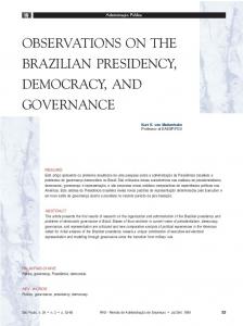
contractors to use. This project consisted of two parts: the demolition and redevelopment of portions of an old, existing building and the design of a completely new building linked to the old one. As well as producing plans, sections and elevations of these buildings3 the architects had to work on detailed drawings of complex parts of the design, these included the staircases and the large, high windows of the new building. Both the number of architects involved in the project and the number of drawings varied throughout the course of the project. During the period of data collection around six architects were working full-time on the building. The project was divided in terms of the drawings that had to be produced: one worked on the old building, one on the plans for the bottom six levels of the new building; one on the plans for the top five levels; one on the sections, one on the elevations and one on the staircases. Another architect was concerned with managing this and other of the practice’s projects and an eighth worked on drawings of the windows as well as other projects. The collected materials consist of fieldnotes and video-recordings of individual work, ‘interactions’ with the computer and collaborative work between architects. All the architects on this project used the MiniCad package. As a Macintosh application it shares many features with other applications for that system. Figure 1 shows the overall screen layout when MiniCad has been opened for the first time.
Figure 1: The MiniCad Screen
The main window is labelled ‘Untitled’ until the drawing has been named. MiniCad’s tools are provided on two palettes, initially on the left hand side of the screen. The top one contains drawing tools allowing 3
Plans cut through a building horizontally about 1.5m above floor height, sections cut through vertically, usually at places where there are significant changes to the shape of the building, and elevations show the sides of the building viewed from the outside and capturing all its possible faces.
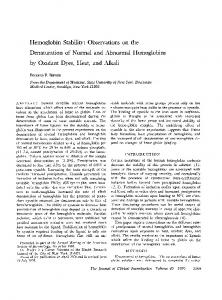
users to type text, draw rectangles, polygons, arcs and special, recurring symbols such as double doors and desks. The bottom palette is for a set of constraint tools that allow the user to constrain the placing of certain objects on the screen, for example, constraining one line to be perpendicular to another or ensuring that two objects fit precisely together. The data palette is initially available above the main window and provides users with the facilities for naming objects they have drawn and assigning textual information to those objects. Below the main window is a ‘data display bar’ that provides information about that status of the drawing at a particular time. Above the main window is a menu bar. Figure 2 shows the menu bar and the contents of the individual menus.
Figure 2: MiniCad Menus
In addition to the Apple menu available on all Macintosh applications, there are eleven MiniCad menus. The File and Edit menus have similar options to those in other Macintosh applications for opening, printing, saving and closing files and for simple editing operations. These menus also include options for smoothing, mirroring and reshaping objects. The Tool menu collects together several miscellaneous functions including joining objects together, combining several lines into a polygon, breaking up a polygon into several lines and changing surfaces for later threedimensional manipulation. MiniCad allows the user to create a drawing in layers. These act rather like tracing paper, except that the user not only has control over which layers of a drawing can be seen at any time, but also how each layer can be used, so certain layers can be invisible, greyed out, visible but unchangeable or visible and changeable. Options for manipulating layers are given in the menu labelled ‘==‘. The Text menu offers a range of ways of changing the style, font, size and layout of text. The Page menu allows the user to view the drawing in various ways. Another way of viewing a plan is to change it into some 3D representation, the Delta menu labelled ‘ ∆ ’, provides users with a multitude of possibilities for creating such a drawing. The Color menu provides ‘pens’ for drawing and shading objects on the screen in different
colours and the Fill menu offers a range of shadings (or hatchings) for objects. The Line Weighting menu, labelled ‘//’, gives a variety of styles of lines in differing thicknesses, differing dashing patterns and with differing arrowheads. Finally, MiniCad also provides for the user to associate spreadsheets (or ‘worksheets’) with drawings. The rightmost menu, the command menu, provides options for manipulating these. From the facilities offered on the menus it can be seen that MiniCad is a complex application containing a wide range of facilities. The architects appear to use most of these, including the spreadsheet for managing the progress of projects. The major component of the package they do not use is that for converting plans into 3D. Although one of the architects does create 3D drawings of the building and others they are working on, this is done using another Macintosh application. Before considering the architects interaction with the computer in more detail, it is worth mentioning the three principal mechanisms that MiniCad provides for moving around a drawing. These are zooming, panning and moving between layers. Zooming in and out of an particular portion of a drawing are performed by selecting the Zoom In and Zoom Out tools in the drawing palette (on the second row). To zoom in on a portion of the drawing, the Zoom In tool is selected with the mouse, the user specifies the area to zoom in to by shaping a dashed box, called a ‘Marquee’ over the appropriate area with the cursor and then releasing the mouse. Moving around a drawing that is too big to fit on the screen is possible by panning around the drawing either by using the panning tool on the drawing palette or by pressing the appropriate arrow key on the keyboard. The user can move between the layers of a building in three ways: using the Layer menu; selecting the ‘Lyr’ section of the data display bar at the bottom of the screen or pressing the Command key and either the up or down arrow at the same time.
The practice using menus Previous analysis of individuals producing overhead projector slides revealed that in the course of this activity the nature of their use of menus changed from moment to moment (Luff and Heath 1991) Although designing a building using a CAD package is quite a different activity, the architects uses of menus are similar in many ways. For example, in the following instance the architect is working on an elevation of the old building4. 4
Faced with the complexity of the conduct revealed in the video-recordings of screen-based activity, it was necessary to develop a transcription system to be used alongside the recordings. The titles of menus, for example ‘Fill’, are used to show when they are selected by the user and highlighted on the screen. They are written down the page whereas when the user highlights particular menu items they are written to the right of the menu title. Colons are used to capture the timing of the activity, each colon for one tenth of a second. Pauses between activities are given in seconds in parenthesis. Up and down arrows represent when the user presses or depresses the mouse button; the bracketed heading such as ‘[Untitled]’ is for the
(2) 4B MV 5124 1 2 3 4 5 6 7 8
↓ Fill::::::::::::::::::::::::::::::::::: Color::: Fill Foreground:::: (0.5) Color (Fill Foreground) (Fill Background) (Pen Foreground) (Pen Background) Use Layer Colors::::↑ (5.7) ↓ File::: New (Open) ↑ (2.3) ‘❀s’
He opens the Fill menu, holds it down for over 3 seconds (line 1), then goes down the adjacent Color menu (line 2), back up to the title bar, and then down again, selecting ‘Use Layer Colors’ (lines 3 - 4). After five seconds he briefly peeps at the File menu (line 6) before typing the command key and the ‘s’ key together (line 8)5 . It could be possible to characterise the first use of the menus (lines 1 - 4) as a ‘search’ for a particular item (i.e. ‘Use Layer Colors’) or as steps towards a solving a problem related to filling and colouring the drawing. Similarly, the second use (line 6) could be viewed as a search for the appropriate key command for saving a file displayed on the File menu. Although neither of these are behaviours that would be associated with ‘expert’ or ‘frequent’ users in the conventional menu literature, they could be seen to support the findings of Mayes et al. (1988). Mayes et al. found that ‘frequent users’ had difficulty in recalling even the ‘gross details’ of an interface. Thus, they propose, experts may have better 'semantic' knowledge of, for example, the existence of functions and therefore may not need to remember the 'lexical' knowledge of the names of particular functions. Good interface designs, like the Macintosh they were experimenting with, are those of which users do not need to remember the details. This argument ties in with other recent work in cognitive science which has begun to explore the relationship between ‘knowledge in the head’ and ‘knowledge in the world’ (Norman 1988). Utilising this distinction Young et al. (1990) have begun to develop a cognitive model of this relationship in terms of classes of knowledge that different users have when using an interface. Although being significantly more complex than those models that view actions as steps in a task or towards a goal, this work still concentrates on modelling the ‘knowledge in the head’ of an individual user. By being concerned with the ‘interaction’ between the internal knowledge of the user and the
5
region of the screen over which the mouse button was clicked. Users’ 'self talk' is shown in double quotes and follows the orthography of Jefferson (1972). A fuller description of the transcription system is given in Luff and Heath (1990) As with many other applications for the Macintosh, MiniCad offers users, what are called, ‘accelerators’ as quick alternatives to selecting items from menus. These are performed by typing combinations of keys simultaneously (called ‘chording’). In (5), the user types the command key labelled ‘❀’ and the ‘s’ key together. This performs the same operation as selecting ‘Save’ from the File menu. These chords are often displayed on the menu to the right of the appropriate item.
external knowledge in the artifact, Young et al. suggest that their model explores ‘situated’ action. This conception of situated action is significantly different to that in the social sciences, characterising the user’s activity in such a way ignores crucial aspects of the nature of the activity. In the following instance, the architect is working on a particular box on a plan. (3) 6B MV 4302 1 2 3
↓ //:::: ((Line thickness 1))::: ((Line thickness 2))::::: Fill:::::: Color::::::::::::: Put Down Color::: Use B&W Color: ↑
Once again, this activity does not appear to be that conventionally associated with experts using menus. It is also difficult to view it as a search for a solution to a particular problem, the line menu offering quite different possibilities for action to the Fill and Color menus. Instead, the nature of the activity of the user when engaged with the menus appears to develop in the course of using them. Although appearing to go to select a particular line width the nature of the user’s activity transforms as he is using the menus. A cognitive model of the type proposed by Young et al. (1990) would presumably account for this in terms of an interaction between the task the user is carrying out, the knowledge the user has of the system and what the system displays to the user. Yet such transformations of activity recur in the data, both in the materials collected in the architects practice and in that of PowerPoint users (Luff and Heath 1991). They do not appear to be associated with the user’s familiarity with the application or system. Characterising such activity as an interaction between knowledge in the head of the user and knowledge on the menus, focuses analysis on developing some mechanism or causal connection linking the two together and ignores the innovatory, improvisatory and, almost, ambivalent nature of the activity. Furthermore, by concentrating on individuals carrying out pre-designed tasks on systems, mainly in experimental settings, studies operate with a relatively constrained conception of screen based activity. In the following sections a broader view of situated action will be taken. By analysing naturalistic materials from real-world settings we will begin to explore aspects of the social organisation of human-computer interaction.
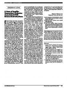
Directly manipulating plans Much of the architects day to day activity is involved in making detailed changes to the working drawings of the building. These changes are made using the CAD package. It is worth examining in detail an instance of this screen-based activity. In the following fragment an architect is making changes to a staircase in a drainage tunnel that leads away from underneath the building. Figure 3 is a sketch of the plan of the staircase.
(4) 7B MV 4284 Fragment I 1 2 3 4 5 6 7 8 9 10 11 12 13 14 15
Figure 3: The Tunnel Staircase (line 1, fragment 4)
1 2 3 4 5 6 7 8 9
↓ >Marquee:::::::::::::::::::::::>↑ (0.8) ‘❀c’ (1.4) ‘(❀↓ ❀↓ ❀↓ ❀↓)’ (1.5) ‘(❀↓)’ (1.9) ‘❀v’
The user has just been moving around the plan, both panning across it and selecting various layers of the drawing. He shapes a box (called a Marquee) over the region of a staircase (line 1), this marks the objects contained within the box as ‘selected’. He then types the command and ‘c’ keys simultaneously (line 3). He moves down five layers (lines 5 - 7) by holding down the command key and pressing the down arrow key. He then types the command and ‘v’ keys simultaneously (line 9). Together the actions in line 1 to 9 are commonly characterised as a ‘cut and paste’, or more accurately, a ‘copy and paste’. The architect copies a portion of staircase from one layer and pastes it onto another (see Figure 4). The architect goes on to manipulate the amended plan (4) 7B MV 4284 Fragment II 1 2 3 4 5 6 7 8 9 10 1112 13 14 15
Figure 4: The Tunnel Staircase (after line 9, fragment 4)
10 11 12 13 14 15 16 17 18 19 20 21 22
(7.2) ‘❀j’ (3.0) ↓ >Marquee:::::::::::::>↑ (0.3) ↓↑ (0.2) ↓ ((left point of arrow)) ↑ (1.6) ↓ ((right point of arrow)) ↑ (1.5) ↓ >((arrow))::::::::> ↑ (4.1)
He types ‘command-j’ (line 11), this ‘joins’ the new portion of staircase to the old. After marking out an area of the staircase that contains all the numbers of the individual stairs (line 13), the architect clicks in the area above the staircase (line 15). He then selects each end of the arrow and then moves it upwards and rightwards (lines 17 - 21). After positioning a construction line using the ‘+’ drawing tool and removing an indent in the wall below the staircase, the architect moves first the vertical wall to the end of the staircase (line 29) and then extends the horizontal wall (line 31). Figure 5 is a sketch of the plan at this point.
(4) 7B MV 4284 Fragment III ((moves construction line and indent in wall)) 28 (3.3) 29 ↓ >[Right Wall]::::::::::::::::::::::::::::::::>↑ 30 (2.3) 31 ↓ >[Top Wall]:::::::>↑
1 2 3 4 5 6 7 8 9 10 11 12 13 14 15
Figure 5: The Tunnel Staircase (after line 31, fragment 4)
The user removes all the numbers on the stairs and a portion of stairs at the left end of the staircase and then selects the right and left hand sides of the arrow (line 35 and 37). After appearing to group the ends of the arrow together (by the ‘command-g’ combination, line 39) he moves it into a new position on the stairs (line 41). (4) 7B MV 4284 Fragment IV ((removes numbers and stairs)) 35 36 37 38 39 40 41
↓ ((right point of arrow)) ↑ (1.5) ↓ ((left point of arrow)) ↑ (1.4) ‘(❀g)’ (2.9) ↓ >((arrow))::::::::::::::::::::::::::::::::::::::::::::::::::::> ↑
This fragment is extracted from an extended flow of activity. It is possible, post hoc, to view these actions as steps towards a goal that the architect had before commencing it or as part of sub-tasks that make up some overall task he had to accomplish. In order to extend the staircase, the user first has to copy the extended portion, consisting of a new flight of stairs from somewhere else, add this to the end of the staircase, then move the existing walls to surround this new portion and finally adjust the new staircase, removing any extraneous stairs at the bottom of the flight and changing the numbers that label each stair. Making fine alterations could then be characterised as local adjustments necessary to accomplish an overall goal. It could be expected that a mundane activity such as extending a staircase would, for an architect, be a routine, general procedure that, with minor alterations, could be instantiated for particular cases at hand. Yet, in the fragment above, and throughout the corpus of data, it is hard to discover such a procedure. Although it is possible to construct a post hoc ‘plan’ for an architect’s manipulation of a drawing, even for other manipulations of staircases, there appears to be no generality to these ‘plans’. Rather, the architect’s activity appears to be locally managed. When the new portion of staircase is pasted onto the old there are a range of actions to perform and a range of possible ways of performing them including: moving the walls and stairs; renumbering the stairs; and grouping, ungrouping and constraining the movement of the various, objects displayed on the screen. As the architect manipulates the plan
there remains a range of further and different possibilities for action. As with the use of menus mentioned earlier, the nature of the screen-based activity that the user engages in is continually changing throughout the articulation of that activity. The selection of the numbers of the stairs using a marquee (line 13) and then the subsequent click of the mouse button that deselects them (line 15) could be seen as the commencement of a new course of activity, such as moving or deleting those numbers, that is immediately aborted. Making a selection also brings into view a set of objects that can be manipulated. This alters the range of relevant next activities for the architect, the click away removes the marking, making another action, like selecting the left end of the arrow, possible (line 17). Rather than the activity being divided into segments, each concerned with a separate sub-task, an action is linked to the prior action and makes possible a range of next actions. Although architects utilise systematic procedures, or packages of actions, for getting their work done, they cannot be said to ‘follow’ these procedures. Rather, the architects orient to these procedures, innovatively using them to accomplish a task at hand. Hutchins, Hollan and Norman (1986) explain the properties of direct manipulation interfaces, such as MiniCad, in terms of the mappings between an individual’s goals and the physical tasks required to operate a system. They suggest that there are two aspects to the notion of directness of an interface: distance and engagement. Distance accounting for the translation necessary from goals into physical tasks. Engagement accounting for the ‘qualitative feeling’ of manipulating the objects of interest. Direct manipulation interfaces make the distance shorter by, for example, avoiding the semantic translation necessary to construct typewritten commands and increase engagement by employing visual metaphors of objects related to the user’s task on the screen. Other researchers have attempted to further clarify aspects of direct manipulation by, for example, exploring the differing rôles of direct metaphor and direct manipulation (Ankrah et al. 1990), and characterising the properties of screen objects in terms of their affordances (Gaver 1991). Though direct manipulation interfaces such as desktop environments, spreadsheets and CAD packages appear to be successful, being easy to use and learn, it has been difficult to explain this usability in terms of a cognitive model. This may be because such work tries to explain a direct activity in terms of intermediate and unseen processes. The recordings of architects reveal them engaged in using the tools of MiniCad and directly manipulating the objects that they have created, and yet it is hard to draw mappings between the corresponding ‘real world’ tools, actions and objects and those they use on the screen. In (4) the architect is directly manipulating plans on the screens using tools for moving and copying boxes and lines, positioning construction lines, constraining angles and joining objects together. In terms of metaphors with the ‘real world’ tools of pen, eraser, ruler, set square and tracing paper the MiniCad interface appears to be rather indirect. Also, it is difficult to imagine how a particular box on the screen ‘affords’ being moved. Yet, the user appears to do these activities quite unproblematically. It may be useful to explore the architects’ practices of using these screen-based tools.
Obviously, the positioning and sizing of objects is a crucial aspect of the work of the architects. Not only are they working on drawings to be used by building contractors that need to be accurate to about 5mm, but also the placement of objects must fit precisely across layers in a drawing and across separate drawings. In (4) the architect organises his activity so the location to which objects are to be moved are specified before he moves the object. The join command (line 11) does not just connect together two disconnected objects, it makes one object of two distinct objects. In the case of walls, the join command removes intermediary lines between two connected walls. So, the architect’s ‘paste’ of the new portion of staircase (line 9) is carefully designed for subsequent actions. The architect still has to make adjustments to the positioning of objects on the drawing, especially to related ones, but his manipulation of those objects could be better characterised as slotting them into a particular position rather than sliding or pushing them around the drawing. It is not the tools and the objects on the screen that are essential to the way the architect orients to his activity, but it is also the space on the screen. In (4), the user moves the arrow on the staircase up and to the left (line 21). This position is nicely out of the way of the staircase, which the user goes on to manipulate, and also is vertically above the new location of the staircase. In the following instance the user is redrawing a plan of a toilet. (Figure 6 is a sketch of the plan before he has altered anything.) (5) 6B 5249 ↓ >((number)):::::::::::> ↑ (.) ‘return’ (5.2) ↓ >[Wall]::::::::::::::> ↑ (2.1) ↓ >[Wall]: ::::::::::::::::::::::::::::>↑ I: “um” (3.5)
1 2 3 4 5 6 7
270
Figure 6: Toilet (line 1, fragment 5)
8 9
After moving a number on the drawing (line 1), he deselects the number (line 3) then moves the left vertical wall to the right (line 5). (Figure 7 is a sketch of the plan at this point.)
270
Figure 7: Toilet (line 9, fragment 5)
The architect then moves another wall, originally in the same position as the wall he just moved, to the right hand side of the drawing (line 7). He then goes on to work in the space he has now left to the right of the urinals. As in (4) the walls are moved into a space clear but related to the area in which the architect is to work. Though in this case, one, and probably both, of these walls are no longer required for the plan. It is as if the walls, whose size and shape are still consistent with the rest of the drawing, are being preserved as a resource for further work. Such preservation of objects recurs throughout the corpus of data. There are also related instances where a copy of an object is moved into an area of free space and manipulated there. This manipulation could be characterised as a side activity; working out the precise shape of the object or trying out operations on it. The MiniCad package in particular, and the Macintosh system in general, facilitates the preservation of objects and the production of such side activities. So far we have considered solely the uses of local spaces, in the next section we will begin to consider wider aspects of direct manipulation in a CAD package.
Navigating around design As mentioned earlier, MiniCad provides three ways of moving around a drawing: panning across a drawing; zooming into and out of an area of a drawing; and moving between layers of the drawing. In the following instance the architect uses all three (shown schematically in figure 8).
(6) 4B 5417 7 ‘(❀4)’ 8 (18.3)
1 ((Pan ↑)) 2 (3.3)
9 10 11 12
↓ [Zoom Out] ↑ (0.3) ↓>Marquee:::::::>↑ (11.5)
3 ((Pan ↑)) 4 (3.3)
13 ↓ >[Window 14 Bar]::::::::::::::::::::> ↑ 15 (3.1) 16 ↓ [Bottom Window] ↑ 17 (2.5)
5 ((Pan ← )) 6 (2.5)
18 19 20 21 22 23 24
↓ [Zoom Out] ↑ (10.8) ↓ ∆::::::: Page:: (Text) ==::: Layer::::: ↑ ((selects items from dialogue window))
After working on the title in the bottom right hand corner of a set of elevations, the architect shuffles the drawing up twice by moving the cursor over the edge of the drawing (lines 1-3) and then across to the left (line 5). He types ‘command-4’ (line 7), fitting the entire drawing onto the screen. He then zooms out further using the ‘Zoom Out’ tool on the Drawing Tools palette and marks the area on the screen where he wants the less detailed drawing to go (lines 9 - 11). By selecting the top window bar of the window and dragging it down to the bottom of the screen he effectively moves the current set of elevations out of view and reveals another elevation (line 13). He clicks on this elevation (line 16), zooms out of this elevation (line 18), goes to the menus to select the layers of the drawings to display (lines 20 - 24) and he then goes on to alter the title block of this drawing. The architect not only moves from one drawing to another in three different ways, he accomplishes this by moving the mouse, using an accelerator, the menus and the ‘Zoom Out’ Tool. Just as in previous instances it is possible to consider this movement as a path from one title block to another; zooming out of the first plan, jumping across to the other drawing and then zooming in on that. But once again this ignores the development of the activity from moment to moment. In the following instance the user has just finished altering some walls at the right hand end of the service tunnel (shown schematically in Figure 9).
7) 7B MV 4470 1 2
'←’ (0.3)
3 4 5 6 7 8
'←’ (0.4) '←’ (0.5) '←’ (1.2)
10 11
(2.5) ‘↓’
12 13
(3.3) ‘↓’
14 15 16
(8.5) ‘↓’ (5.3)
17 18
↓ ==: Set Layer::::: Layers:::: ↑ (1.3)
19 20
((selects layers scrolling menus in the dialogue box))
21 22 23 24
↓ [OK] ↑ (0.7) ‘↓’ (12.0)
25 26
((Pans diagonally down and to the right))::::::::::::::::::::
Figure 9: Moving down the service tunnel
He pans left across the top of the tunnel six times (lines 1 - 9), then down three times (lines 11 - 15) by pressing the appropriate arrow keys. He
adds some layers to the drawing (lines 17 - 20), pans down again (line 23) then pans diagonally down to the right (line 25 - 26). The service tunnel is a bent ‘T-shape’ and enters the main building at its base. The architect pans across and down the plan following the service tunnel into the building. He also paces his activity with the system’s redrawing of the plan. It is possible to press keystrokes in quick succession, avoiding redrawing intermediate plans along the way. By slowing down the frequency of pressing of the arrow keys as he nears the centre of the service tunnel the architect is able to monitor the system redrawing the plan. Progression down the tunnel is slower and only after he passes the crook in the tunnel (line 15) does he add layers to the drawing and then proceed into the female staffroom in the new building. There are other ways in which the user could move between the staircase at the right end of the tunnel and the female staffroom; for example, zooming out to a plan of the whole drawing and then zooming into the relevant area. Yet, this activity rests on the architect’s skill of manipulating this particular plan and the system in general. MiniCad takes longer to draw the entire ‘level 0’ plan than to draw many plans of details. It also takes longer to draw such details if it has to draw several layers each time. Thus, the activity in (7) is organised and shaped by a range of contingencies including the architect’s pacing of his own actions with the system’s operations, the projected speed of the system, and the very shape and position of the tunnel on which the architect is working. This is a different form of direct manipulation to that normally considered in the literature on . ‘Direct navigation’ of this sort is facilitated by the contingent manipulation of objects. Navigation around the plan can also be seen as contingent on aspects of architectural practice in general. The building the architects are working on has certain consistencies and symmetries. The architects can make use of these in their drawings, for instance, copying portions of a plan from one area to another. It also means that work on one localised area of a plan has important implications for changes that need to be made to other areas. For example, changes to an internal staircase on one level will involve similar, but not identical, changes to other staircases on that level. In the materials there are numerous instances of movements back and forth between spatially distant areas of the plan. These movements rest on the architects’ skills of ‘interacting’ with the computer, drawing this particular plan and the everyday, architectural skills of drawing buildings.
Practices in support of multiple activities As in other practices, changes that the architects need to make to the drawings are ‘marked up’ on paper. There is one set of these mark-ups made on a recently plotted version of the drawings. The architects also keep paper versions of the drawings on which they are individually working. These paper versions have a range of advantages especially, as they are over a metre in length, it is possible to see more of the drawing than on a 30cm wide screen. These paper drawings also need to be
organised, plotted and marked. Similarly, the architects have other artifacts around their desk with which they have to work, including reference books, manuals and calculators. Thus, their interaction with the machine is embedded within a range of other activities. In the following instance, the architect selects a menu item to export a file into a different format (line 3). He then types the new file’s name into a field in a dialogue box (line 7). (8) 14B JVC 3500 2:20:18 Transcript I ↓ == Set Layer:::::::::::::::: Layers... Layer ↑ ↓ File:::::::::: Export::: (Item1) (Item2:) (Item3::) ↑ (2.3) >‘((file name)):::::> (0.8) ‘((new file name)):::::::::::::::::::::::’ (1.0) ↓ [OK] ↑
1 2 3 4 5 6 7 8 9
Prior to this activity the architect is marking up a paper plan. As he lifts his pen from the paper he looks toward the screen to his right. Just after his glance reaches the screen, he moves towards the workstation and reaches out for the mouse. He then selects the item from the menu. This brings up a dialogue box that has a default file name in it which he drags the mouse over (line 5). This allows him to replace the default name with a new one (line 7). After he selects the ‘OK’ button in the dialogue box he goes back to the drawing. The following figure maps out the architect’s visual conduct and some of his other activities6. (8) 14A JVC 3596 Transcript II
looks at screen (6.0)
looks at screen (0.5)
puts pen down
drags over text
moves to workstation (1.3)
seconds
6
0.5
1
1.5
2
3
4
5
6
7
7.5
A transcription notation for visual conduct is described in Goodwin (1981) and Heath (1986). For the purpose of presentation in this chapter, gaze movement is shown by a line above which is the name of the object the architect is glancing at (e.g. screen, desk or paper plan).
looks at keyboard (1.7) looks at screen (1.5)
picks up pen
types
moves to drawing
8
8.5
9.5
9
10
11
10.5
11.5
The architect’s use of the computer is embedded in the other activities in which he is engaged. On glancing at the screen he moves over to the system and then starts interacting with it. After selecting ‘OK’ he glances down from the screen and moves back to his drawing. Such tight interleaving of two activities is not always possible. Instead, as in the following fragment, the architect may have to monitor the screen while engaged in another activity. (9) 14A 3277
looks at screen (5.8)
looks at plan
looks at screen (3.9)
starts rolling up plans
seconds
0.5
1
2
3
4
5
5.5
looks at plan
8
9
10
11
11.5
6
6.5
looks at screen (4.4)
12
14
15
16
17
7
looks at plan (0.8)
17.5
18
desk (0.9) screen (3.2)
screen (0.7)
screen (1.6)
moves to screen
18.5
19
20
21
22
22.5
23
23.5
24
25
25.5
desk screen (2.8)
screen (1.5) plan (0.5)
puts rubber band on plan and moves back
26
26.5
27.5
28.5
29
29.5
screen (1.5)
30.5
31
31.5
32
screen (1.3) plan (0.5) plan barrel (1.5)
33
34
33.5
34.5
35
35.5
36
36.5
37
screen (1.0)
38
39.5
40
41
So in fragment (9), although engaged in an activity of folding up a plan the architect is continually glancing at the screen. In this instance, the architect was opening a file of a particular drawing. As the drawing the architects are working on are complex, saving, opening, closing and plotting operations can take the system a long time to perform. It is often the case that the architects engage in another activity that ties into the speed of operation of the machine. It should be noted that a plan of the entire building that fits on the screen is very dense. When opening the drawing it is difficult to see from the drawing when the operation has been completed. It appears that the architects look for other aspects of the interface, such as the title bar or the existence of a dialogue box to monitor when the system is ‘available’. Miyata and Norman (1986) consider some work in psychology that may support the understanding of multiple activities, such as research on memory, attention and the processing of tasks. In particular, they suggest a distinction between foregrounded, backgrounded and suspended activity. They go on to suggest the advantages and disadvantages of windows to support such activities. In the corpus of data we are considering there are
occasions when the architects use more than one window, such as in (9) above, to contain alternative drawings with which to work or to compare an elevation to a plan. More interestingly, the architects can innovatively use other devices and tools provided on the computer system to support activities that do not take place on the screen, and switch from one of these activities to another from moment to moment. In such a flow of activity, the architects manage for themselves the assignment of foregrounded and backgrounded activities and the movement between the two.
Shared Drawing Not only must a single drawing be internally consistent so that items such as staircases between the same floors have equal number of stairs, but also the different types of drawings (i.e. plans, sections, elevations and details) must be consistent with each other. As different architects are responsible for these drawings consistency demands collaboration. The architects also collaborate in other ways: they have to organise and order the work of the practice; they have to monitor the progress and collect together the work on the building and they have to solve particular problems with the design of the building. The individual's use of the computer is embedded within surrounding domain of activity in the office. The mark up sheets are one of the ways that changes to the plans are communicated to one another. They also draw small details on ‘Post-it’ stickers and pass these to one another, they keep a spreadsheet of the progress of all the drawings for the project and, from time to time, pass computer files to each other. In fact, a number of procedures have emerged in the practice to facilitate the communication of plans. The practice has a policy for naming computer files that relates the name to the type of drawing it contains, its scale and the architect who is responsible for it. When files are copied from one machine to another this name is changed to avoid problems having two different drawings with the same name. Each drawing is positioned on a grid that is common to all drawings. This makes it easier to position portions of drawings taken from other files. Also, the architects try to avoid redundancy in their plans (i.e. plans sharing common details) as this increases the possibility of inconsistencies. However, none of these procedures ensure consistency. Rather consistency is achieved by the ways in which the architects monitor each other's work. For example, in the following fragment the architect working on the details of the staircases (R) is looking at the mark-up sheets while the architect drawing the plans (P) sits to his right working on his computer. (10) 8A JVC 3094 Fragment I 1 2 3 4 5 6
R: are you su:re you're flipping the right one arou:nd ↓ Pe:te. (0.2) P: yeah (2.5) P: your flipping (0.5) look on level one (1.1)
7 8 9 10 11 12 13 14 15 16 17 18
R: you you just told me that you have flip>flipped that one arou:nd (0.6) P: Yeah (0.3) I () R: it must be that one () what P: I’ve only just made these corrections now (0.9) these red marks (0.5) R: why do>does the red marks (.) go in different directions then the black? (0.8) P: no you want the red (0.4) this is correct R: (there ) (1.9) P: and this one I’m changing (0.2) you see this one goes up the other way ↑
About 1.4 seconds after he answer’s R’s question, T turns towards the plans and they start to discuss the ‘mark ups’ on the plans. Because of large scale changes to the overall design of the building a room has been moved onto a new split level towards the top of the building. The staircase to this room cannot just be extended up from an existing level. For access to the new room to be convenient the staircase has to go in the opposite direction. Turning (or flipping) the staircase around at the top level requires turning all the other stairs at lower levels. It is the mark ups relating to this change that the architects are discussing, in particular, the differing statuses of mark ups made in black and red ink. A little later the architects are discussing the details of the staircases. (10) 8A JVC 3094 Fragment 2 1 2 3 4 5 6 7 8 9 10 11 12 13 14 15 16 17 18 19
P: you see (0.3) um: (0.6) P: there this is the outside level (1.0) R: umm ↓ (1.3) P: and it can start (0.7) P: part of the drawing we’re on now (2.3) P: righ(t) yeah (1.4) P: youve done a section through (.2) this guy here right ? (0.6) R: yep (.) P: thats the stair of the section I had ↓(0.3) too: give myself () and he has set back these () and he has to start back here (0.4) and go up ↑
The talk in fragment 10 is accompanied by a considerable amount of visual conduct and gestures by the participants, particularly as they orient themselves to plans on the screen and on the paper. P begins to turn to his screen as he says “um:” (line 1) and on uttering “there” (line 3) he
points to a place on the bottom of a section on the screen, sketched in figure 10.
(line 4)
"there" (line 3)
Figure 10: Staircase section (fragment 10)
P’s pointing does not secure R’s gaze towards the screen. Only as P utters “side” of “outside level” does R gaze up to the screen. About 0.5 seconds after his utterance, P moves his finger along the bottom of the section on the screen. Both P’s utterance and his movement secure a response from R (line 5), but R remains oriented towards the plans on the desk. P then presses a key-chord zooming out of the section as he says “of the” in “part of the drawing” (line 9). R then begins to orient himself towards P’s screen and moves behind P as P is saying “youve done a section through” (line 13). Then P points back to the plans (on “this guy here right ?” - line 13). R gazes back at the plans and says “yep” (line 15). Meanwhile P gazes back at the screen and when he says “too:”, R also looks at the screen (line 17). Although this is only a brief outline of the vocal, visual and screenbased conduct in (10), it reveals a sequential relationship between these activities. P’s talk, gaze and body movement secure R’s alignment first to the screen, then to the paper plans and then back to the screen. P’s own activity is also tied to his . His key-command results in the system displaying a complete view of his drawing, consisting of many tiny sections displayed on the screen. P says “right yeah” just after this appears on the screen (line 11). As he says “had” in “thats the stair of the section I had” (line 17) he zooms into one of the sections which appears while he is saying “too:”. The gap and the extension of “too:” appear to draw R’s gaze to the screen. Particular visual alignments can be engendered through perturbations in talk; a restart, pause, extension or shift of gaze aligning another to a particular object (Goodwin 1981, Heath 1986). Here it appears that visual conduct and talk are also tied to the activity on the system. The irregularities or perturbations in the talk and the shifts of gaze and body movement being tied to the irregular pacing of the system’s operations and the variability of the contents of the screen. Although the system in fragment (10) is being used by a single individual, the zoom out and the zoom in, from one section to another, is thoroughly embedded within the interaction between the two architects. It is unclear how a cognitive model could account for this activity.
In this fragment, P uses both the screen and paper based drawings as a resource in his interaction with R. Various developments in CSCW have aimed to provide shared drawing tools for users, allowing them to collaborate over distances on the same drawing (Bly 1988, Ishii 1990, Minneman and Bly 1991). Analysis of video materials can point to some essential requirements for such systems to be useful in architectural settings concerning the visibility, size and orientation of displays. For example, it would appear necessary for the displays to be large and flat on the desk (or only slightly tilted). It would also be useful if they could interact with their plans in much the same way they interact with the present paper documents. Experiments with such ‘desktop’ interfaces where both images of electronic documents are projected onto the desk and paper documents are scanned through cameras are already currently underway at EuroPARC (Wellner 1991, Newman and Wellner forthcoming). Video analysis can also reveal some of the practices with which architects orient to the same object on the screen or on paper, practices that may not supported solely by providing multiple pointers on the screen. Some of the difficulties faced by designers of distributed drawing systems are just those that are concerned with how to embed the use of such devices within the talk and visual conduct of the users. Recent developments with video images and audio connections appear to be a way of addressing this issue (Tang and Minneman 1991).
Summary The work of architects not only depends on the work of others in the office, but also on a range of other individuals in different organisations. These include structural engineers, drainage engineers, building contractors, fire officers and the clients. In fact, all the instances of considered above can be directly related to the changing ‘requirements’ of outside organisations: the tunnel staircase had to be extended because of instructions to deepen the tunnel by the drainage engineer (fragment 4); the staircases had to be turned around because of the requirement for a new room from the client (fragment 10); and one of the justifications for drawing details of the toilets in old building is to give the drainage engineer something to work with so that he can design a drainage system (fragment 5). Recently, Hutchins (1985) has proposed a distributed model of cognition which attempts to take into account the differing goals of individuals in various technological environments (e.g. on the bridge of an aircraft carrier and in the cockpit of a plane, Hutchins 1990, Hutchins and Klause 1990). He proposes that particular artifacts, such as maps, charts and dials mediate between individuals with differing tasks, goals, knowledge and expertise. Presumably, the architects’ drawings are such mediating artifacts between the architects and between the architects and other individuals. Even this relatively radical reconceptualisation of the relationship between the individual, his or her activity and the computer system, does not appear to capture the situated and socially organised character of cooperative work revealed in the instances above.
In this chapter we have attempted to describe aspects of the humancomputer interaction in a real world, organisational setting. Even a cursory glance of the ordinary use of such systems within ordinary work tasks, as we have undertaken here, begins to reveal characteristics of computer use which cannot be incorporated comfortably into more conventional descriptions of the interaction between human and computer. For example, attempts to conceptually and empirically distinguish the internal and external knowledge of users unfortunately neglects the innovative and improvisational character of systems' use, and the ordinary competences upon which individuals rely in undertaking screen based activities in 'practical situations of choice'. Perhaps part of the difficulty in utilising more conventional cognitive models to characterise real world computer use, derives from their concern with conceptualising the knowledge a user has 'of' a system, rather than 'how' knowledge is used within the situated accomplishment of a range of social actions and activities. Users, and in this particular the case, architects, bring a range of resources to bear in producing and rendering intelligible screen based actions and activities, and more detailed analysis of the procedures, practices and reasoning involved in the accomplishment of technologically informed architectural work might well provide a more satisfactory characterisation of certain aspects of human-computer interaction. However, the naturalistic analysis of individual screen based activity does raise important methodological problems and it is not at all clear that at the present time the work discussed here, or related studies, have been able to provide satisfactory solution to those difficulties. Despite these difficulties, and placing to one side the various programmatic reasons for undertaking naturalistic studies of computer use, it would seem that preliminary observations of the use of complex by individuals in real world situations raises significant questions for some of the more important assumptions and conceptualisations which underlie a range of current work on humancomputer interaction.
Acknowledgements We should like to thank Marina Jirotka, Graham Button and colleagues at Rank Xerox Cambridge EuroPARC for their discussions and comments on an earlier draft of the chapter. Part of the research reported here was undertaken under the auspices of a Joint Cognitive Science Initiative (ESRC/MRC/SERC) Research Grant concerned with the Social Organisation of Human Computer Interaction.
References Ankrah, A., Frohlich, D. M. and Gilbert, G. N. (1990) ‘Two ways to fill a bath, with and without knowling it’, in Proceedings of Interact ‘90 - Third IFIP Conference on Human-Computer Interaction, Cambridge, August, 73-78. Barnard, P. (1991) ‘Bridging Between Basic Theories and the Artifacts of Human-computer Interaction’, in J. M. Carroll (ed.) Designing Interaction: Psychology at the HumanComputer Interface, Cambridge: Cambridge University Press.
Bly , S. A. (1988) ‘A Use of Drawing Surfaces in Different Collaborative Settings’ in Proceedings of CSCW ‘88, September, Portland, Oregon, 250-256. Button, G. (1990) ‘Going up a Blind Alley: conflating Conversation Analysis and Computational Modelling. in P. Luff, G. N. Gilbert and D. M. Frohlich (eds.) Computers and Conversation, London and New York: Academic Press, 67-90. Carroll, J. M. (1990) ‘Infinite Detail and Emulation in an Ontologically Minimized HCI’, in Proceedings of CHI ‘90, Seattle, April, 321-327. Doane, S. M., Pellegrino, J. W. and Klatzy, R. L. (1990) ‘Expertise in a Computer Operating System: Conceptualization and Performance’, Human-Computer Interaction, 5: 26730. Frohlich, D. M. and Luff P. (1990) ‘Applying the Technology of Conversation to the Technology for Conversation’, in P. Luff, G. N. Gilbert and D. M. Frohlich (eds.) Computers and Conversation, London and New York: Academic Press, 189-222. Gaver, W. W. (1991) ‘Technology Affordances’, in , in Proceedings of CHI’ 91, April-May, New Orleans, 79-84. Gilbert, G. N. (1987) ‘Cognitive and social models of the user, in H. J. Bullinger and B. Shackel (eds.) Human-computer interaction – Interact '87, Proceedings of the Second IFIP conference, September, Stuttgart, Amsterdam: North Holland, 165-172. Goodwin, C. (1981) Conversational Organization: Interaction Between Speakers and Hearers, London and New York: Academic Press. Heath, C. (1986) Body movement and speech in medical interaction, Cambridge: Cambridge University Press. Hutchins, E. (1985) ‘The Social Organisation of Distributed Cognition’, unpublished manuscript, University of California, San Diego. Hutchins, E. L. (1990) ‘The Technology of Team Navigation’, in J. Gallagher, R.E. Kraut, and C. Egido (eds.) Intellectual Teamwork: The Social and Technological Foundations of Cooperative Work Hillsdale, NJ: Laurence Erlbaum Associates, 191-221. Hutchins, E. L., Hollan, J. D. and Norman, D. A. (1986) ‘Direct Manipulation Interfaces’, in D. A. Norman and S. W. Draper (eds.), User-Centered System Design, Hillsdale NJ: Lawrence Erlbaum Associates, 87-124. Hutchins, E. L., and Klause, T. (1990) ‘Distributed Cognition in an Airline Cockpit’, unpublished manuscript, University of California, San Diego. Ishii, H. (1990) ‘TeamWorkStation: Towards a Seamless Shared Workspace’, in Proceedings of CSCW ‘90, October, Los Angeles, 13-26. Jefferson, G. (1972) ‘Side Sequences’ in D. Sudnow (ed.) Studies in Social Interaction, New York: Free Press, 294-338. Lave, J. (1988) Cognition in Practice, Cambridge: Cambridge University Press. Lévi-Strauss, C. (1962) The Savage Mind, London: Weidenfield and Nicolson. Luff, P. and Heath, C. C. (1990) ‘The first steps towards a transcription system for analysing the social organisation of human-computer interaction’, Laboratory Notebook, EuroPARC. Luff, P. and Heath, C. C. (1991) ‘The practicalities of menu use: improvisation in screen based activity’, Laboratory Notebook, EuroPARC. McIlvenny, P. (1990) ‘Communicative Action and Computers: re-embodying Conversation Analysis?’, in P. Luff, G. N. Gilbert and D. M. Frohlich (eds.) Computers and Conversation, London and New York: Academic Press, 91-134.
Mayes, J. T., Draper, S. W., McGregor, A. M. and Oatley, K. (1988) ‘Information Flow in a User Interface: the Effect of Experience and Context on the Recall of MacWrite Screens’ in D, M. Jones and R. Winder (eds.), People and Computers IV, Proceedings of the Fourth Conference of the NCS HCI Specialist Group, University of Manchester, September, 275-289. Minneman, S. L. and Bly, S. A. (1991) ‘Managuing à trois: a study of a multi-user drawing tool in distributed design work’, in Proceedings of CHI’ 91, April-May, New Orleans, 217-224. Miyata, Y. and Norman D. A. (1986) ‘Psychological Issues in Support of Multiple Actvities’, in D. A. Norman and S. W. Draper (eds.), User-Centered System Design, Hillsdale NJ: Lawrence Erlbaum Associates, 265-284. Newman, W. and Wellner, P. (forthcoming) ‘A Desk Supporting Computer-based Interaction with Paper Documents’, to appear in Proceedings of CHI’ 92. Nickerson, R. S. (1981) ‘Some characteristics of conversation, in B. Shackel (ed.), ManComputer Interaction: Human Factors Aspects of Computers and People . The Netherlands, Sitjhoff and Noordhoff, 53-65. Norman, D. A. (1988) The Psychology of Everyday Things, New York: Basic Books. Norman, M. and Thomas, P. (1990) ‘The Very Idea: informing HCI design from Conversation Analysis.’ in P. Luff, G. N. Gilbert and D. M. Frohlich (eds.) Computers and Conversation, London and New York: Academic Press, 51-66. Payne, S. J. and Green, T. R. G. (1986) ‘Task-Action Grammars: A Model of the Mental Representation of Task Languages’, Human-Computer Interaction, 2, 2: 93-133. Robinson, H. M. (1990) Towards a Sociology of Human-Computer Interaction, in P. Luff, G. N. Gilbert and D. M. Frohlich (eds.) Computers and Conversation, London and New York: Academic Press, 39-49. Ryle, G., (1963) The Concept of Mind, London and Harmondsworth: Penguin. Suchman, L. A. (1987) Plans and Situated Actions, Cambridge: Cambridge University Press. Tang, J. C. and Minneman, S. L. (1991) ‘VideoWhiteboard: Video Shadows to Support Remote Collaboration’, in Proceedings of CHI’ 91, April-May, New Orleans, 315322. Thomas, P. J. (1990) ‘Conversation Analysis in Interactive Computer System Design’ unpublished Ph.D. Thesis,University of Hull. Wellner, P. (1991) ‘The DigitalDesk Calculator: Tactile Manipulation on a Desk Top Display’, in Proceedings of the ACM Symposium on User Interface Software and Technology (UIST ‘91), November. Winograd, T. and Flores, F. (1986) Understanding Computers and Cognition: A New Foundation For Design Norwood, NJ: Addison-Wesley. Young, R., Howes, A. and Whittington, J. (1990) ‘A Knowledge Analysis of Interactivity’ in Proceedings of Interact ‘90 - Third IFIP Conference on Human-Computer Interaction, Cambridge, August, 115-120.