ARTICLE International Journal of Advanced Robotic Systems
Off-Line Programming Techniques for Multirobot Cooperation System Regular Paper
Yahui Gan1,2,*, Xianzhong Dai1,2 and Dongwei Li1,2 1 School of Automation, Southeast University, Nanjing, P.R. China 2 Key Lab of Measurement and Control of Complex Systems of Engineering, Ministry of Education, Nanjing, P.R. China * Corresponding author E-mail:
[email protected]
Received 30 Oct 2012; Accepted 4 Apr 2013 DOI: 10.5772/56506 © 2013 Gan et al.; licensee InTech. This is an open access article distributed under the terms of the Creative Commons Attribution License (http://creativecommons.org/licenses/by/3.0), which permits unrestricted use, distribution, and reproduction in any medium, provided the original work is properly cited.
Abstract An off‐line programming software designed for multiple robots cooperation system is presented in this paper. At the beginning of the paper, current technologies of robot off‐line programming are reviewed and summarized. Then, present status of cooperative functions and cooperative motion instructions defined by predominant robot manufacturers are introduced. Thereafter, principles of robot path planning for cooperative motions are presented. Based on such analysis, software architecture of the off‐line programming software designed for general multirobot cooperation system is presented. At last, an off‐line programming software with high detailed 3 dimension visualization is achieved. Simulation graphs and snapshots of typical cooperative motions are presented at the end of the paper, which proved the effectiveness of our proposed method.
Keywords Off‐Line Programming, Multiple Robots, Cooperative Motion Instructions, Simulation, Visualization
1. Introduction Robot Off‐Line Programming (OLP) is the process of converting the “sequence of operations”, which is the www.intechopen.com
result of the robot simulation phase, and generating the robot program in the native language of the robot manufacturer (ABB, KUKA, REIS, COMAU, Motoman, FANUC, etc). The OLPs which have been so generated can be downloaded directly to the robot controller and tested. Robot OLP software plays an important role in the field of robotics, because it permits experimentation that would otherwise be expensive and time‐ consuming. OLP software permits engineers to try ideas and construct production scenarios in a dynamic, synthetic environment while collecting virtual response data to determine the physical responses of the control system. OLP software also allows the evolution of robotics control systems, which depends on random permutations of the control system over many generations. To summarize, the OLP softwares benefit customers by reducing the onsite programming time and freeing up the robot to be used for production rather than programming, by reducing the downtime of equipment when programming new workpieces/variants, and by programming complex paths (for example, deburring, welding in tight spaces, grinding, polishing, etc). Therefore, OLP software is indeed a good alternative solution to show the performance and testing of robots in real life through computer programs.
j. adv. robot. syst., 2013, Vol. 10, 282:2013 Yahui Gan, Xianzhong Dai and Dongwei Li: Off-Line ProgrammingInt. Techniques for Multirobot Cooperation System
1
Nowadays, rapid change and high competition of global markets are forcing complex product (e.g. automotive, plastic, electronics) manufacturing companies to implement more flexible and higher quality manufacturing systems. In order to hit the market window with the right product at the right time, companies must have manufacturing operations that are flexible, agile, and able to launch a quality product on time and cost effectively. One of the evolving and emerging technologies that will enable companies to achieve the business imperative of timely and cost effective product launches is multiple robot system. Multirobot cooperation system offers one solution to the depicted issue because of its incredible flexibility. Once the manufacturing workcell been setup, little change is need for different initial conditions and process variations. This greatly curtails economy cost for production variations and make it possible to deliver innovative products to the market in timely manner and typically at reduced costs. Although both the OLP software development for single robot and mutirobot cooperation control problem have been extensively explored, seldom literatures have touched the problem of devising an OLP software for mutirobot systems. Therefore, aim of this paper is to investigate the feasibility of providing current OLP softwares with augmented function of multirobot cooperation. At the outset of the project, a literature review of current OLP software has been conducted. Present robot OLP softwares mainly comes from 3 sources: from generic robotics software producers, from robot manufacturers and finally from research institutions that produce their own programming and simulation software, usually developed around existing CAD software such as AutoCAD or SolidWorks or from scratch using OpenGL, VRML and Java3D technology. Typical examples of robot OLP softwares coming from generic robotics software producers are Tecnomatix RobCAD , Delmia D5/V5, and CimStation Robotics. Tecnomatix RobCAD software [1] enables the design, simulation, optimization, analysis and off‐line programming of multi‐device robotic and automated manufacturing processes in the context of product and production resources. It provides a concurrent engineering platform to optimize processes and calculate cycle times. With RobCAD, customers can design life‐like, full‐action mockups of complete manufacturing cells and systems. RobCAD enables manufacturers to flawlessly introduce automated processes by allowing manufacturing engineers to virtually validate automation concepts upfront. DELMIA [2] is a robotics and manufacturing based OLP package that is utilized widely within various respective manufacturing industries today. DELMIA utilizes a 3D simulation environment to test and optimize robot programs before implementation into real world applications. DELMIA features assorted “toolboxes” that 2
Int. j. adv. robot. syst., 2013, Vol. 10, 282:2013
are available to provide a programmer with numerous functions which are useful to the various specific areas of robotic OLP, such as robot target definition, reachability analysis, clash testing, path planning/augmentation etc. CimStation Robotics (CSR) [3] is powerful 3 Dimensional simulation and off‐line programming software that enables manufacturers to quickly and easily simulate and evaluate alternative methods for automating the manufacturing process and programming the robots. The CSR software is modular in fashion to suit even the most modest budgets and covers applications including non‐destructive inspection, welding, painting, assembly, press and polishing. A range of utilities are available to build up cells of varying complexity. Robot OLP softwares coming from robot manufacturers include Robotstudio (ABB), KUKA.Sim Pro (KUKA), MotoSIM EG‐VRC (Yaskawa), RoboGuide (FANUC), etc. RobotStudio [4] is ABB’s simulation and off‐line programming software, which allows robot programming to be done on a PC platform in the office without shutting down production. It also enables robot programs to be prepared in advance, increasing overall productivity. RobotStudio provides the tools to increase the profitability of robot system by letting manufacturers perform tasks such as training, programming, and optimization without disturbing production. This provides numerous benefits including risk reduction, quicker start‐up, shorter change‐over and increased productivity. KUKA.Sim Pro [5] is developed for the offline programming of KUKA robots. The product is connected in real time to KUKA.OfficeLite, the virtual KUKA controller, thus allowing cycle time analysis and the generation of robot programs. KUKA.Sim Pro uses the build‐in tools to load CAD data from other systems into KUKA.Sim Pro or build models using the CAD tools in the system. It also allows to build grippers, welding guns and other kinematical structures. MotoSim EG‐VRC (Motoman Simulator Enhanced Graphics‐ Virtual Robot Control) [6] is a comprehensive software package that provides accurate 3D simulation of robot cells. This powerful simulation software can be used to optimize robot and equipment placement, as well as to perform collision detection, reach modeling and cycle calculations. It also provides accurate off‐line programming of complex systems. Virtual Robot Controller capability means that the simulation software now operates and displays the actual programming pendant interface for the DX100 and NX100 controllers. The VRC supports standard INFORM (robot language) instructions, and can completely simulate the DX100 and NX100 controller software in the PC environment, including system configuration functions and condition file editing. As for the robot OLP softwares coming from research institutions, they are usually open source robotics software for academic purpose and developed around www.intechopen.com
existing CAD software or from scratch using OpenGL, VRML and Java3D technology. Reference [7] presents a simulation system where a relatively low cost and commercially available 3D CAD package, Autodesk Inventor, is used as an interface to visualize preprogrammed robot paths. It can be useful for small and medium sized enterprizes and for educational purposes. Similar approaches exist in reference [8] by SolidWorks SDK package. A robot simulation system based on OpenGL with VC++6.0 is presented in reference [9]. In reference [10], a graphical 3D simulation environment has been realized based on VRML to help facilitate analyzing and previewing kinematics of PA10‐ 7C robot arm. Even though there are numerous robot simulation and OLP softwares developed, almost none of them have equipped the simulation function for multiple robots cooperation. However, multirobot cooperation functions have emerged in manufacturing plants. That means a gap existed between current status of OLP software and the real robot systems. As we stated above, aim of this paper is to investigate such a problem that providing current OLP software with multirobot cooperative functions. In this paper, we describe our approaches of devising a robot OLP software with emphasis on multiple robot cooperation functions. To this aim, path planning strategies for basic cooperative motions of multirobot system and their corresponding prototype instructions are firstly proposed here. The developed system is an integrated environment which can be used as a testbed for automatic planning and simulation of robotic motions. Remainder of this paper is organized as follows. Section 2 presents a general introduction of cooperative instructions and cooperative motions from predominant robot manufacturers. Section 3 provides strategies for cooperative path planning of typical cooperative motions in industrial process. Architecture for this multirobot OLP software is presented in Section 4 and realization examples are presented in Section 5. Concluding remarks comes up in Section 6 at the end of the paper. 2. Introduction of current multirobot cooperative function Recently, the capability of industrial control units to handle multirobot system has evolved. Notable examples include MultiMove function by ABB Robotics, RoboTeam function by KUKA Roboter GmbH, and Independent/Coordinated function by Yaskawa Motoman Robotics. All these functions allow programming of cooperative tasks for multiple robots and positioning devices. General introductions of cooperative instructions and cooperative motion defined by these functions are provided here. 2.1 Introduction of MultiMove function for ABB robot MultiMove is a function embedded into the ABB IRC5 software [11] that allows up to 4 robots together with www.intechopen.com
work positioners or other devices, to work in cooperation including fully coordinated operation. The purpose of MultiMove is to let one controller handle several robots. This does not only save on hardware costs, it also allows advanced coordination between different robots and other mechanical units. This advanced functionality has been made possible by the processing power and modularity of the IRC5 control module that is capable of calculating the paths of up to 36 servo axes. Only one control module is required whether it is a single or a multiple robot cell and expansion only requires the addition of a drive module for each robot up to the maximum four. Also, the number of I/Os and communication links are significantly reduced compared to the more common multiple controller solution. The principle of MultiMove is an expansion of that used in coordinating a robot with a work positioner but, now more than one robot can be coordinated with another robot or other device. The work handling device, which can be a robot or work positioner, controls the work object and all the other devices are coordinated to move relative to the work object when it moves. It is achieved by defining the object coordinate systems of each of the coordinating devices as fixed to the work object held in the handling device, so that when the work object moves the other devices move in coordination. MultiMove is totally flexible through the ability to switch between coordinated and independent operation of the robots in the cell. There are 3 movement options with MultiMove function: Independent movements, Semi coordinated movements and Coordinated synchronized movements. In semi coordinated operation, the robots in the cell work on the same stationary object that requires some time synchronization of the sequence of operations but not any coordinated movements. For instance, a positioner moves the work object while the robots are stationary, but the robots only work on the object while it is stationary. An example would be two robots welding the same workpiece in different areas and on two different sides. The positioner first moves the work to present its upper side while the robots wait. Then the robots perform their welds while the positioner waits. Next, the positioner indexes the work to present its lower side to the waiting robots. Finally, the robots perform their welds on the lower side. In fully coordinated movement, several robots operate on the same moving work object. So, the positioner or robot holding the work and the robots operating on that work, move in synchronism. Therefore, the coordinated robots must start and stop their movements at the same time and must execute the same number of move instructions simultaneously. An example of fully coordinated movement is a spot welding task in which the work is continually moved along an arc by one robot during which two spots are applied by a weld gun held by another robot coordinated to the handling robot.
Yahui Gan, Xianzhong Dai and Dongwei Li: Off-Line Programming Techniques for Multirobot Cooperation System
3
A brief description of each instruction in MultiMove function for ABB robots is presented in Table 1. These instructions are all included in RAPID (robot programming language for ABB robot) instructions for ABB IRC5 robot controller. For more information, see the respective instruction in Technical reference manual ‐ RAPID Instructions, Functions and Data types.
Instruction WaitSyncTask
Description WaitSyncTask is used to synchronize several task programs at a special point in the program. A WaitSyncTask instruction will wait for the other task programs. When all task programs have reached the WaitSyncTask instruction, they will continue their execution. SyncMoveOn SyncMoveOn is used to start synchronized movement mode. A SyncMoveOn instruction will wait for the other task programs. When all task programs have reached the SyncMoveOn, they will continue their execution in synchronized movement mode. The move instructions in the different task programs are executed simultaneously, until the instruction SyncMoveOff is executed. A stop point must be programmed before the SyncMoveOn instruction. SyncMoveOff SyncMoveOff is used to end synchronized movement mode. A SyncMoveOff instruction will wait for the other task programs. When all task programs have reached the SyncMoveOff, they will continue their execution in unsynchronized mode. A stop point must be programmed before the SyncMoveOff instruction. SyncMoveUndo SyncMoveUndo is used to turn off synchronized movements, even if not all the other task programs execute the SyncMoveUndo instruction. SyncMoveUndo is intended for UNDO handlers. When the program pointer is moved from the procedure, SyncMoveUndo is used to turn off the synchronization. MoveExtJ MoveExtJ (Move External Joints) moves one or several mechanical units without TCP. MoveExtJ is used to move additional axes, in a task without any robot. Table 1. Each instruction in MultiMove function for ABB robots
2.2 Introduction of RoboTeam function for KUKA robot As the aforementioned MultiMove function of ABB robot, RoboTeam function [12] is the similar function for KUKA robots. The RoboTeam application package
4
Int. j. adv. robot. syst., 2013, Vol. 10, 282:2013
enables precisely coordinated teamwork between up to 15 robots through fast synchronization of the path motions. This allows the robots to work faster, and with greater precision and versatility than before. Cooperating robots allow totally new plant and cell layouts with shorter production lines and simpler installations. In this way, load sharing makes it possible to flexibly multiply the payload capacity of standard robots. Or workpieces can be processed during transfer to the next assembly station, thereby reducing the nonproductive transfer time. A further advantage of the KUKA.RoboTeam function is that each robot keeps its standard controller. This is connected to a high‐speed local network (Ethernet) via which the controllers communicate with one another and synchronize themselves. RoboTeam groups are programmed conveniently and transparently using inline forms that contain all the command parameters and exclude the possibility of incorrect entries. Forms of cooperation for KUKA RoboTeam function include 4 types: load sharing, process‐dependent procedure, combined procedure and extended master‐ slave principle. Load sharing consists of geometrically coupled robots, whose motions are identical and synchronized once the workpiece has been picked up. The kinematic systems are combined to form a self‐ contained chain. The slave follows the motions of the master directly. It is programmed in the base coordinate system of the master. In process‐dependent procedure, the slave processes the workpiece while it is being transferred from one place to another by the master robot. In such a case, the master acts as a transfer and positioning robot, while the slave is used as a process robot. The base coordinate system of the slave is relative to the flange coordinate system of the master robot. In this way, the relative positioning of the workpiece and tool is retained during motions of the workpiece. Geometric coupling of several slaves with the master is also possible. Combined procedure indicates that the load sharing is combined with process‐dependent variants. The extended master‐ slave principle refers to the cooperation between two or more robots and an external axis (e.g. linear unit or turntable). The master is linked to a mobile external axis and performs geometrically coupled tasks together with a second robot mounted on the external axis. A general introduction of programming instructions in RoboTeam function for KUKA robots is presented in Table 2. These instructions are all included in KRL (robot programming language for KUKA robot) instructions for KUKA KRC2 robot controller.
www.intechopen.com
Instruction PROGSYNC
Description PROGSYNC makes it possible to start the continuous path motions of cooperating robots simultaneously. Irrespective of what motions they have been executing before, program synchronization forces a simultaneous motion start for all involved robots at synchronization point t x . The controllers then resume execution of their programs. ENTERSPACE ENTERSPACE permits the robot that is approaching the workspace most quickly to enter it. Slower robots are stopped. EXITSPACE EXITSPACE orders the robot that is in the workspace to leave it and enables the workspace. The next robot in a defined sequence is granted permission to enter. GEOLINK The GEOLINK command couples a robot (slave) with the base system of another robot (master). When the master is jogged, the slave follows its motions. A geometric coupling can be canceled by selecting any base reference that is not linked to the master (e.g. NULLFRAME). SYNC The command SYNC is used to synchronize individual motion blocks of cooperating controllers (MotionSync). Motions of several robots can be synchronized so that each robot requires the same amount of time for these motions. The command SYNC is a supplementary component that can be called and added to a LIN or CIRC motion block. SyncCmd() SyncCmd enables program and motion synchronization. RemoteCmd() RemoteCmd makes it possible to send commands to other controllers. Command execution on the local controller is interrupted for the duration of execution on the remote controller. LK() The LK function (“Linked Kinematic”) allows the geometric coupling of separate kinematic systems (robots). Motions of external robots are adapted to those of the local robot. Table 2. Instructions in RoboTeam function for KUKA robots
2.3 Introduction of Independent/Coordinated function for Motoman robot Reasons for using multi‐robot technology include reduced cycle time, compact systems, jigless production and more flexible manufacturing. Also, programming is simplified and is made in shorter time as compared to programming clusters of single‐robot systems. A single cell with multiple robots and a single controller is ideal for symmetrical workpieces, multiple circular welds or distortion‐critical parts. In such applications, multi‐robot technology not only greatly increases efficiency but also improves quality, particularly in cases where multiple welds must be performed and temperature, gas and metal flow must be exactly regulated. www.intechopen.com
Instruction Function SMOVL While coordinating the slave side with the master side, SMOVL moves the slave side manipulator to teaching position with linear interpolation. This is a coordinated move instruction to the slave side manipulator. SMOVC While coordinating the slave side with the master side, SMOVC moves the slave side manipulator to teaching position with circular interpolation. This is a coordinated move instruction to the slave side manipulator. SIMOV While coordinating the slave side with the master side, SIMOV moves the slave side manipulator to teaching position by only the specified increments with linear interpolation. SREFP During coordinated movement, SREFP specifies a reference point such as wall point for weaving. This is a reference point instruction to the slave side manipulator. +MOVJ +MOVJ moves the master side manipulator to the teaching position with joint interpolation. This instruction should always be placed after a coordinated move instruction (individual interpolation). This is a coordinated move instruction to the master side manipulator. +MOVL +MOVL moves the master side manipulator to the teaching position with linear interpolation. This instruction should always be placed after a coordinated move instruction, coordinated interpolation, individual interpolation. This is a coordinated move instruction to the master side manipulator. +IMOV +IMOV moves the master side
PSTART PWAIT TSYNC
manipulator by only the specified increment with linear interpolation. This instruction starts a job. This instruction waits for completion of subtask. This instruction synchronizes different tasks.
Example SMOVL V=150 + MOVL
SMOVC V=150 NWAIT + MOVJ
SIMOV P000 V=138 PL=1 +IMOV P001
SREFP 1
MOVL=138 PL=0 + MOVJ
MOVL V=276 + MOVL
IMOV P000 V=138 PL=1 RF +IMOV P001 PSTART JOB: TEST‐1 SUB1 PWAIT SUB1 TSYNC 1 SNUM=3
Table 3. Instructions in Independent/Coordinated function for YASKAWA Motoman robots
Yahui Gan, Xianzhong Dai and Dongwei Li: Off-Line Programming Techniques for Multirobot Cooperation System
5
A single NX100/DX100 controller can control up to 8 robots, up to 72 axes in total including robots and external axes, providing unmatched ability to handle multiple tasks and synchronous coordination. Consequently a robot in the multi‐system knows the positions of the other robots. This means that costly downtime and production fall‐outs caused by colliding robots could be substantially reduced. Two or more robots with a single controller can be programmed to work independently or synchronously. Various control combinations are possible so that multiple robots perform completely different tasks at the same time, the same task simultaneously or are coordinated to perform different steps of the same task. Multi‐robot technology is ideal for jigless manufacturing in which one robot holds the workpiece while another performs a welding or machining operation. Table 3 presents a general introduction of the programming instructions in Independent/Coordinated function for YASKAWA Motoman robots. These instructions are all included in INFORM (robot programming language for Motoman robot) instructions for Motoman NX100/DX100 robot controller. 2.4 Comparison of the aforementioned multirobot functions In order to make a comparison of advantages and disadvantages of the aforementioned multirobot cooperative functions, Table 4 is listed here to show their detailed specifications. Item
ABB
Function Name
MultiMove
Appearance time Max number of robota Number of controller
2004
KUKA
Motoman Independent RoboTeam /Coordinated 2005 2004
4
15
8
1
n b
1 or n
Ethernet & Windows & Safety signal VxWorks cable Instruction format 1‐1c 1‐1 Communication interface
IEEE 1394 1‐n d
a Max number of robot involved in 1 cooperative motion process b Number of the robot involved in the cooperative process c 1 cooperative instruction for 1 robot cooperative motion d 1 cooperative instruction for n robot cooperative motion
Table 4. Comparison of specifications for different multirobot cooperative function
In Table 4, it is clear that the RoboTeam function of KUKA robot has the biggest ability to control up to 15 robot. Meanwhile, its control structure is the most complicated because n controllers are needed for RoboTeam function. The MultiMove function of ABB robot has the simplest structure and only 1 controller is
6
Int. j. adv. robot. syst., 2013, Vol. 10, 282:2013
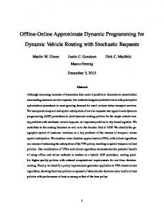
need in their cooperation control. Such a centralized control structure of ABB robot has limited ability and only 4 robots can be involved in 1 cooperative motion maximally. The Independent/Coordinated function of Motoman robot are most flexible in system structure. This flexibility has a direct impact on their instruction format and numbers of controller for their cooperative function. 3. Path planning principle of basic cooperative motion Since aim of this paper is to investigate the OLP techniques for multirobot cooperation system, only the cooperation functions that currently have been provided by robot manufacturers are considered in this paper. To summarize the functions introduced in Section 2, there are only 3 cooperative motions considered here, concurrent cooperation, coupled synchronous cooperation and combined synchronous cooperation. In addition, the discussions here for robot path planning only involve the kinematic aspects. Incorporating dynamics into motion planning still requires further investigation and not mentioned here. 3.1 Classification of basic cooperative motions In reference [14], cooperative motions for multiple robot systems have been classified into three types according to relative motions between end‐effectors of individual robot, which is concurrent cooperation, coupled synchronous cooperation and combined synchronous cooperation. Since cartesian trajectory of cooperative motion in robot joint space is hard to imagine, only cooperations between robots in cartesian space is considered here. A. Concurrent cooperation Irrespective of what motions they have been executing before, a simultaneous motion start time is forced for all robots at synchronization point t 0 . No position or orientation constraints exist in this type of cooperation. B. Coupled synchronous cooperation Irrespective of what motions they have been executing before, a simultaneous motion start time is forced for all robots at synchronization point t 0 . All robots are synchronized and perform identical line or circle arc motions and no relative motion exists between master and slave end‐effectors. The slave robot follows the motions of the master robot, without executing motion blocks of its own. This form of cooperation is mostly used in load sharing task. Figure 1 illustrates a typical two robots cooperative system performing the coupled synchronous cooperation in load‐ sharing mode. In such a cooperation motion, the slave robot requires no separate motion commands of its own because it follows the motion of the master directly. www.intechopen.com
Therefore, path planning problem for a single robot is to identify two robot positions for line motion and three for circle arc motion in robot base frame. However, when it comes to multiple robots cooperation system, things become much more complex.
Figure 1. Two robots cooperating for transportation in coupled synchronous motion.
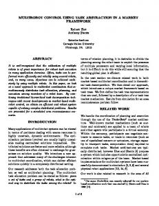
C. Combined synchronous cooperation Irrespective of what motions they have been executing before, an identical motion time is forced for all robots in the synchronization period t. The master robot performs basic line or circle arc motion, while the slaves perform different motion blocks relative to end‐effector frame of master, producing a superposed motion on the basic motion of master robot. The slave robot follows the basic motions of the master robot, but also executes motion blocks of its own. This form of motion is used in process‐dependent mode. Figure 2 shows a typical combined synchronous cooperation of two robots for welding. In such a case, the slave robot processes the workpiece while it is being transferred from one station to another by the master. The master acts as a transportation and positioning robot, while the slave is used as a processing robot. During the transferring process, the master keeps the workpiece constantly in an optimal processing position. The relative position and orientation between the workpiece and tool is retained during motions of the workpiece. Although the above classification may not be exhaustive, it covers the most application cases for industrial process. Most of all, the above 3 cooperation types include all the cooperative functions mentioned in Section 2.
Figure 2. Two robots cooperating for welding in combined synchronous motion.
A typical two robots cooperative system for welding is shown in Figure 3. For such a cooperation system, the path planning problem has many differences with single robot system. First, many cartesian frames exist, such as the absolute world frame, each robot base frame, robot tool frame and some user defined frame. Second, trajectory description for welding robot only distinctly exist relative to workpiece frame, which is a moving dynamic frame. The trajectory description for welding robot in its base frame or absolute world frame is unobvious, which makes the trajectory planning problem beyond capabilities of conventional robot controller. Third, simultaneous motion start/stop and motion synchronization have to be realized between different robot controllers. By far, trajectory planning problem for multiple robot cooperation systems can be formed as following:
3.2 Path planning for coupled synchronous cooperation In conventional robotic systems, path planning is usually carried out in two spaces, the cartesian space and robot configuration space. Robot base frame is the frequently used cartesian space where Continuous‐Path trajectory including line motion and circle arc motion is planned. Robot tool frame and user defined frame also are cartesian spaces, but they are seldom used for single robot system. Robot configuration space is conventionally used in the Point‐To‐Point trajectory planning problem and will not be suitable for arc welding application.
www.intechopen.com
Figure 3. Schematic diagram of two robots cooperative system for welding.
Yahui Gan, Xianzhong Dai and Dongwei Li: Off-Line Programming Techniques for Multirobot Cooperation System
7
Cooperative path planning for a multiple robots system is to identify one robot as master and the other as slaves, determine two cartesian positions for line motion and three cartesian positions for circle arc motion in master base frame for master robot. For coupled synchronous cooperation, no further information needs to be collected for slaves. For concurrent cooperation or combined synchronous cooperation, determine two cartesian positions for line motion and three cartesian positions for circle arc motion in slave base frame for slave robots. After that, plan nominal trajectories in configuration space for each robot by these collected information to achieve cooperative motions between master and slave. In the above 3 cooperation types, no motion constraints exists for concurrent cooperation. Therefore, cooperative path planning strategy is not needed for this type of cooperation. In the following part, the cooperative path planning problem is only investigated for the rest two cooperations, coupled synchronous cooperation and combined synchronous cooperation. Consider two robots, each with n joints, handling a voluminous rigid body object (as shown in Figure 1) that is beyond the payload capacity of any individual robot. To move the object, two robot end‐effectors must grasp it at two specified points. It is assumed that the end‐ effectors furnish tight grips so that there are no relative motions among the end‐effectors and the object. Followed by the definition of Coupled synchronous cooperation, no relative motion exists between master and slave end‐ effectors once their motion have been coupled, which means relative position/orientation between master end‐ effector and slave end‐effector will hold const during the entire period of cooperation. Let the homogenous matrix mb Pm t 44 be the position/orientation of master robot in master base frame and sb Ps t 4 4 be the position/orientation of slave robot in slave base frame at time t. Let coordinates for slave end‐effector in master base frame be mb Ps t 44 , we have
mb
Ps t
mb
Hsb sb Ps t (1)
where mb Hsb 44 is the transformation matrix from slave base frame to master base frame. Once the robots have been mounted, their base will not be changed during the entire period of cooperation. So mb Hsb will be a constant homogeneous transformation matrix during the entire process. Let t0 be the simultaneous start time for mb Pm t and sb Ps t . Let m Hs t 4 4 be the transformation matrix from slave end‐effector to master end‐effector in master base frame at time t 0 , which means 8
mb
Pm 0
m
Hs mb Ps 0 (2)
Int. j. adv. robot. syst., 2013, Vol. 10, 282:2013
Substituting equation (1) into (2) at time t t 0 yields mb
Pm 0
m
Hs mb Hsb sb Ps 0 (3)
By equation (3), we have m
Hs
mb
Pm 0
sb
Ps 0
1
sb Hmb (4)
As the definition of coupled synchronous cooperation, m Hs will be hold constant during the entire period of coupled synchronous cooperation, which means mb
Pm t
m
Hs mb Ps t
Hs mb Hsb sb Ps t
m
mb
Pm 0
sb
mb
Pm
sb
0
P 0 Ps 0
1
sb H mb mb Hsb sb Ps t
1
sb Ps t
s
(5)
By equation (5), we have
sb
Ps t
sb
Ps 0
mb
Pm 0
1
mb Pm t (6)
Equation (6) expresses the holonomic constraints for the position and orientation between master and slave robots during their coupled cooperation motion. This equation also implies that the slave trajectory sb Ps t in its base frame can be uniquely determined in terms of the master trajector mb Pm t and relative position/orientation mb Pm 0 at the initial time of coupled cooperation. This equation establishes the theoretical foundation of our cooperative path planning method for coupled synchronous cooperation. 3.3 Path planning for combined synchronous cooperation Consider two robots cooperate for a jigless welding process as shown in Figure 2. Here, the master robot holds the workpiece while the slave holds a processing tool. In such a case, motion trajectory for master robot must be specified beforehand. Whereas, slave trajectory can not be specified directly and it must be determined by the processing requirement in order to achieve a cooperative motion which is a combined one. Usually, the processing requirement can only be given in workpiece frame. It is supposed that no relative motion is allowed when the master robot holds the workpiece. In such a supposition, processing requirement can also be specified or converted to the master endeffector frame because a constant transformation matrix exists between the workpiece frame and master end‐effector frame. Constraint relations for such cooperative motions of the master‐slave robots will then be different from that of the coupled case. Unlike the constant relation in the above case, a definite time‐varying constraints of the processing requirement must be retained during the combined cooperation. www.intechopen.com
Let mb Pm t be the motion trajectory for master robot in its base frame. Let me Ps t be the processing requirement in master end‐effector frame, which is also the slave motion trajectory in master end‐effector frame. By robot inverse kinematics, trajectory representation mb Pm t can be converted to master joint space for executing the motion. While the slave trajectory me Ps t must be converted from the master end‐effector frame to slave base frame in order to execute the motion. By homogeneous transformation, we have
sb
Ps t
sb
H mb mb H me t me Ps t (7)
where sb Hmb is the transformation matrix from master base frame to slave base frame, mb H me t is the transformation matrix from master end‐effector frame to master base frame. As the definition of robot forward kinematics, mb H me t is the inverse of me H mb t , the position/orietation of robot end‐effector in its base frame,
mb
Hme t
me
Hmb t
1
mb
Pm t
1
(8)
Substituting (8) to (7) yields,
sb
Ps t
sb
Hmb
mb
Pm t
1
me Ps t (9)
Equation (9) expresses the holonomic constraints for the position and orientation between master and slave robots during their combined cooperation motion. This equation also implies that the slave trajectory sb Ps t can be uniquely determined in terms of counterpart mb Pm t of the master and task processing requirement me Ps t . This equation establishes the theoretical foundation of our cooperative path planning method for combined synchronous cooperation.
processes that provide explicit support to multiple robots cooperative motions. For consistency, basic assumptions for cooperative programming are the same adopted as described in the previous sections. That is, a. Instructions must be provided which allow the user to specify the role of each robot or device involved in the cooperation process. Each robot or device must be identified as a master or slave. A master often plays the role of holding and moving the workpieces, such as a positioning table or transporting robot. A slave often plays the role of task processing on the workpieces, such as a welding robot, a spraying robot and so on. b. Instructions must be provided which achieve the cooperative motions between master and slaves. These cooperative motions include all the previously mentioned types, concurrent cooperation, coupled synchronous cooperation and combined synchronous cooperation. A general structure of instructions for cooperative programming is presented in reference [15]. Inspired by their proposal, prototype instructions for our classification are presented here, which is developed and different from reference [15]. These specific instructions for cooperative robot motions can be realized as an incremental part for traditional robot controllers. Figure 4 shows the function blocks for cooperative motion package as an incremental part for traditional control systems of industrial robot.
4. Software architecture 4.1 Extended prototype instructions for cooperative motion The theoretical development in the above sections is a necessary step to achieve the cooperative path planning and job programming for multiple robots cooperative systems. However, traditional programming languages for industrial robot are usually oriented towards single robot operation. In order to realize the above mentioned three cooperations, concurrent cooperation, coupled synchronous cooperation and combined synchronous cooperation, present robot programming languages need to be extended. For this aim, an extension of a prototype programming language has been devised here by defining a set of high level instructions to support the above cooperations for master‐slave robots. This is also a main pathway to foster the application of multiple robots systems in industrial www.intechopen.com
Figure 4. Function blocks for cooperative motion package.
In the following, for the sake of clarity, instructions of cooperative robot control are classified into three distinct subsets. 4.1.1 Instructions for cooperation setting This set of instructions is used to construct or release a multiple robots cooperative system. A component can be
Yahui Gan, Xianzhong Dai and Dongwei Li: Off-Line Programming Techniques for Multirobot Cooperation System
9
added or removed from the cooperative system by such instructions. When a component is added, its role must be specified as master or slave at the same time. Prototype instructions are listed below, SETCOOP [ID_STRING] [Rbt1, Rbt2, , RbtN] [Role1, Role2, , RoleN] or ADDCOOP [ID_STRING] [Rbt1, Rbt2, , RbtN] [Role1, Role2, , RoleN] Here, ID_STRING is a user specified command name, Rbt1, Rbt2, , RbtN is the robot names involved in the cooperative process, Role1, Role2, , RoleN is the corresponding roles for each robot, and values for Role1, Role2, , RoleN must be MASTER or SLAVE . The instruction RELEASECOOP [Rbt1, Rbt2, , RbtN] FROM [ID_STRING] removes the specified components Rbt1, Rbt2, , RbtN from the cooperative set specified as ID_STRING. 4.1.2 Motion instructions for noncooperative robots Instructions in this subset are executed only by robots not declared as cooperative. They are usually used to program movements to be executed independently from the other components in the cooperative set. Usually, they are already part of the standard instruction set of industrial robot programming languages, and are presented here only for the sake of completeness. They can command a joint space motion or a cartesian space motion. Prototype instructions for joint space motion are MOVJOINT [POS] VEL=[VAR]
and MOVAXES [POS] VEL=[VAR]
which realize a point to point motion in joint space. Here, argument POS is the joint position destination to be reached, argument VAR specifies the joint velocity during the motion. Difference between instructions of MOVJOINT and MOVAXES lies in that the former is used for 6 DOF robot while the latter for 1 or 2 DOF devices such as a positioning table. Prototype instructions for cartesian space motion are MOVLIN [POS] VEL=[VAR] [FLYBY]
10 Int. j. adv. robot. syst., 2013, Vol. 10, 282:2013
and MOVCIRC [POS, VIA] VEL=[VAR] [FLYBY]
which realize a continuous linear or circular path in cartesian space. Here, argument POS is the cartesian position destination to be reached, argument VIA is the via cartesian position for circular path, argument VAR specifies the path velocity during the motion. FLYBY is an optional argument which indicates that with FLYBY the robot will go through this intermedius position without stopping while without FLYBY it will stop. 4.1.3 Motion instructions for cooperative robots Instructions in this subset are to start a cooperative motion between multiple robots. The instrcution
CONCURRENT [ID_STRING] [R1, R2, , Rn] [WAIT/NO_WAIT] is to start the previously mentioned concurrent cooperation process. Here, ID_STRING is a user specified command name, R1, R2, , Rn is the robot names involved in this cooperative process. The WAIT option causes the robot to wait on reaching this command until all the other robots have reached this command. The NO_WAIT option causes the robot not to wait on reaching this command but merely to communicate its arrival to the other robots and the robot continues its path motion without interruption.
The instruction COUPLED [ID_STRING] [Rs1, Rs2, , RsN] TO [Rm]
is to start the previously mentioned coupled synchronous cooperation process. Here, ID_STRING is a user specified command name, Rs1, Rs2, , RsN is names of slave robots and Rm is name of master robot. Numbers of slave robots can be single or multiple, but number of master robot must be single per one COUPLED command.
The instruction COMBINED [ID_STRING] [Rs1, Rs2, , RsN] TO [Rm]
is to start the previously mentioned combined synchronous cooperation process. Here, ID_STRING is a user specified command name, Rs1, Rs2, , RsN is names of slave robots and Rm is name of master robot. Numbers of slave robots can be single or multiple, but number of master robot must be single per one COMBINED command.
The instruction
RELEASECOOP [Rbt1, Rbt2, , RbtN] FROM [ID_STRING] www.intechopen.com
has already been defined above. It can also be used here to release the cooperative process defined by the three commands CONCURRENT, COUPLED, and COMBINED.
Motion instructions for single/noncooperative robot have to be modified here to realize cooperative motions defined by the above three commands CONCURRENT, COUPLED, and COMBINED. They are list as,
4.2 OLP software architecture of multirobot cooperation system The above prototype instructions for multirobot cooperation are devised for bridging the simulated 3D visual environment to real robots. Key steps of the software realization are presented in Figure 5. Part of the class hierarchies for multirobot OLP system is shown in Figure 6.
MOVJOINT [POS] VEL=[VAR] COOP=[ID_STRING] [Rbt] MOVAXES [POS] VEL=[VAR] COOP=[ID_STRING] [Rbt] MOVLIN [POS] VEL=[VAR] [FLYBY] COOP=[ID_STRING][Rbt] MOVCIRC [POS, VIA] VEL=[VAR] [FLYBY] COOP= =[ID_STRING] [Rbt]
in which, the augmented argument ID_STRING is the user specified command name defined by CONCURRENT, COUPLED, or COMBINED, argument Rbt is the robot name that specifies the controller group for this instruction.
Figure 5. Key steps of the software realization.
Figure 6. Part of the class view of the OLP software. www.intechopen.com
Yahui Gan, Xianzhong Dai and Dongwei Li: Off-Line Programming Techniques for Multirobot Cooperation System
11
3D CAD Model: This step is to prepare the 3D CAD models of robots and environment setups. These CAD models should be standardized and used universally in different 3D CAD design softwares, like Pro/E, UG, SolidWorks, etc. Nowadays, commercial industrial robot manufactures always provide CAD models of their robots in their product introduction webpages, including ABB, KUKA and Motoman. These models are collected and involved in our research work. As for robot tools and the other setups, their CAD models need to be sketched in the aforementioned CAD design softwares. Kinematic Modeling: This step is to make clear relations between robot joint positions and robot tool postures. Forward kinematics and inverse kinematics of every robot need to be figured out in this step. The only difference of robot kinematic modeling between a single‐robot OLP and a multirobot OLP lies in that robot base frames relative to absolute world frame must be calibrated beforehand and involved in these kinematic equations. Cooperative Path Planning: This step is an unique part of multirobot OLP softwares. Strategies of cooperative path planning have already been presented in Section 3 of this manuscript. This step is to calculate cooperative cartesian path for master and slave robots by equation (6) or equation (9) with robot teach points. Motion Planning: This step is to calculate joint trajectory for each robot. Strategies used in this step are the same with single robot OLP softwares. Simulation: This step is to show a 3D animation of robot motions. Techniques of robot 3D animation used in this step are the same with single robot OLP softwares. Calibration: This step is to make up errors between the simulated environment and the real world. This calibration step includes robot base frame calibration, robot tool calibration, workpiece calibration and so on. Techniques used in this step are also the same with single robot OLP softwares. Real Robot: This step is to download robot jobs generated by the OLP software into real robot controllers. There are usually some standard communication interface (or software) for robot job download, such as Motocom SDK or KUKA.Sim pro.
program [16]. SolidWorks is an outstanding 3D entity design and modeling software. It is easy‐to‐use and has good performance in 3D visualation and simulation. Besides that, SolidWorks allows secondary development of the SolidWorks Application Programming Interface (API), which you can use to automate and customize the SolidWorks software. SolidWorks API contains hundreds of functions that you can call from Visual Basic 6.0, Visual Basic for Applications (VBA), Visual Basic .NET, Visual C# .NET, Visual C++ 6.0, Visual C++ .NET, or SolidWorks macro files. These functions provide direct access to SolidWorks functionality such as creating a line, inserting an existing part into a part document, or verifying the parameters of a surface. Here, the Microsoft ® Visual C++ 6.0 is adopted as the programming tool in our research work.
Figure 7. Multirobot OLP programme developed with SolidWorks ® 2010
5. Software realization result For further illustration and testification of the above presented discussions, an OLP software for multirobot cooperation system is realized and result of the realization is presented here. 5.1 Cooperative system configuration and workcell layout In the first step of the procedure, the graphical simulation of industrial robots, processing tools, workpiece and workspace is achieved using the SolidWorks ® 2010 SP2 12 Int. j. adv. robot. syst., 2013, Vol. 10, 282:2013
Figure 8. Software modules of the developed multirobot OLP programme www.intechopen.com
SolidWorks r 2010 in our lab is shown in Figure 7. Figure 8 is the software modules of our developed OLP programme for multirobot system. Figure 9 shows the simulated graphics of workcell layout of exemplary ABB robots and Motoman robots in our OLP software. 5.2 Job files for cooperative motion and its simulation
Figure 9. Simulated graphics of workcell layout in our OLP software. (a) 2 ABB robots and a positioner; (b) 4 ABB robots; (c) 2 Motoman robots and a positioner; (d) 3 Motoman robots
In this part, the above proposed cooperation instructions are organized into job files to realize the aforementioned 3 cooperative motions. In the following part, Motoman HP20 and VA1400 robot are selected as the exemplary robots for considered cooperation process. Both of the two robots are widely‐used and high‐performance industrial robots. Photographs of the two robots and their kinematic models are shown in Figure 10. Denavit‐ Hartenberg parameters of the two robot are shown in Table 5 and 6 respectively.
Table 5. DH parameters for Motoman HP20 robot
Table 6. DH parameters for Motoman VA1400 robot
Figure 10. Motoman HP20 and VA1400 robot. (a) Photograph of HP20, (b) Kinematic model of HP20, (c) Photograph of VA1400, (d) Kinematic model of VA1400.
Since SolidWorks programm supports many file format of 3D entities, like IGES(*.igs), STEP(*.step,*.stp), STL(*.stl), VRML(*.wrl), etc, these file format for robots, tools, and workpiece can also be supported in our developed OLP software. This character makes our software open to most industrial robots and easy be connected to other 3D entities software designed results. The developed multirobot OLP programme with www.intechopen.com
For coupled synchronous motion, consider the example of two robots cooperating for such a process: Firstly, a transportation task is considered for the two robot HP20 and VA1400. At first, the two robot move to their home positions concurrently and prepare for the transportation task. Then, they move to the grasp positions by point to point motion in joint space. After that, coupled synchronous motions are executed for both robots, including line path and circular path. After the workpiece being transported to its destination, the two robots will be released from the coupled cooperation process. Using the instruction set developed in the previous section, the assigned task can be programmed via the following code:
Yahui Gan, Xianzhong Dai and Dongwei Li: Off-Line Programming Techniques for Multirobot Cooperation System
13
SETCOOP testcoop1 HP20, Master, VA1400, Slave CONCURRENT testcoop1 HP20,VA1400 WAIT
MOVJOINT homepos1 VEL=30% COOP=testcoop1 HP20 MOVJOINT homepos2 VEL=30% COOP=testcoop1 VA1400 RELEASECOOP testcoop1 COUPLED testcoop2 VA1400 TO HP20 MOVLIN pos1 VEL=100mm/s COOP=testcoop2 HP20 MOVCIRC pos2,viapos2 VEL=100mm/s COOP=testcoop2 HP20 RELEASECOOP testcoop2
Figure 11. Snapshot of combined synchronous cooperation by two Motoman robots, HP20 and VA1400.
14 Int. j. adv. robot. syst., 2013, Vol. 10, 282:2013
www.intechopen.com
Figure 12. Time evolution of the joint position and joint velocity for Motoman HP20 robot
Figure 13. Time evolution of the joint position and joint velocity for Motoman VA1400 robot.
In this programm section, only one motion instruction for master robot HP20 is able to produce two robot motions during the coupled synchronous cooperation. As the above mentioned, motions of the slave robot VA1400 must be calculated automatically after motions of master robot HP20 being taught in order to achieve the coupled motion. Secondly, a welding task is considered for the two robot HP20 and VA1400. At first, the two robot move to their home positions concurrently and prepare for the welding task. Then, they move to the welding positions by point to point motion in joint space. After that,
www.intechopen.com
combined synchronous motions are executed with HP20 robot moves in line path and VA1400 robot moves in line path and circular path with respect to the workpiece. In this process, HP20 robot is identified as the master which holds the workpiece and transports it from one workstation to another. VA1400 robot is identified as the slave which carries out the welding task. After the welding process being finished, the two robots will be released from the combined cooperation. Using the instruction set developed in the previous section, the assigned task can be programmed via the following code:
Yahui Gan, Xianzhong Dai and Dongwei Li: Off-Line Programming Techniques for Multirobot Cooperation System
15
SETCOOP testcoop1 HP20, Master, VA1400, Slave CONCURRENT testcoop1 HP20,VA1400 WAIT MOVJOINT homepos1 VEL=30% COOP=testcoop1 HP20 MOVJOINT homepos2 VEL=30% COOP=testcoop1 VA1400 RELEASECOOP testcoop1 COMBINED testcoop3 VA1400 TO HP20 MOVLIN pos1 VEL=50mm/s COOP=testcoop3 HP20 MOVLIN pos2 VEL=65mm/s COOP=testcoop3 VA1400 MOVLIN pos3 VEL=50mm/s COOP=testcoop3 HP20 MOVCIRC pos4, viapos4 VEL=40mm/s COOP=testcoop3 VA1400 RELEASECOOP testcoop3
In this programm section, individual motion instruction for both master robot HP20 and slave robot VA1400 need to be specified. As the above mentioned, motions of the slave robot VA1400 needs to be calculated based on both path information of the master and slave in order to achieve the combined motion. Snapshot of the motion animations for the two robots cooperation process is presented in Figure 11. For clarity reason, a square board with a red circle mark has been mounted at the end of HP20 robot. Trajectory of the tool‐ centerpoint for VA1400 robot in the task space has be marked by a green curve while trajectory of the tool‐ center‐point for HP20 robot in the task space has be marked by a red curve in Figure 11. This cooperative motion animation shows a combined cooperation process, in which HP20 moves along a straight line while VA1400 moves around a circle on the board at the end of HP20 robot simultaneously. Time evolution of the joint position and joint velocity for Motoman HP20 robot with respect to Figure 11 are shown in Figure 12(a) and Figure 12(b) respectively. Time evolution of the joint position and joint velocity for Motoman VA1400 robot with respect to Figure 11 are shown in Figure 13(a) and Figure 13(b) respectively. These data in Figure 12 and 13 are all generated by our simulated robot path planner in the multirobot OLP software. 6. Conclusion Techniques of devising an OLP software for multirobot cooperation systems are investigated in this paper. The discussion is focused on special issues encountered by multiple robot cooperation process. These issues can be recognized as an augmented part of the conventional OLP softwares to make them support not only single robot but also multiple robots systems.
16 Int. j. adv. robot. syst., 2013, Vol. 10, 282:2013
Special issues presented in this paper for multirobot cooperation system include cooperation motion analysis, cooperative path planning strategy, cooperative instructions design and cooperative motion simulation. It is believed that these investigated techniques will promote researches of OLP software development for multirobot cooperation systems. Only basic problems have been touched in this paper. Technique details to design an OLP software support multirobot cooperation for commercial use still need to be clarified in our further research. 7. Acknowledgements This work was supported by the National Natural Science Foundation of China under Grant No.61175113, National High Technology Research and Development Program of China under Grant No.2009AA043903‐1‐1, No.2007AA 041703, Research Innovation Program for College Graduates of Jiangsu Province under No. CX10B_076Z and Scientific Research Foundation of Graduate School of Southeast University under Grant No.YBPY1302. 8. References [1] Siemens Product Lifecycle Management Software Inc. Robotics and automation workcell simulation, validation and off‐line programming [EB/OL]. http://www.plm.automation.siemens.com/zhcn/ products/tecnomatix/roboticsautomation/robcad/ index.shtml, avaliable 2012.10.6 [2] Dassault Systemes. DELMIA Digital Manufacturing & Production [EB/OL]. http://www.3ds.com/products/delmia/,avaliable 2012.10.6 [3] Applied Computing & Engineering Ltd. CimStation Robotics [EB/OL]. http://acel.squarespace.com/cimstation‐robotics, avaliable 2012.10.6
www.intechopen.com
[4] ABB Robotics Corpration. RobotStudio Overview [EB/OL]. http://www.abb.com/product/seitp327/78fb236cae7e6 05dc1256f1e002a892c.aspx, avaliable 2012.10.6 [5] KUKA Roboter GmbH. KUKA.Sim Pro [EB/OL]. http://www.kuka‐robotics.com/en/products/software/ kukasim/kuka sim detail/PS KUKA Sim Pro.htm, avaliable 2012.10.6 [6] Yaskawa Motoman Robotics. MotoSim EG‐VRC [EB/OL]. http://www.motoman.com/products/software/default. php, avaliable 2012.10.6 [7] P. Neto, J.N. Pires, A.P. Moreira. Robot path simulation: a low cost solution based on CAD. in: Proc of 2010 IEEE Conference on Robotics Automation and Mechatronics (RAM), pp. 333‐338, 2010. [8] S. Mitsi, K.‐D. Bouzakis, G. Mansour, D. Sagris, G. Maliaris. Off‐line programming of an industrial robot for manufacturing. International Journal of Advanced Manufacturing Technology, 26(3):262C267, 2005. [9] W.X. Zhang, F.S. Zou, D.K. Qu, F. Xu. Research of key technologies on 3D simulation system of industrial robot. in: Proc of 7th World Congress on in Intelligent Control and Automation (WCICA 2008), pp. 565‐568, 2008.
[10] W.M. Shen, J. Gu, Y.D. Ma. 3D Kinematic Simulation for PA10‐7C Robot Arm Based on VRML. in: Proc of 2007 IEEE International Conference on Automation and Logistics (ICAL 2007), pp. 614‐619, 2007. [11] ABB Robotics. ABB Robotics Application manual: MultiMove, Document ID: 3HAC021272‐001, Revision: K, 2007. [12] KUKA Roboter GmbH. KUKA.CR Motion Cooperation 2.1 For KUKA System Software (KSS) 5.3/5.4/5.5. Issued: 21 Aug 2007, Version: 00. [13] Yaskawa Motoman Robotics. NX100/NXC100 Options: Instructions for Independent/ Coordinated control function. Manual NO. RE‐CKIA443, 2004. [14] Y.H. GAN, X.Z. DAI, J. LI. Cooperative Path Planning and Constraints Analysis for Master‐Slave Industrial Robots. International Journal of Advanced Robotic Systems, Vol. 9, 88: 1‐13, 2012. [15] F.Basile, F.Caccavale, P.Chiacchio, J.Coppola, C.Curatella. Task‐oriented motion planning for multi‐arm robotic systems. Robotics and Computer‐ Integrated Manufacturing, 2012.28(5):569−582. [16] Dassault Systemes. SOLIDWORKS TUTORIALS [EB/OL]. http://www.solidworks.com/sw/resources/solidworks‐ tutorials.htm, avaliable 2012.10.6
www.intechopen.com
Yahui Gan, Xianzhong Dai and Dongwei Li: Off-Line Programming Techniques for Multirobot Cooperation System
17