(2004). 3. J. Fink, N. Michael, S. Kim and V. Kumar Planning and control for cooperative ... S. Wilson, T.P. Pavlic, G.P. Kumar, A. Buffin, S.C. Pratt and S. Berman.
OuijaBots: Omnidirectional Robots for Cooperative Object Transport with Rotation Control using No Communication Zijian Wang, Guang Yang, Xuanshuo Su, and Mac Schwager
Abstract We propose a distributed force and torque controller for a group of robots to collectively transport objects with both translation and rotation control. No explicit communication among robots is required. This work goes beyond previous works by including rotation control and experimental demonstrations on a custom built robot platform. We prove that follower robots can synchronize both their forces and torques to a leader (either a robot or human) that guides the group, and thus contribute positively to the transport. We introduce a custom-designed omnidirectional robot platform, called the OuijaBot, with sensing and actuation capabilities for cooperative manipulation. Our approach is verified by experiments with four OuijaBots successfully transporting and rotating a payload through a narrow corridor. Keywords: Multi-Robot Manipulation, Cooperative Mobile Manipulation
1 Introduction Multi-robot cooperative manipulation and object transport is an emerging field [1, 2, 3, 4, 5, 6, 7] that exploits the power of collaboration among a team of robots to move objects that are too large and heavy for any single robot to handle alone. Most work in this area has focused on controlling the translation of the object, and leaves the rotation of the object uncontrolled. However, rotation control is also an important part of cooperative transport. Rotation control is necessary in reaching an Zijian Wang and Mac Schwager Department of Aeronautics and Astronautics, Stanford University, Stanford, CA, USA e-mail: {zjwang, schwager}@stanford.edu Guang Yang and Xuanshuo Su Department of Mechanical Engineering, Boston University, Boston, MA, USA e-mail: {gyang101, sxs99}@bu.edu
1
2
Zijian Wang, Guang Yang, Xuanshuo Su, and Mac Schwager
appropriate orientation to navigate through spatially constrained environments, for example, when the robots must transport a long object through a narrow corridor. In this work, we propose a novel solution for multi-robot cooperative manipulation, with a particular concentration on rotation control. The feature of our approach is that no communication is required between any two robots, yet the robots have to contribute positively to both the object’s translation and rotation motion. The robots coordinate themselves by sensing the linear and angular velocity of the object, and then applying a force and torque to reinforce the sensed motion. A leader (either a robot or human), who is the only one in the group that knows the destination or desired trajectory, can steer the entire group by adjusting its input. In our previous work [4, 8, 9], we verified that translation can be controlled without communication by properly designing the robots’ forces. In this paper, we extend our prior work by incorporating rotation sensing and torque input, so that the orientation of the object can be independently controlled along with the translation. The main challenge in combining rotation and translation control is due to the complexity of the object dynamics and the kinematics of joint motion of the robotsobject assembly. Our method naturally takes into account both the dynamics and kinematics, leading to a provably convergent and physically realizable approach. In order to verify our algorithm, we introduce a new robot platform for cooperative manipulation called the OuijaBot. The OuijaBot platform is custom designed to realize the sensing and actuation required for our force and torque controller. Our approach is successfully verified in experiments with four OuijaBot robots carrying a loaded pallet, with rotation being controlled in order to go through a narrow passage.
1.1 Related Work Our work has been inspired by the multi-disciplinary research on cooperative transport in robotics and in cooperative ant behavior in biology. A multi-robot system was utilized in [1] to move furniture under different sensing and communication configurations. A formation-based approach called caging was studied in [2, 12], where the robots move the object by maintaining a formation to trap the object as if in a cage. An important issue in multi-robot manipulation is impedance control [13, 14], which has been used to regulate internal forces [15] among multiple manipulators. Massive manipulation experiments were done by [16] with up to 100 robots using flocking. The kinematic multi-robot motion controller proposed in [17] is capable of both translating and rotating the object, by specifying the robots’ speeds with respect to the centroid of the object. There are also approaches that achieve cooperative manipulation without communication, using vision occlusion [7], passive caster [18], and inter-robot force measurements [19, 20]. In addition to the robotics research, the behavior study of ant colonies also backs our assumption that ants use measured motion information for cooperative object transport [21], and that ants tend to align their manipulation forces during collective tranport behaviors [22].
OuijaBots for Cooperative Object Transport
3
2 Problem Formulation We consider manipulation in a 2D environment Q ⇢ R2 , potentially cluttered with obstacles. The object has a mass M and moment of inertia J. The acceleration of the gravity is g, and points downward, perpendicular to the environment plane. The object is subject to two kinds of friction from the ground, kinetic friction and viscous friction, whose coefficients are µk and µv respectively. There is a fleet of N robots, indexed as {R1 , R2 , · · · , RN }. We choose R1 as the leader robot, and others as the followers. Only the leader knows the destination or desired trajectory for the object. The followers do not know where the object needs to be transported, nor the control actions of other robots. The robots are attached to the object, and can apply 2D forces to the object, denoted by {F1 , F2 , · · · , FN }, as well as 1D torques about the z-axis (using the standard right hand rule) represented by {T1 , T2 , · · · , TN }. As the robots cannot communicate, they rely on their sensors to determine what forces and torques to apply. We require the robots to be able to measure the linear and angular velocity of the object, denoted by vc and w. A more detailed sensing model for the robots will be introduced in Section 3.1. Under the manipulation inputs from the robots, the object can translate and rotate in Q. The translation dynamics is governed by Newton’s second law, N
M v˙ c = Â Fi i=1
µv vc
µk Mg
vc , kvc k
(1)
where vc denotes the linear velocity of the object at the center of mass. The rotation dynamics, while the object is in motion, can be written as N
N
i=1
i=1
J w˙ = Â Ti + Â ri ⇥ Fi
µv Jw, M
(2)
where the position vector ri points from the center of mass of the object to the attachment point of robot Ri . The derivation of the rotational dynamics can be found in our previous work [4], where we have shown that the friction model in (2) is linearly damped by µv Jw/M. The objective of this paper is to design a communication-free controller for the robots’ forces and torques, Fi and Ti , so that the robots can guide the objects’ linear velocity vc and angular velocity w to navigate the object along a desired trajectory. Furthermore, only the leader (be it a robot or a human) knows this desired trajectory. In order to achieve the coordination with no communication, we need a few assumptions for the robots, which are summarized below. Assumptions 1. All robots know the value of M, J, µk , µv , g, N, which correspond to the mass of the object, moment of inertia of the object, coefficients of friction, acceleration of gravity, and the number of robots, respectively; 2. Every robot Ri knows its own position relative to the object’s center of mass, ri ;
4
Zijian Wang, Guang Yang, Xuanshuo Su, and Mac Schwager
3. The robots’ attachment points are centrosymmetric around the center of mass of the object, meaning that for any robot Ri , there exists another robot j 6= i such that ri = r j . Note that Assumption 1 can be achieved by existing distributed parameter estimation approaches [10]. The position information in Assumption 2 can also be estimated online by the robots in practice, for example, by using the pipelined consensus algorithm from our previous work [11]. We require Assumption 3 for our convergence analysis, since when force coordination is achieved (i.e., all Fi are equal), the resultant ÂNi=1 ri ⇥ Fi = 0 in (2). In practice, our controller is sufficiently robust to tolerate some lack of centrosymmetry.1
3 Distributed Force and Torque Controller Design 3.1 Robot Sensing Our controller requires the follower robots to measure the linear and angular velocity of the object, denoted as vmi and w mi , where the subscript “m” refers to “measured” and i specifies the robot Ri . Theoretically, w mi should be the same for all the robots since we assume the robots are rigidly attached to the object. However, vmi will be different for all the robots if the object is rotating, since the robots can only measure the velocities at their local attachment points, which can be characterized by vmi = vc + w ⇥ ri .
(3)
In addition to velocity sensing, the robots are also equipped with force and torque sensors in order to perform feedback control, so that the desired force and torque specified by the high-level controller (Section 3.3) can be achieved. The measured force and torque of robot Ri are denoted by fmi and tmi .
3.2 Robot Kinematics We must deal with both the dynamics and kinematics of our combined robot-object system. On one hand, the movement of the object is governed by the dynamics (1), (2). On the other hand, the robots are physically connected to the object, resulting in complex interactions between the object and the robots. Our approach aims to take into account both kinematics and dynamics involved in the process. Many previous approaches for multi-robot manipulation use differential-drive robots, which suffer from non-honolomic constraints when moving with the object 1
Even though strict centrosymmetry is hard to achieve, when the number of robots is large with respect to the size of the object, it is likely that the robots will spread evenly around the object, so that the centrosymmetry can be nearly satisfied.
OuijaBots for Cooperative Object Transport
5
as a whole system. To effectively reduce the complexity involved in this joint motion, the OuijaBots that we present in this paper feature holonomic dynamics using an omni-directional wheel design. Therefore, for our robots the 2D linear velocity, denoted by vdi , and angular velocity, denoted by w di , can be independently controlled, where the subscript “d” means “desired” and i refers to a specific robot Ri . Another advantage of the holonomic configuration is that the force and torque generated by the robot can be controlled independently. As was done in [6], we characterize the force/torque generation by the tendency of the robot to move/rotate faster or slower than the object. The larger this tendency is, the greater the resultant force/torque will be and vice versa. Mathematically, we characterize this tendency as the difference between the commanded (or desired) velocity of the robot and the actual velocity of the object. Thus, we use a linear model to describe this phenomenon, as follows, vdi = vmi + K f (Fi fmi ), (4) w di = w mi + Kt (Ti
tmi ),
(5)
where Fi and Ti are the desired force and torque, respectively, of robot Ri , and fmi and tmi are the measured force and torque, respectively. The parameters K f and Kt are constants that need to be tuned experimentally. Using (4) and (5), the resulting velocity command vdi and w di can be implemented by the robot’s motion controller (i.e., generate motor voltages to fulfill the desired velocities), so that the desired force and torque can be generated. The physical realization of vdi and w di , as well as how to measure vmi and w mi , will be presented in detail in Section 4, where we introduce the hardware design and control system of our OuijaBots.
3.3 Force and Torque Controller 3.3.1 Follower’s Controller Our motivation in designing the follower’s controller is that every robot should be equally responsible for 1/N share of the effort to overcome the friction or resistance of the motion. Thus, the torque controller for the followers can be written as, ✓ ◆ 1 vc (t) Fi (t) = µv vc (t) + µk Mg , i 2 {2, 3, · · · , N}. (6) N kvc (t)k Since vc is not directly measurable, using (3) we can rewrite (6) as ✓ ◆ 1 vmi (t) w mi (t) ⇥ ri Fi (t) = µv (vmi (t) w mi (t) ⇥ ri ) + µk Mg , N kvmi (t) w mi (t) ⇥ ri k
(7)
which can be computed by all the robots since they either know or can measure the quantities in (7). Similarly, the torque controller is defined as
6
Zijian Wang, Guang Yang, Xuanshuo Su, and Mac Schwager
Ti (t) =
µv J w mi (t), i 2 {2, 3, · · · , N}. NM
(8)
Note that in (8), the possible resistance from the term ÂNi=1 ri ⇥ Fi in (2) is not included. We show in Theorem 1 below that we can safely ignore this term under Assumption 3. Even when this term is not equal to zero, a PI controller on the leader’s torque input will effectively reject this disturbance. A quick observation reveals that the controllers (7), (8) themselves imply no communication and rely on only local measurements. The outcome of (7), (8), Fi (t) and Ti (t), can be used by (4), (5) to generate appropriate motor commands. Also note that (7), (8) require no global reference frame information. The sensing and force/torque actuation can all be performed in the robots’ local reference frames. 3.3.2 Leader’s Controller The goal of the leader robot is to steer the group towards the destination or follow a pre-defined trajectory by adjusting its own force and torque input. Suppose that we already know the desired linear and angular velocities from a higher-level path planning algorithm.2 Then we define the leader’s force controller as follows, F1 (t) = fd
vd (t) , kvd (t)k
(9)
where vd is the desired velocity, and fd = K1 max{kvd (t)k = K1 max{kvd (t)k
kvc (t)k, 0} kvm1 (t) w m1 (t) ⇥ r1 k, 0},
(10)
where K1 is a proportional gain. The philosophy behind the leader’s force controller is as follows. From (9) it can be seen that the leader aligns its force along the direction of vd , which tends to drag the object’s velocity towards vd . The magnitude of F1 is determined by a proportional controller (10), aiming to reduce the difference between kvd k and kvc k. The max function is used to ensure that F1 does not point opposite to vd . The torque controller of the leader is T1 (t) = K2 e(t) + K3 s (t),
(11)
where K2 is the proportional gain, K3 is the integral gain, and s˙ (t) = e(t) = w d (t)
w m1 (t).
(12)
The rotation controller (11) is essentially a PI controller that drives the angular velocity of the object to the desired w d . 2
There are many off-the-shelf algorithms we can choose, and this is not the focus of this paper.
OuijaBots for Cooperative Object Transport
7
3.3.3 Convergence Proof Theorem 1. Using the followers’ force/torque controller (7), (8) and the leader’s force/torque controller (9), (11), the object’s linear and angular velocity, vc and w track vd and w d as a first order filter. Furthermore, if vd and w d are constant, and assuming negligible measurement noise w mi = w, 8i, vc and w converge asymptotically to vd and w d . Proof. For force convergence and the convergence of vc to vd , refer to Lemma 1 and Theorem 1 in our previous work [9], where similar proof procedures can be applied. For rotation, if noise is not present in the sensing, we have w mi = w, 8i 2 {1, 2, · · · , N}. Then plugging the followers’ torque inputs (8) into the rotation dynamics (2) yields 1 1 N 1 µv w˙ = T1 + Â ri ⇥ Fi w. (13) J J i=1 NM If we treat w as the state and T1 as the input, (13) is a stable first-order linear system with ÂNi=1 ri ⇥ Fi /J as the disturbance, which we know will diminish to zero when the force convergence is achieved under the centrosymmetric assumption. Furthermore, given a constant desired angular velocity wd , the leader’s torque input (11) implements a PI controller with w d as the set point. Therefore, we know that w will converge to w d [23]. t u Note that in (13), the followers’ torque inputs help reduce the magnitude of the resistence significantly. Also, in the steady state of (13), the torque inputs from all the robots (including the leader) are equal.
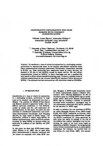
4 OuijaBot Hardware and Control System We designed and manufactured an omnidirectional robot platform, named OuijaBot, which brings together unique sensing and actuation capabilities to implement the controllers proposed in the previous section, as shown in Figure 1. The OuijaBot contains four symmetrically-placed omnidirectional wheels, with free rollers along the perimeter that enable sideways movements. The wheels are independently driven by four DC motors, each of which is rated at 5A stall current under 12V, generating a maximal torque of 0.78Nm. Encoders are mounted with the motors to measure the velocity. We designed a custom Printed Circuit Board (PCB) for low-level motor control and processing sensor measurements, including encoders, motor currents, accelerometer, gyroscope, and magnetometer. A Raspberry Pi is used as a more powerful computation hub and for running the Robot Operating System (ROS). OuijaBot weighs 2.7kg and can move up to 1m/s. For cost and complexity considerations, OuijaBot currently does not have a suspension system, which is left for future work. Instead, we test our robots mainly on a resilient surface with plastic mats, to help alleviate the suspension problem.
8
Zijian Wang, Guang Yang, Xuanshuo Su, and Mac Schwager
(a)
(b)
Fig. 1 Our custom-built omnidirectional robot platform called OuijaBot. (a) The overall appearance. Four brushed DC motors are mounted symmetrically underneath the chassis. Battery and all electronics are enclosed compactly inside the aluminum shell. The top layer of the robot can be used to install additional equipment, such as a gripper, robotic arm, camera, or lidar as shown in this picture. (b) Our PCB design. The low-level microcontroller is an ARM Cortex-M4 running at 100MHz. Four motors are driven by four full H-bridges through PWM signals. The motor currents are measured using four Hall effect current sensors. Other sensors including encoders, 9-axis IMU are also handled by the Cortex-M4. Various interfaces such as Serial, I2C, SPI, and PWM are reserved for connecting future add-on devices.
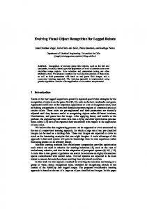
4.1 Motion Control Given a desired linear vdi and angular velocity w di , as computed by (4), (5), the robot needs to realize the velocity by controlling the speeds of its four wheels. A schematic of the motors and wheels are shown in Figure 2. We denote the output angular velocity of the wheel as w i , i 2 {1, 2, 3, 4}. We assume that each wheel is controlled by the corresponding motor in the nominal direction, while free to slide sideways. Then the mapping from the wheel speeds to the robot speed is p 2rw vdi = [w 3 w 1 + w 4 w 2 , w 3 w 1 + w 2 w 4 ]T , (14) 4 w di =
(w 1 + w 3 )rw (w 2 + w 4 )rw = , 2rB 2rB
(15)
where rw is the radius of the wheel and rB is the radius of the robot. Note that in (15), we impose an additional artificial constraint since four wheels are redundant in generating the 3-DOF velocity. Using (14) and (15), we have four equations to uniquely determine four wheel speeds. Standard PID controllers are implemented on the PCB to handle the motor control and achieve the required wheel speeds w 1 , w 2 , w 3 , w 4 .
OuijaBots for Cooperative Object Transport !B
!1rw, I1
!4rw, I4
9 !2rw, I2
yB M1
M2
M4
M3
xB
rB
!3rw, I3
Fig. 2 Configuration of OuijaBot’s motors and wheels. M1-4 are the four motors. The positive directions of different quantities are as marked. We choose the body-frame xB and yB axis as such because these are the two directions in which the robot can generate the maximal amount of force, and also move at the highest speed.
4.2 Velocity Measurement and Traction Control The wheel speeds are measured by four encoders mounted on the back of the motors. In order to measure vmi , as required in (4), (7), (10), we can use the same kinematic equation in (14) and substitute w 1 4 with the measured wheel speeds. In order to measure w mi , as used in (5), (7), (8), (12), the reading from the gyroscope is used rather than solving (15) since this is a more accurate approach. A possible factor that may degrade the accuracy of measuring the linear velocity is the wheel slipping along the nominal direction. We use a practical approach for detecting wheel slippage and to enhance traction control, similar to what has been done in the automobile industry. In every detection period (200ms in our case), we calculate the robot velocity using the encoder readings using (14), (15). In parallel, we also estimate the linear velocity by integrating the acceleration, and the angular velocity by reading the gyroscope, using IMU data. If the difference between the two sets of measurements exceeds a pre-defined threshold, then the robot knows that slipping occurred and then tries to reduce speed to regain traction.
4.3 Force and Torque Measurements The torque generated by each motor can be measured by the current sensor through the linear relationship T = Ki I, where Ki is a coefficient. Denote I1 , I2 , I3 , I4 , along directions shown in Figure 2, as the effective current of each motor corrected with the no-load current, then the force and torque generated by the robot with respect to the center of the mass, as required by (4)(5), can be measured as p 2Ki rw fmi = [ I1 I2 + I3 + I4 , I1 + I2 + I3 I4 ]T , (16) 2 tmi = Ki rw rb (I1 + I2 + I3 + I4 ).
(17)
10
Zijian Wang, Guang Yang, Xuanshuo Su, and Mac Schwager
5 Simulation We have successfully verified our distributed force and torque controller first in simulation using Open Dynamic Engine (ODE), a well-known physics engine in the robotics community. Twenty robots are employed to transport a simulated chair which weighs 2kg. The task setup is visualized in Figure 3, and the goal is to navigate the chair through the narrow corridor on the right. Since the opening of the corridor is smaller than the length of the chair, the robots have to rotate the chair by 90 degrees. The robots are placed symmetrically around the chair, each of which is able to apply force and torque calculated by (7), (8) or (9), (11). In this simulation we focus on the force and torque rather than the specific mechanics of the robot, so we visualize the robots as spheres. The leader, drawn in blue and located at one corner of the chair, is the only that knows the desired destination and orientation of the object. During the entire process, no communication occurs between any two robots. Additionally, in order to simulate the noisy sensing and actuation, the force and torque applied by the robots are corrupted by zero-mean Gaussian noise.
(a) Initial position
(b) Intermediate position
(c) End position
Fig. 3 Twenty robots successfully transport and rotate a chair to cross a narrow corridor in simulation. The leader robot is drawn in blue while follower robots are in yellow. The robots use the communication-free force and torque controller described in Section 3.
The forces and torques of the robots are plotted in Figure 4, where the leader’s steering on the followers’ forces and torques is evident. The trajectory of the object is shown in Figure 5. For the purpose of comparison, we place the trajectory in the simulation next to that of the experiment (Section 6), where the task objective is similar. The two trajectories present resemblance to each other in terms of reaching the desired x and q value, and holding the position in y direction (the offset value does not matter).
6 Experiments Our approach is validated experimentally using four OuijaBots. The scenario of our experiment is shown in Figure 6. Four OuijaBots are rigidly attached to the corners of a piece of square wood (0.6m ⇥ 0.6m), together serving as a modular pallet system. The imagined payload, three round bars, are fixed onto the pallet.
OuijaBots for Cooperative Object Transport
11
Fx 1
Force / N
0.8 0.6
0.5
0
5
10 Time / s Fy
15
0.4
Torque / Nm
0
Force / N
Leader Torque
Leader Fx
0.2 0
Leader Fy
0.5 0
−0.2
−0.5 0
5
10 Time / s
−0.4 0
15
5
(a) Robots’ Forces.
10 Time / s
15
(b) Robots’ Torques.
Fig. 4 The forces and torques of the robots during the simulation. The leader’s force and torque are in bold black lines, while the other lines correspond to the followers. Despite the noises, it is clear that all the followers respond and follow the trend of the leader’s input.
4
x (m) y (m) θ (rad)
4
3
3
2
2
1
1
0 0
x (m) y (m) θ (rad)
0
5
10 Time / s
15
(a) Trajectory in simulation.
0
5
10
15 20 Time / s
25
30
(b) Trajectory in experiment.
Fig. 5 Trajectory of the object in simulation (left) and experiment (right). In both cases, the robots are successful in transporting the object along x direction, and rotating the object by 90 degrees. The displacements on y axis in both cases are maintained around zero (the offset values are not meaningful), which ensure the desired straight line motion to the right side.
The goal of the experiment is to first track a straight line to move the pallet towards the right of the field, which is about 4.5m away, and then cross the narrow corridor between the two piles of boxes. As shown in Figure 6(a), the initial orientation of the pallet cannot go through the corridor since the length of the bar is larger than the opening of the corridor. Therefore, the robots must rotate the pallet before reaching the corridor, as shown in the final moment in Figure 6(d). Upon the start of the experiment, all the robots are issued the same initial speed to establish the initial movement3 . After that, all the follower robots perform all the sensing and computation as described in Section 3 and 4 completely onboard with3
Initial movement can be also triggered without communication using random trials [4]. For the sake of clear presentation, we skip this phase, which is not the focus of this paper.
12
Zijian Wang, Guang Yang, Xuanshuo Su, and Mac Schwager
(a) t = 0
(b) t = 10s
(c) t = 20s
(d) t = 33s
Fig. 6 Snapshots of the cooperative transport experiment. The locations of the robots are marked in (a). The robots are able to move the pallet to the right side and also rotate 90 degrees counterclockwise in order to go through the narrow corridor. The experiment video is available online at https://youtu.be/4nLMYjqUoJ4.
out any inter-robot communication. The leader’s controller (9), (11) is implemented offboard by integrating the external positioning information from Vicon4 , which is consistent with our assumption that only the leader knows the desired trajectory. The actual trajectory of the object is plotted in Figure 5. The forces and torques applied by all the robots are shown in Figure 7, which are recorded at 100Hz. The plots indicate that the follower robots share a large amount of the force in order to help the leader overcome the friction. Also, the torque inputs from the followers tend to follow the changes of the leader’s torque, and are mostly positive, verifying the followers’ contribution to help rotate the object counterclockwise. Moreover, our approach allows the leader’s force and torque to be from a human. We verify this by letting a human operator control the leader robot using a joystick to carry out the same task, while the follower robots run the same program as before. Due to the space limit, this result is shown in the online video: https://youtu.be/4nLMYjqUoJ4.
7 Conclusion and Future Work In this paper, we present a decentralized force and torque controller for a group of robots to control both the translation and rotation of an object during cooperative manipulation without communication. We show theoretically and in hardware ex4
http://www.vicon.com/
13
20
2
15
1
Torque / Nm
Force / N
OuijaBots for Cooperative Object Transport
10
Leader R2 R3 R4
5
0
0
10
20
30
Time / s
(a) Magnitude of robots’ forces
0
Leader R2 R3 R4
-1
-2
0
10
20
30
Time / s
(b) Torques applied by the robots
Fig. 7 Forces and torques applied by the robots during the transport process. The plots confirm that the follower robots contribute positively to the manipulation.
periments that the robots can rely on their measurements of the object’s motion to coordinate their force and torque inputs, rather than using explicit communication. We designed and built a new omni-directional robot platform, the OuijaBot, and successfully validated our approach in real time experiments with four OuijaBots cooperatively transporting a loaded pallet. In the future, we plan to leverage machine learning to estimate parameters such as M, µk , µv , N, ri online. Also, we are interested in more advanced filtering on the multi-sensor data, and extending our approach to the 3D using aerial robots. Acknowledgements This work was supported by NSF grant CNS-1330036, and also by the Toyota-SAIL Center for AI Research. The authors are grateful for this support.
References 1. D. Rus, B. Donald and J. Jennings. Moving furniture with teams of autonomous robots.In Proceedings of the International Conference on Intelligent Robots and Systems (IROS), vol. 1, pp. 235–242. (1995) 2. G.A. Pereira, M.F. Campos and V. Kumar. Decentralized algorithms for multi-robot manipulation via caging. The International Journal of Robotics Research, vol. 23(7-8), pp. 783–795. (2004) 3. J. Fink, N. Michael, S. Kim and V. Kumar Planning and control for cooperative manipulation and transportation with aerial robots. The International Journal of Robotics Research, vol. 30(3), pp. 324–334. (2011) 4. Z. Wang and M. Schwager. Multi-robot manipulation without communication. In Proc. of the International Symposium on Distributed Autonomous Robotic Systems (DARS), Daejeon, Korea, 2-5 November, pp. 135–149. (2014) 5. S. Wilson, T.P. Pavlic, G.P. Kumar, A. Buffin, S.C. Pratt and S. Berman. Design of ant-inspired stochastic control policies for collective transport by robotic swarms. Swarm Intelligence, vol. 8(4), pp. 303–327. (2014)
14
Zijian Wang, Guang Yang, Xuanshuo Su, and Mac Schwager
6. J. Alonso-Mora, R. Knepper, R. Siegwart and D. Rus. Local motion planning for collaborative multi-robot manipulation of deformable objects. In Proceedings of the IEEE International Conference on Robotics and Automation (ICRA), pp. 5495–5502. (2015) 7. J. Chen, M. Gauci, W. Li, A. Kolling and R. Groß. Occlusion-based cooperative transport with a swarm of miniature mobile robots. IEEE Transactions on Robotics, vol. 31, no. 2, pp. 307–321. (2015) 8. Z. Wang and M. Schwager. Multi-Robot Manipulation with no Communication Using Only Local Measurements. In Proceedings of the IEEE International Conference on Decision and Control (CDC), pp. 380–385. (2015) 9. Z. Wang and M. Schwager. Kinematic Multi-Robot Manipulation with no Communication Using Force Feedback. In Proceedings of the IEEE International Conference on Robotics and Automation (ICRA), pp. 427–432. (2016) 10. A. Franchi, A. Petitti and A. Rizzo. Decentralized parameter estimation and observation for cooperative mobile manipulation of an unknown load using noisy measurements. In Proceedings of the IEEE International Conference on Robotics and Automation (ICRA), pp. 5517– 5522. (2015) 11. G. Habibi, Z. Kingston, Z. Wang, M. Schwager and J. McLurkin. Pipelined consensus for global state estimation in multi-agent systems. In Proceedings of the International Conference on Autonomous Agents and Multiagent Systems (AAMAS), pp. 1315–1323. (2015) 12. J. Fink, M.A. Hsieh and V. Kumar. Multi-robot manipulation via caging in environments with obstacles. In Proceedings of the IEEE International Conference on Robotics and Automation (ICRA), pp. 1471–1476. (2008) 13. S. Erhart, D. Sieber and S. Hirche. An impedance-based control architecture for multi-robot cooperative dual-arm mobile manipulation. In Proceedings of the International Conference on Intelligent Robots and Systems (IROS), pp. 315–322. (2013) 14. M.D. Kennedy, L. Guerrero and V. Kumar. Decentralized algorithm for force distribution with applications to cooperative transport. In ASME International Design Engineering Technical Conferences and Computers and Information in Engineering Conference. (2015) 15. D. Williams and O. Khatib. The virtual linkage: A model for internal forces in multi-grasp manipulation. In Proceedings of the IEEE International Conference on Robotics and Automation (ICRA), pp. 1025–1030. (1993) 16. M. Rubenstein, A. Cabrera, J. Werfel, G. Habibi, J. McLurkin and R. Nagpal. Collective transport of complex objects by simple robots: theory and experiments. In Proceedings of International Conference on Autonomous Agents and Multi-agent Systems (AAMAS), pp. 47–54. (2013) 17. G. Habibi, Z. Kingston, W. Xie, M. Jellins and J. McLurkin. Distributed Centroid Estimation and Motion Controllers for Collective Transport by Multi-Robot Systems. In Proceedings of the IEEE International Conference on Robotics and Automation (ICRA), pp. 1282–1288. (2015) 18. D.J Stilwell and J.S. Bay. Toward the development of a material transport system using swarms of ant-like robots. In Proceedings of the IEEE International Conference on Robotics and Automation (ICRA), pp. 766–771. (1993) 19. R. Groß, F. Mondada and M. Dorigo. Transport of an object by six pre-attached robots interacting via physical links. In IEEE International Conference on Robotics and Automation (ICRA), pp. 1317–1323. (2006) 20. R. Groß and M. Dorigo. Group transport of an object to a target that only some group members may sense. In International Conference on Parallel Problem Solving from Nature, pp. 852– 861. (2004) 21. H.F. McCreery and M.D. Breed. Cooperative transport in ants: a review of proximate mechanisms. Insectes Sociaux, vol. 61(2), pp. 99–110. (2014) 22. S. Berman, Q. Lindsey, M.S. Sakar, V. Kumar and S. Pratt. Study of group food retrieval by ants as a model for multi-robot collective transport strategies. Robotics: Science and Systems (RSS), pp. 259 – 266. (2010) 23. H.K. Khalil. Nonlinear systems. Second Edition. Prentice Hall New Jersey. (1996)