Yao-Ming Yeh, Member, IEEE, and Tse-yun Feng, Fellow, IEEE. Abstract-Benes networks are known as the nonblocking re- arrangeable networks which can ...
1361
IEEE TRANSACTIONS ON COMPUTERS, VOL. 41, NO. 11, NOVEMBER 1992
On a Class of Rearrangeable Networks Yao-Ming Yeh, Member, IEEE, and Tse-yun Feng, Fellow, IEEE
Abstract-Benes networks are known as the nonblocking rearrangeable networks which can realize arbitrary permutations without conflict. In this paper, we introduce a class of 2 log, N stage networks which are equivalent to the Benes networks. Networks in this class can be either symmetric or asymmetric in their structure, regular or irregular in their inter-stage connections, and even, 2 log, N or 2 log, N - 1 stages. All networks in this class are nonblocking rearrangeable. A switch labeling scheme is proposed to provide testing the topological and functional equivalency for this class of networks. This switch labeling scheme can also provide a novel matrix representation for network configuration. This new representation introduces a portability concept for the routing scheme on this class of networks. With this new representation, a general routing scheme is also developed. This routing scheme can realize arbitrary permutation for the whole class of 21og, 3 stage networks. Index Terms-Benes networks, functional equivalence, general routing scheme, rearrangeable networks, switch labeling scheme, topological equivalence, 2 log, .Y stage networks.
I. INTRODUCTION
A
MULTISTAGE interconnection network (MIN) is rearrangeable if it can realize arbitrary permutation between input and output terminals. The three-stage Clos network [5] is known as a rearrangeable network. Consider the networks with 21og, N stages: It is well known that a baseline-baseline-' network (i.e., the Benes network [3]) can be constructed from the concept of three-stage Clos network. It is also known that an omega-omega-' network [SI is a rearrangeable network which is equivalent to the Benes network. However, not every 210g, N stage network has the same capability as the Benes network and is equivalent to it. For example, it is still unknown whether an omega-omega network is a rearrangeable network or not. Apparently, to determine if a network is a rearrangeable network is the main issue for the class of 2 lo& N stage networks. In this paper, a general model for a class of networks which is equivalent Benes networks is proposed. It can be used to determine the rearrangeability of a 2 lo& N stage network. A partial comparative study on the network equivalence of 2 log, N stage networks can be found in the literature. Wu and Feng [17] proved the equivalence of six log, N stage networks and showed that they have the same routing capability. Afterwards, they [181 extended their equivalent properties to show that two-pass of a reverse exchange network (i.e., the baseline-'-baseline-l network) has the same routing Manuscript received September 10, 1991; revised January 22, 1991. Y.-M. Yeh is with the Department of Information and Computer Education, National Taiwan Normal University, Taipei, Taiwan, R.O.C. T. Feng with the Computer Engineering Program, Department of Electrical and Computer Engineering, The Pennsylvania State University, University Park, PA 16802. lEEE Log Number 9202619.
capability and is equivalent to the Benes network. Lee [8] proposed a routing scheme for the omega-omega-' network and proved that it is a rearrangeable network. Huang and Tripathi [7] proposed a finite state model for permutation networks and also showed that a baseline-'-baseline-' network is equivalent to the Benes network. In these works, the authors discussed the equivalence relations among the class of 210g, N stage networks case by case. There is no general model which can describe the whole class of networks which are equivalent to the Benes network. This paper proposes a switch labeling scheme for the class of 21ogb N stage networks, for any b. This scheme can lead to a general model for the class of 2 lo&,N stage networks. The switch labeling scheme consists of two steps: outside-in and inside-out decompositions. These two steps can generate an outside-in and inside-out codes, respectively, for every switch in the network. With these codes, a large class of networks which are equivalent to the Benes network is defined. These codes also provide a new representation on the network configuration for this class of networks. This new representation introduces a new aspect to the routing scheme of these rearrangeable networks. In the literature, the routing schemes proposed for the class of 2 lo& N stage networks are mainly focused on baselinebaseline-l networks. Waksman [16] proposed a routing algorithm which uses matrix decomposition procedure for the Benes network. Opferman and Tsao-Wu [13], [14] proposed the looping algorithm for the Benes networks. Andreson [2] extended the looping algorithm to base 2t networks. Lee [SI, [9] suggested a different view on the routing of the baselinebaselineF1 and the omega-omega-' networks. She applied decomposition on the input half of the network and used selfrouting on the output half of the network. All above algorithms have the computation time complexity of O ( N log, N ) . To speed up the routing on the Benes networks, Lev et. al. [lo] parallelized the edge coloring algorithm on bipartite graph to realize the routing on the Benes networks. Nassimi and Sahni [12] proposed a parallel version of Waksman's scheme to set up the Benes network. The above two algorithms reduce the computation time to O((log, N ) , ) . All these existing schemes provide routing on predefined networks, there is no general routing scheme for the whole class of 2 logb N stage networks. These existing routing schemes have a common feature in that they implement the network configuration into the implicit control sequence of their routing scheme. The routing on different networks should support with different control mechanisms. As a result, the routing scheme for a baselinebaseline-' network is not applicable for an omega-omega-' network. Thus, they are not portable among networks. Owing
0018-9340/92$03.00 0 1992 IEEE
1362
only provide the routing of symmetric networks such as the baseline-baseline-’ and the omega-omega-’ networks. With the help of our switch labeling scheme, we introduce the concept of portability to the routing of the rearrangeable networks. A general routing scheme is developed to support the portability among the whole class of 2 log, N stage networks. This paper is organized as follows: Section I1 describes a
nection network is developed. This model provides a new representation for both one stage of switches and an interstage connection. We identify some new properties from the existing inter-stage connections. With these properties, a switch labeling scheme is proposed to describe the pattern of an inter-stage connection. This scheme helps to represent various types of inter-stage connections and introduce new inter-stage connection patterns for MIN’s. This model is the foundation of forming the classes of lo& N and 2 log, N stage networks.
A. A Stage of Switches A ( b x b ) switch is a crossbar component which can realize arbitrary connection between its input and output ports. For an ( N x N ) stage network using ( b x b ) switches, a stage of switches can be viewed as a device to realize certain permutations of N numbers from 0 to N - 1 located between these switches’ input and output ports. These N numbers are equally divided into Nlb segments by these switches as defined below. Definition 1: A Complete Segment Partition N and b, denoted by C S P ( N ,b), is a partition of N ordered numbers (i.e., 0 , 1 , . . . , N - 1) into N / b equal size segments with each segment having b contiguous numbers. Therefore, each segment is a Residue Class mod b, denoted by R C ( N ,b). From the interconnection network point of view, a R C ( N ,b ) represents the input or output ports of a ( b x b ) switch within a stage. For example, let N = 8 and b = 2, there are four RC(8,2)’s: (0, 1}, {2,3}, {4,5}, {6,7}. These four RC(8,2)’s represent the input or output ports of switches in a stage: So, 5’1, 5’2, and 5’3 respectively. In other words, a switch boundary is referred to as a R C ( N ,b ) boundary or a segment boundary of a sequence of numbers. Definition 2: In an ( N x N) interconnection network, a stage of ( b x b) switches can realize a class of segment permutations of N and b, denoted by E:. It is a permutation
IEEE TRANSACTIONS ON COMPUTERS, VOL. 41, NO. 11, NOVEMBER 1992
o
x
1 x
2 3 4
5
X X X X
6
7
X X
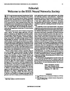
of N numbers (i.e., 0,1, . . . , N - 1) which divides its inputoutput pairs into Nlb segments of size b and do arbitrary permutation on each segment. Therefore, when the control setting of every switch on a stage is decided, the permutation realized by this stage of switches is a segment permutation, denoted by F p ( C ) ,where C is a vector of control bits for the switches in this stage. The relation between E: and F t ( C ) is F t ( C ) E E:. From the above definition, a switch boundary within a stage is referred to as a segment boundary within a segment permutation. The input and output numbers in a segment are corresponding to the input and output ports within a switch. For example, the segment permutation F:(C), where C = (1,1,1,0), is shown as below
Ft(C)=
(
0 1 2 3 4 5 6 7 1 0 3 2 5 4 6 7 .
)
In a (2 x 2) switch, if the control bit is 0, the switch goes “through;” if the control bit is 1, it goes “cross.” A permutation can be represented in a relation table, with its input numbers as columns and output numbers as rows in the table. Therefore, F;(C) can be represented with a relation table as shown in Fig. 1. Note that the grid boundaries in Fig. 1 denote the switch boundaries. Lemma 1: A segment permutation E: is a permutation group. Proof: A permutation group has closure, identity, inversion, and associative properties [11]. It is trivial to show that a segment permutation E: satisfies these four properties. See [20] for detail. 0 The relation table can also represent a segment permutation. For example, E; is shown in Fig. 2. From this figure, four rows (or columns): (0, l}, { 2 , 3 } , {4.5}, {6,7} form equivalence classes [11];they are also segments and switches. The switch boundaries are also indicated in Fig. 2.
1363
YEH AND FENG: CLASS OF REARRANGEABLE NETWORKS
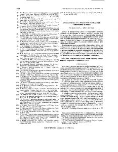
B. An Inter-stage Connection If we look into the inter-stage connections in the existing MIN’s [ 171 such as baseline, omega, and data manipulator (i.e., SW banyan S=F=2), we can find the same scramble property: the upper and lower output ports of each switch in one stage are connected to distinct switches in the next stage. Therefore, for a network using ( 2 x 2) switches, when a set of N terminals from the output ports of previous stage passes to the input ports of next stage, it is decomposed into two disjoint sets of N / 2 terminals, one containing the terminals from the upper output port of each switch in the previous stage, the other containing the terminals from the lower output port of each switch in the previous stage. This property holds for every inter-stage connection such as shuffle (i.e., g y , o;,. . . , gE-l), unshuffle (i.e., ( c T ~ ) - ’ , ( U ; ) - ’ , . . . , (o;-~)-’),and banyan (i.e., A,; AT, . . . , This scramble property can be formalized by the following definitions. Definition 3: A Complete Residue Partition N and Nlb, denoted by C R P ( N ,Nlb), is a partition of N numbers (i.e., 0,1, ’ .,N - l ) ,which are equally divided into N/b sets such that each set contains exactly one representative from every R C ( N ,b). The derived set is called the Complete Residue System modulo Nlb, denoted as C R S ( N ,Nlb). Among these N numbers, since there are b possible choices to get one representative from each of k R C ( N ,b)’s, bk possible C R S ( N ,k ) ’ s can be formed. Continuing the previous example, two CRS(8,4)’s are derived from the above mentioned four RC(8,2)’s(i.e., (0, l } , {2,3},{ 4 , 5 } ,{ 6 , 7 } ) . Therefore, there are 16 possible ways to perform CRP(8.4) on these 8 numbers. They can be partitioned into {0,2.4,6} and {1,3,5,7},or {1,2,4,6} and {0,3,5,7},etc. In our stage model, we are interested in the special CRP(8,4)which partitions these 8 numbers into {0.2,4, 6} and {1,3,5,7}.It is defined as follows. Definition 4: A regular C R P ( N ,k ) , is a partition of N numbers (i.e., 0 , 1 , . . . ,N - 1) into b C R S ( N ,k ) ’ s such that the ith C R S ( N ,k) contains the ith representative in each R C ( N , b ) , where IC = N / b and k 2 b. The derived C R S ( N , k ) s are called regular C R S ( N , k ) and denoted as C R S ( N , k ) o ,CRS(N,IC)l,. . ., CRS(N,k)b-l. From the above definition, performing regular C R P ( 8 , 4 ) on 0 7 obtains two regular CRS(8,4)s: CRS(8.4)o = {0,2,4,6} and CRS(8,4)1 = {1,3,5,7}. Fig. 3 shows a prototype of an inter-stage connection which has the above mentioned scramble property. From Fig. 3, one inter-stage connection is described by two functions as follows: F1. Perform regular C S P ( N .Nlb) on the input end of the links (i.e., the output ports of the previous stage); therefore, the ith output port of each switch in the previous stage goes to regular C R S ( N ,Nlb),. F2. Assign the elements in every C R S ( N ,Nlb) to the switches in the next stage. Note that the C R S ( N ,Nlb) boundary should be on a switch boundary. In other words, a switch cannot cross two C R S ( N ,N/b)’s. Besides, the switches assigned in each C R S ( N , N / b ) can be any combination from the next stage. N
1. decompose into CRS(N,k)’s
Fig. 3 .
2. assign to input ports of switches
An inter-stage connection: a residue permutation
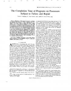
All the existing inter-stage connection patterns such as shuffle and unshuffle are formed from the above two functions. We define a class of permutations to represent an inter-stage connection as below. Definition 5: For a network using ( b x b ) switches, an interstage connection which performs both F1 and F2 functions is called the residue permutation of N and k, denoted by a:. The inter-stage connections used in the proposed MIN’s such as baseline, omega, and SW banyan S=F=2 are residue permutations a:. These inter-stage connections perform both functions F1 and F2. We observed that from the operations in F1 and F2, if an inter-stage connection is a residue permutation a:, then the switches in its next stage can be labeled by the indexes 0 b - 1. These indexes are the regular C R S ( N ,I C ) indexes. Fig. 4 shows the inter-stage connections which are residue permutations. Fig. 5 shows some inter-stage connections which are not residue permutations. N
C. A Single Stage Model The permutation a: describes a residue permutations which can be used as an inter-stage connection in a network using ( b x b) switches. The permutation E: defines a stage of switch control; it is determined after the control setting of each switch is decided. The composition between a? and E: can be defined as a single stage which is the concatenation of a stage of switches and an inter-stage connection. Definition 6: A Full Function stage (FFS) of N terminals is a stage with both permutations a:, and E: concatenated together. Therefore, either E: oa? or a: o E: can be a FFS. With the single stage model defined above, an interconnection network is the concatenation of many FFS’s. Since it was observed that the switches in the next stage of an inter-stage connection can be labeled by indexes 0 b - 1, the labeling pattern can reflect the inter-stage connection pattern. From the operations in F1 and F2, the labeling pattern also describes the paths of the messages from one stage of switches passing through an inter-stage connection and reaching to the next stage. We will use this switch labeling scheme to explore the inter-stage connection pattern and to represent the network configuration. N
1364
IEEE TRANSACTIONS ON COMPUTERS, VOL. 41, NO. 11, NOVEMBER 1992
Fig. 4. The inter-stage connections which are residue permutations.
Fig. 5 . The inter-stage connections which are not residue permutations.
111. A GENERALMODELFOR A CLASS OF 210gbN STAGE NETWORKS A switch labeling scheme is introduced in this section. This scheme can lead to a general model for the class of 2 lo& N stage networks, for any b. The switch labeling scheme consists of two steps: outside-in decomposition, and inside-out decomposition. These two steps can generate an outside-in code and an inside-out code for every switch in the network. With these codes, our general model can define a large class of networks which are equivalent to the Benes networks. These equivalent networks can have either regular or irregular interstage connections, either symmetric or asymmetric structure, and even, either 2 lo&,N or 2 lo& N - 1 stages.
I
Fig. 6 . Outside-in decomposition and three-stage Clos network
A. Outside-in Decomposition The idea of outside-in decomposition is to label the switches based on the subnetwork decomposition layer by layer from outside-in to the center stages. The layers of a network are labeled from 1 to n stage-by-stage from outside-in. For a stage located on layer a (1 5 a 5 n) in input half of the network are denoted as ia, and its reflected stage in output half stage is denoted as oa. The mechanism of outside-in decomposition is derived from the definition of a three-stage Clos network in Fig. 6. To support this mechanism, we can send 2N signals simultaneously from both input and output terminals. These signals propagate through stage by stage until they meet in the center of the network. Initially, each signal carry a label with no value. When a signal traverses through one stage, a value i, 0 5 i 5 b - 1, is attached behind its label according to the following rule:
1
I
Fig. 7. Inside-out decomposition and the complementary Benes network.
RI: Attach i when the signal goes through the ith port of the switch (i.e., consider the output ports for the input half of the network; and input port for the output half). The label of each switch is derived from the label of all its incoming signals. This label is defined as outside-in-code. Fig. 8(a) shows the result of outside-in decomposition on an omega-omegap1 network. The outside-in-code of each switch is indicated within the switch. Definition 7: In a 210gbN stage network, an outside-incode, OC, of a switch in layer m (i.e., either switch Sim,j
1365
YEH AND FENG: CLASS OF REARRANGEABLE NETWORKS
il
i2
i3
i4
04
03
02
01
(4
il
i2
i3
i4
04
03
02
01
(b) Fig. 8. An omega-omega-'
network. (a) Outside-in decomposition. (b) h i d e - o u t decomposition.
or S,,,j, for 0 5 j 5 N - l), is defined as an m digits base b number: OC[1 : m],where 0 5 O C [ k ]5 b - 1 for 1 5 IC 5 m - 1. The value of each digit OC[k]is derived from rule R1. From the definition of the Clos network, an outside-in-code is the label of the decomposed subnetworks. When the signals reach the inner layer, the decomposition continues by attaching value i to the tail of the labels. The effect of subnetwork decomposition can be illustrated more clearly by a baselinebaseline-' network (the Benes network) as shown in Fig. 9(a). We observed that performing outside-in decomposition on a network can help to decide if it is equivalent to a Benes network. Two criteria are developed for this purpose. These criteria are derived from the definition of the Clos network. They are described below. C1. If the incoming signals of a switch have different labels, then this switch cannot form its outside-in-code. This indicates that the network cannot perform subnetwork decomposition as defined by the Clos network; therefore, it is not equivalent to the Benes network.
C2. According to the idea of subnetwork decomposition on the middle stage of the Clos network, signals with the same label should meet on the center of the network. In other words, the inter-stage connection on the center (i.e., the links between the center stages in the input half and the output half) should connect the switches with the same outside-incode. If a network cannot satisfy the above two criteria, it is not an equivalent Benes network. For example, Fig. 10 shows a network which conflicts with criterion C1. This network cannot form its outside-in-code on the switches indicated. Fig. 11 shows that an omega-omega network is also not equivalent to the Benes network because it conflicts with criterion C2. Its center links connect the switches with different outside-incodes. It is easy to identify the subnetworks in a Benes network. However, other networks, such as an omega-omega-' network, have its subnetworks scrambled among one another, which makes them difficult to be identified. With an outsidein-code in every switch of a 21og, N stage network, we can
IEEE TRANSACTIONS ON COMPUTERS, VOL. 41, NO. 11, NOVEMBER 1992
1366
0 1
2 3 4
5 6
7 8
9 10 11
12 13
14 15
il
i2
i3
i4
04
03
02
01
04
03
02
01
(a)
il
i2
i3
i4 (b)
Fig. 9.
A baseline-baseline-'
network. (a) Outside-in decomposition. (b) Inside-out decomposition.
identify its subnetworks by collecting the switches with the same outside-in-code. The collected switch sets indicate the switch decomposition of one stage. This switch decomposition further reflects the subnetworks distribution pattern in the network. We can formalize this switch decomposition effect as the effect of Complete Residue Partition (CRP). Therefore, the collection of the switches with the same outside-in-code forms a set of Complete residue system module Nlb. These switch sets are defined as below. Definition 8: In a 210gb N stage network, a C R S ( N ,Nlb) switch set is the set of switches that have a similar outside-incode. This outside-in-code is the code of this G R S ( N ,Nlb) switch set. A C R S switch set with code x is denoted as CRS,. The size of a C R S ( N ,Nlb) switch set is the number of switches in the set. It is denoted as I C R S , 1. Note that the switches on layer 1 have no outside-in-code value. All of them form a C R S ( N ,Nlb) switch set with no code value, denoted as C R S .
Lemma 2: In a 21og, N stage network, the size of each C R S ( N , N / b ) switch set on layer a is 2 * b"-", where 1 < a < n .
Proofi It can be proved by induction. For a 2 logbN stage network, the number of switches in a stage is bn-l, where n = log,N. Each layer consists of 2 * (b"-') switches if input and output stages are included. On layer 1, all the switches on layer 1 form a C R S ( N , N / b ) switch set. Thus its size is 2 * ( b " - l ) . Assume the size of each G R S ( N ,N / b ) switch set on layer i is 2 * bn-'. The number of C R S ( N ,Nlb) switch sets on this layer is 2 * bn-'/2 * bn-z, which is b"'. We shall prove that on layer i 1, the size of each G R S ( N ,Nlb) switch set is 2 * bn-("') as following: The outside-in-code of every switch in layer i 1 is derived by attaching new digit to the tail of every outside-in-code in layer i according to rule R1. Each switch has b ports; thus, value 0 to b - 1 is attached to
+
+
1367
YEH AND FENG:CLASS OF REARRANGEABLE NETWORKS
0
0
1
1
2
2
3
3
4
4
5
5
6
6
7
7
8
8
9 10
10
9
11
11
12
12
13
13
14
14
15
15
il
i3
i2
i4
04
02
03
01
Fig. 10. A network which conflicts with criterion C1. 0
1 8 9
4 5 12 13 2 3 10 11
6
7 14 15
il
i2
i3
i4
04
03
02
01
Fig. 11. An omega-omega network conflicts with criterion C2.
form the new outside-in-code for all the switches in layer i 1. These new codes divide all the switches in layer i 1 into b * bi-l C R S ( N ,N l b ) switch sets. Therefore, the size of each switch set is 2 * b"-'/b * bi-', which is 2 * b"-(Z+'). As a result, the lemma is proved by i nduction. U
+ +
B. h i d e - o u t Decomposition The operation of inside-out decomposition is like the reflection of outside-in decomposition. Its idea can be described from the definition of the complementary Benes network as shown in Fig. 12. The mechanism of inside-out decomposition is to label the switches layer-by-layer from center stages to both input and output terminals. Similarly, we can send 2N signals simultaneously from the center stage of both sides to propagate through stage by stage until they reach the input or output terminals. Initially, each signal also carries a label with no value. When a signal traverses through one stage, a value i , 0 5 i 5 b - 1, is attached behind its label according to rule R2:
R2: Attach i when the signal goes through the ith port of the switch (i.e., consider the input ports for the input half of the network; and output ports for the output halJ). The label o f each switch is also derived from the label of all its incoming signals. This label is defined as insideout-code. Fig. 8(b) and Fig. 9(b) show the result of insideout decomposition on the omega-omega-' and the baselinebaseline-' networks, respectively. Definition 9: In a 210gbN stage network, an inside-outcode of a switch in layer m (i.e., either switch Sim>j or Som,j, for 0 5 j 5 N l b ) , is defined as an n-m digits base b number: IC[1 : m],where 0 5 IC[k]5 b - 1 for 1 5 k 5 n - m. The value of each digit I C [ k ]is derived from rule R2. With an inside-out-code in every switch including the input and output terminals, two criteria are developed to test the network equivalence to a Benes network: C3. If the incoming signals of a switch have different labels, then this switch cannot form its inside-out code. This indicates that the network cannot perform subnetwork decomposition as
1368
IEEE TRANSACTIONS ON COMPUTERS, VOL. 41, NO. 11, NOVEMBER 1992
0 1
2
3 4 5
6 7 0 9 10 11 12 13
14
15
il
i2
i3
i4
04
03
02
01
04
03
02
01
(a)
il
i2
i3
i4 (b)
Fig. 12. A network which satisfies criteria C1 and C2 but conflicts with criterion C3. (a) Outside-in decomposition. (b) Inside-out decomposition.
defined by the complementary Benes network; therefore, it is not equivalent to the Benes network. C4. The inside-out-codes on both input and output terminals represent the address of these terminals. From the definition of functional equivalence [17], if two networks have the same sequence on their input and/or output terminals, they are functionally equivalent. For example, Fig. 12 shows a network which satisfies criteria C1 and C2 but which conflicts with criterion C3. As a result, it is still not equivalent to the Benes network. Owing to criterion C4, an omega-omega-' network is not functionally equivalent to a baseline-baseline-' network. Up to now, performing outside-in and inside-out decomposition, every switch in a network has two codes in it. These two codes have some relations between them which are described in the following lemma. Lemma 3: In a 210gb N stage network, a C R S ( N ,N / b ) switch set with size k contains the switches with unique insideout-codes values from 0 to (k/2)- 1 in base b representation on each half of the network.
Proof: It is proved by induction. Since the decomposition procedure applies rule R2 inside-out on the network, we also consider the layers of the network from inside-out. In layer n, from Lemma 2, each C R S ( N ,N / b ) switch set contains two switches, one switch on each half of the network. The inside-out-codes of these two switches are no value. Value 0 is assumed for these switches, such that this lemma holds in this boundary condition. Assuming this lemma holds in layer i , we should prove that it still holds in layer i - 1. In layer i , from Lemma 3, the size of each G R S ( N ,N / b ) switch set is 2 * bn-'. Select the switch set CRSo...oo (i.e., the code has i - 1 digits) from this layer. The switches in CRSo.,.oohave distinct inside-out-code from 0 to bn+ - 1 on each half of the network, which are represented in n - i digit base b numbers. Applying rule R2 on these switches will attach one more digit with value 0 to b - 1, which will generate 0 to b * b"-' - 1 distinct inside-outcodes in distinct switches on layer i - 1. From the subnetwork construction of the Clos network, these switches on layer i - 1 form CRSo..., (i.e., the code has i - 2 digits). Similarly, we
1369
YEH AND FENG: CLASS OF REARRANGEABLE NETWORKS
0
1 8
9 4 5
12 13
2 3
10 11 6
7 14
15
can prove that the other C R S ( N ,N / b ) switch sets in layer C1-C3 in outside-in and inside-out decompositions. It is repi - 1 have distinct inside-out-codes from 0 to b"-("') - 1. resented as Thus, it is proved by induction. 0 I o (log, NFFS's) o P o (log,, NFFS's) o 0 C. A General Model for 2 log, N Stage Networks The switch labeling scheme as described previously indicates how every switch in the network is connected to construct a Clos network. From Lemma 2, labeling the outsidein-code on every switch of a 210g, N stage network reflects the subnetwork construction in the network; furthermore, from Lemma 3, labeling the inside-out-code on the switches indicates their relative locations to construct a subnetwork. These principles are extended from the construction of the Clos network, which are similar to the construction of the Benes network. Therefore, with this switch labeling scheme, we define a class of 2 lo&, N stage networks which are equivalent to the Benes network as follows. Definition 10: An equivalent Benes network is a bidirectional ( N x N ) network formed by two lo&, N stage networks back-to-back concatenated together which satisfies criteria
-~
where ( b x b ) switches are used in the network, I denotes input terminals of the network, 0 denotes output terminals of the network, P denotes a permutation which connects the switches with the same outside-in-code from its both sides. A network with 2 log, N - 1stages still can satisfy criteria C1-C3 by assuming two center stages of both halves are overlapped together. This type of networks is called a reduced 2 lo& N stage networks. We can use criteria Cl-C3 to test if the network is topologically equivalent to the Benes network. When the network satisfies criteria Cl-C3, criterion C4 is further used to test if the network is functionally equivalent to the Benes network. For example, Wu and Feng [19] suggested an omega-R-omega network (i.e., R is a partial bit-reverse permutation), as shown in Fig. 13, to prove that 3 log, N - 1stages of shuffle/exchange
IEEE TRANSACTIONS ON COMPUTERS, VOL. 41, NO. 11, NOVEMBER 1992
1370
0
0
1
1
8
8
9
9
4
4
5
5
12
12
13
13
2
2
3 10
3 10
11
11
6 7
6
14
14
7 15
15
i l
i2
i3
i4
04
03
02
01
(a) 0
0
1
1
8
8
9
9
4
4
5
5
12
12
13
13
2
2
3 10
3 10
11
11
6
6
7
7
14
14
15
15
il
i2
i3
i4
04
03
02
01
(b) Fig. 14. A banyan-' -banyan network. (a) Outside-in decomposition. (b) Inside-out decomposition
is rearrangeable. An omega-R-omega network is an equivalent Benes network because it can satisfy criteria C1-C3. Fig. 14 shows a banyan-banyan network; Fig. 15 shows two asymmetric networks: an omega-baseline network and a baseline-omega-' network; Fig. 16 shows a reduced omegaomega-' network. All the above networks are equivalent to the Benes network. 1) Generalized 2logN Stage Networks where N # b": Bhuyan and Agrawal [4] proposed the generalized logN stage networks. The networks they proposed are mixed-base ( N x N ) networks, where N is not the power of any number. A operation of mixed-base switch labeling is extended from our previous switch labeling scheme by using the idea of mixedbase among stages in the networks. A class of generalized 2 log N stage network can be defined according to the mixedbase switch labeling operation. In order to satisfy the definition of the Clos network, criterion C5 should be added to our previous criteria: C.5.The input and output sides of every layer in a network should has the same base. In other words, the types of switches
can be different among layers, but a layer should use the same type of switches on its both input and output sides. Definition 11: A generalized 2 log N stages interconnection network is a bidirectional ( N x N ) network formed by two generalized log N stage networks back-to-back concatenated together which satisfies criteria C1-C3 and C5 when performing outside-in and inside-out decompositions. It is represented as
Io(generalizedlogNFFS's)oPo(generalized log NFFS's)oO where I denotes input terminals of the network, 0 denotes output terminals of the network, P denotes a permutation which connects the switches with the same outside-in-code from its both sides. A network with 2 lo& N - 1 stages still can satisfy criteria C1-C3 by assuming two center stages of both halves are overlapped together. This type of networks is called a reduced generalized 2 log, N stage networks. Fig. 17 shows two types of generalized 210g N stage networks; one is a symmetric network and the other is an asymmetric network.
1371
YEH AND FENG: :LASS OF REARRANGEABLE NETWORKS
i l
i2
i3
i4
04
03
02
01
(4 Fig. 15. Asymmetric-'
networks. (a) A baseline-omega-'
D.A Matrix Representation for 2 lo& N Stage Networks The representation of network configuration is the foundamental research on MIN's. In the literature, Agrawal [ 13 proposed a graph notation for log, N stage networks; Pradham and Kodandapani [ 151 used switching theory formulation for log,N stage networks; Huang and Tripathi [7] suggested a finite state model for 21og, N stage networks. These models tried various ways to represent different types of inter-stage connections in a MIN. Agrawal used directed links, Pradham used switching functions, and Huang used bit-permute operations to represent inter-stage connections. They all tried to include a large number of various interstage connections in their models; however, their attempts make the representation of inter-stage connections as the most complicated part of their models. The switch labeling scheme as described above can be extended to provide a new representation for network configuration. It is a matrix representation which stores the outside-in-codes and inside-out-codes of all switches in the
network.
network. We define two ( N l b ) x (21ogb N ) matrices: an outside-in matrix stores the outside-in-codes and an inside-out matrix stores the inside-out-codes of all switches in the network, respectively. These two matrices are sufficient to represent the network configuration for the class of 2 log, N stage networks. This stems from the operations of outside-in and inside-out decompositions. From rule R1, a stage of outside-in-codes describes how one end of inter-stage links connect to its inner stage; and also, from rule R2, a stage of inside-out-codes indicates how the other end of inter-stage links connect to its outer stage. Therefore these two matrices embed the inter-stage connection patterns in the whole network into switch labels. As a result, inter-stage connections are no longer necessary in our representation. This representation is superior to the existing representations in the following reasons: 1) It is straightforward to be implemented by computer representation.
~
lEEE TRANSACTIONS ON COMPUTERS, VOL. 41, NO. 11, NOVEMBER 1992
1372
il
i2
i3
i4
il
i2
i3
i4
04
03
02
01
04
03
02
01
( b) Fig. 15.
(Continued)(b) An omega-baseline network
2 ) The inter-stage connection pattern of a network is already embedded in outside-in and inside-out matrices; therefore, inter-stage connection pattern is no longer necessary in our representation. 3) It makes the network configuration like a data form rather than a complicate control mechanism; therefore, it can provide the portability of the routing scheme.
Iv. A GENERALROUTINGSCHEME FOR 2 log, N STAGE NETWORKS
A CLASS OF
With the help of our switch labeling scheme, we introduce the concept of portability to the routing on the rearrangeable networks. A general routing scheme is developed to support the portability among the whole class of 210g2 N stage networks. A. Switch Mapping on the Routing Scheme We have shown that the outside-in-codes and inside-outcodes derived from outside-in and inside-out decompositions
can be used to represent the network representation. Outsidein-codes are used to group the C R S ( N ,k) switch sets from the switches of a network. We can further construct a tree structure from these switch sets. The tree can represent the relations among switches and reflect the subnetwork construction of the network. It is defined as below. Definition 12: The C R S ( N ,k) switch sets in an 2 lo& N stage network form a network tree of depth n and degree b, where n = log, N . A network tree is denoted as @(n), where n is the depth of the tree. A node of the network tree is a C R S ( N ,k) switch set. Each node is identified by the code of its C R S ( N ,k) switch set. A level of the tree presents a layer in the network which has one input stage and its reflected output stage. A subtree of the network tree describes a subnetwork of this 2 log, N stage network. A subtree is denoted as Q a ( d ) , where subscript a is its root’s C R S ( N , k ) switch set code and d is its depth. Fig. 18 shows the network trees of some 2 log, N stage networks. Every network tree has a similar structure. The only difference among them is that the switches assigned in
1373
YEH AND FENG: CLASS OF REARRANGEABLE NETWORKS
il
i2
i3
03
4
02
0'
(4
il
i2
i3
4
02
01
( b)
Fig. 16. A reduced omega-omega-' network. (a) Outside-in decomposition. (b) Inside-out decomposition.
each node are arranged based on their outside-in-codes and inside-out-codes. To realize an ( N x N ) permutation request on a network, the permutation with N input-output pairs is placed on the input and output terminals of the network. Each input-output pair has two instances placed on their corresponding terminals, one on the input side and the other on the output side. The mechanism of these input-output pairs passing through layers of the network from outside in has a similar effect as outside-in decomposition, which decomposes these inputoutput pairs into sub-permutations among layers. We define a permutation tree whose structure is isomorphic as a network tree. Definition 13: A sub-permutation is reducible if its inputoutput pairs can be fully assigned to a number of switches.
Therefore, for a network using ( b x b ) switches, a reducible sub-permutation contains the multiple of b input-output pairs (i.e., m * b, where m is the number of switches assigned, and 1 5 m 5 Nlb). From the above definition, a permutation request itself is reducible since it can be fully assigned to N J b switches. Definition 14: An ( N x N ) permutation request for a 2 lo& N stage network forms a permutation tree of depth n and degree 6, where n = lo&, N . A permutation tree is denoted as Q ( n ) ,where n is the depth of the tree. A node of the permutation tree is a reducible sub-permutation. The siblings of a node are the equally decomposed sub-permutations from this node. Therefore, the root of a permutation tree is the permutation request itself. For example, a permutation request is given as following:
0 1 2 3 4 5 6 7 8 9 1 0 1 1 1 2 1 3 1 4 1 5 P = ( 1 0 6 2 1 3 1 4 3 1 5 9 1 2 7 5 14 0 11 8
IEEE TRANSACTIONS ON COMPUTERS, VOL. 41, NO. 11, NOVEMBER 1992
1374
0 1 2
0
3 4 5
3 4 5
6
6
7
7 8
1 2
8 9
9
10 11
10 11 base 3
base2
base2
base2
base2
base 3
0 1 2
0 1 2
3 4 5
3 4 5
6 7 6
6
base3
base2
base2
base2
base2
base 3
base3
base2
base2
base2
base2
base 3
7 6
9
9
10
10 11
11
base 3
base2
base2
base2
base2
base3
(a)
(b)
Fig. 17. The generalized 2 log AVnetworks. (a) A symmetric network. (b) An asymmetric network
It can be decomposed to form a permutation tree as shown in Fig. 19. The procedure to decompose a permutation request is described in the next section. If we look into the same level between the permutation tree and the network tree, the number of input-output pairs in each node of the permutation tree is equal to the total number of ports in each node of the network tree. Therefore, they are not only isomorphic on the structure among nodes but also isomorphic within the nodes. With these two isomorphic trees, to determine the switch setting of a network which can realize the permutation request is to apply a mapping on these two trees. The mapping is performed by assigning the code of a C R S ( N ,K ) switch set to each node in the permutation tree. The mapping of the nodes between the permutation tree and the network tree will in turn provide the mapping of every input-output pair to the ports of every switch. This switch mapping mechanism determines the setting of every switch in the network. The outline of our general routing scheme is shown below. Algorithm 1: routing on a ( N x N ) network using ( b x b ) switches begin Stepl: construct the network tree from outside-in and inside-out matrices; Step2: apply input-output pair decomposition on the permutation request; Step3: construct the permutation tree; Step4: map the permutation tree to the network tree;
Step5: assign the switch settings in the network tree; end. Our routing scheme is applicable for the whole class of 2 log,, N stage networks. Since the network tree is provided by outside-in and inside-out matrices, it acts as the data of the routing scheme. Therefore, this routing scheme can be applied to every network within the class of 2 log, N stage networks. Besides, the existing routing schemes [8], [lo], [12], [13] mainly focused on Step2 only. We can extract the portion of input-output pair decomposition in these schemes and extend them to a general routing procedure by our switch mapping mechanism.
B. Input-Output Pair Decomposition The problem of input-output pair decomposition is similar to edge coloring problem on a bipartite graph. The problem is to assign b distinct labels (or colors) to the b input-output pairs located on each switch such that no conflict occurs in every switch. The condition to avoid conflict is to synchronize the assignment on both input and output sides of each subnetwork such that every input-output pair on both sides could meet itself from the other side in the center of the network. This problem is a combinatorial problem without an optimization requirement. Every complete assignment without conflict is a feasible solution. In this section, we consider the input-output pair decomposition procedure for the networks using ( 2 x 2) switches only.
1375
YEH AND FENG: CLASS OF REARRANGEABLE NETWORKS
level 1:
CRS(16,E)
inside-out-code I O 0 0 1 0 0 1 1 0 1 0 1 0 1 1 I l O O l l O l I 1 l O l 1 1 1 1 I
switch assigned ininputsid witch assigned in ou,,,ut si*
level 2:
level 3:
'i1,2
'i1,3
'i1,4
'il.5
'il,6
'i1,7
'01,l
'01,2
'01.3
'01,4
'01,s
'01.6
'01.7
/\
'i3,O
'i3.1
'03,O
'03,l
CRS( 16,8b,
A
[i 000
I
'i1,l
CRS(16,8)o
CRS(16,8k,,
level 4:
S11.0 S0 1 , O
001
010
100
01 1
101
110
111
'04,O
(4 Fig. 18. The network trees. (a) A baseline-baseline-'
As described in the previous section, our general routing scheme can extract the input-output pair decomposition procedure from the existing schemes and adapt it into Step2 of our algorithm. The existing schemes provide O ( N log, N ) [13], [16] to compute the input-output pair decomposition in sequential time and O((log, N ) , ) [lo], [12] in parallel time. From Algorithm 1, the decomposition result from Step2 is used to construct the permutation tree in Step3. This tree can be built in the manner of either depth-first or breadth-first construction. Most of the existing schemes use breadth-first approach, since once the sub-permutations (the nodes in the permutation tree) of a level are decomposed, the switch settings of its corresponding level in the network tree are determined accordingly. Thus, the algorithm does not need to keep the decomposition results in the higher level. We can use a queue (first-in-first-out list) to implement breadth-first mechanism as shown in Algorithm 2. A procedure queue(p) is used to insert a node to the end of queue; and a procedure dequeue@) is used to delete a node from the head of the queue. Since the network tree is constructed when a network is specified, Step1 of Algorithm 1 is not necessary when the same network is used to realize a new permutation request. Algorithm 2: routing on a ( N x N ) network using (2 x 2) switchesbegin queue(P ) ;
network.
while queue not empty do dequeue ( p p t r) ; decompose(pptr,P O ,PI ); switchsetting( p p t r ) ; if po decomposible then queue(p0); if p l decomposible then queue(p1); endwhile end. The procedure decompose(P,PO,P I ) decomposes a node in the permutation tree, in other words, it decomposes a reducible subpermutation into two siblings. The procedure is extended from the looping algorithm [13]. We should define the buddy relation for input-output pairs before we describe this procedure. Definition 15: In a network, the input or output ports within the same switch are called buddies. If the network uses (2 x 2) switches, the buddy of a is denoted as &. If they are input ports of the same switch, they are called input buddies; if they are output ports, they are called output buddies. For the input-output pairs in a permutation request, they are also called buddies when they share the same switch. Therefore, if they use the input ports of the same switch, they are called input buddies; similarly, they are called output buddies when they use the output ports of the same switch.
IEEE TRANSACTIONS ON COMPUTERS, VOL. 41, NO. 11, NOVEMBER 1992
1376
level 1:
CRS( 16,8)
inside-out-code switch assigned in input side switch assigned in oulpul side
level 2:
'i1,O
'i1,4
'i1,2
'i1,6
'i1,l
'i1.5
'i1,3
'i1,7
'01,O
'01,4
'01,2
'01,6
'01.1
'01,s
'01.3
'01,7
CRS(l6,8)o
CRS(16,8)1
'02,l
level 3:
000
A
001
'02,3
'02,7
J
/
CRS(16,8bo
level 4:
'02,5
H
010
'i3,2
'i3,6
'03,2
'03,6
A
01 1
100
101
110
111
(b)
Fig. 18. (Conrinued) (b) An omega-omega-
' network.
0 1 2 3 4 5 6 7 8 9101112131415 (106213143159127
5 14 0 118
Fig. 19. A permutation tree.
As we described before, a permutation can be represented in a relation table. In a relation table, the input buddy of an inputoutput pair is the other input-output pair in the same column; meanwhile, its output buddy is the other input-output pair in
the same row. In our algorithm, we use inputbuddy(w) and outputbuddy(w) to denote the input and output buddies of an input-output pair w, respectively. Since the label assigned to an input-output pair is either 0 or 1, the binary complement
1317
YEH AND FENG: CLASS OF REARRANGEABLE NETWORKS
0
1 2
3
4
5
6
7 8
9 101112131415
at level 2:
Po0 =
(:b
1
9 0 12 l3
5 4
Po1 =
7
(i
15
10 7
15) 8
-
Each of them are assigned to CRS(16,8)00 CRS(16,8)11, respectively. In level 3 (the center level), the nodes in level 2 are further decomposed into 8 sub-permutations:
) )
0 13 Po00 = (10 0 2 15 polo = ( 2 8 PlOO = 0
1 2
3
4
5
6
7 8
9 101112131415
(; ;)
i13 3
PllO =
11 5 )
Po01 =
(;
;)2)
7 poll = ( 7
10 15)
6 = (3
12 14)
'lo'
4 Plll = ( 1
14 ll).
Algorithm 3: input-output pair decomposition on a ( mx m ) sub-permutation P procedure decompose(P,PO,P I ) ;begin Stepl: for i = 0 to m do { initialization } mark "x" on the relation table for P ( i ) ; endfor Step2: map the switches to each row and column of the relation table; Step3: while some "x"s remain in the relation table do { code assignment } select a "x" as the start point w (i.e., select the first in a column); c t 0 ; { set code 0 } CRS(l6,8) P ( w ) t c; { assign code to input-output pair w } while inputbuddy(w) is unassigned do Fig. 20. Input-output pair decomposition for P. (a) Mark input-output pairs in the relation table (i.e., after Step 1). (b) Code assigned to every input-output w + inputbuddy(w):c E pair (i.e., after Step2) P ( w ) t e: if outputbuddy(w) is unassigned then w t outputbuddy(w);c t C operation is applied on the code variable. Algorithm 4 is P(w) c: described as below, which decomposes an ( m x m ) reducible endif; sub-permutation into two siblings. endwhile; Fig. 20 shows how this procedure decomposes the permuendwhile; tation P given in the previous section. From the assignments Step4: for i = 0 to m do { collect PO and PI } in Fig. 20, P is decomposed into sub-permutations PO and PI if P ( i ) = 0 then Po(j0) t P ( i ) ;j o + j o 1; as shown below if P ( i ) = 1 then P l ( j l ) t P ( i ) ;j l + j l 1; 0 2 5 7 9 1013;) endfor 2 4 15 12 7 0 end. Fig. 21 shows the whole procedure to decompose permutation P and indicates how the network tree of an omega1 3 4 6 8 1 1 1 2 1 4 omega-' network is mapped to the permutation tree. The p1= 6 1 3 1 3 9 5 1 4 1 1 switches mapped to the input-output pairs are specified on where Po is assigned to CRS(16,8)0 and PI to CRS(16,8)1. each column and row of every relation table. Fig. 22 shows From the permutation tree in Fig, 19, these two sub- the switch setting of the whole network. The switch setting of permutations are further decomposed into 4 sub-permutations each switch is derived from its first input-output pair's code "XI'
+ +
(
IEEE TRANSACTIONS ON COMPUTERS, VOL. 41, NO. 11, NOVEMBER 1992
1378
outside-in-code : N I L
Stage i l 0
4
2
6
1
5
3
switch assigned
7
0
Stage 01
1
5
3 7
outaide-in-code : 0 0 0
0
4 2
5
Stage 12 2 9
7
outside-in-code 6
: 1 1 1
101315
0
1
2
3
Stage i2 5 3 3
4
6
8
7
111214
5 6
Stage 02
Stage 02
8
*
9
10
11
12
13
15
14
0
5
4
2
6
3
Stage i3 7
4
Stage03
II
7
4
n
1
2
3
4
5
6
7
Fig. 21. The code assignment of P in an omega-omega-’ network.
assignment: 0 as “through” and 1 as “cross.” The procedure switchsetting(P) supports the operation. For each input-output pair, the code assigned corresponds to the code of the subnetwork into which this input-output pair should go in the inner layer. Therefore, Step2 is referred to as code assignment. Step2 is also the operation to form the loops in the relation table. It sequentially traverses every inputoutput pair in the relation table. Therefore, Algorithm 3 needs O ( N ) to decompose an ( N x N ) permutation. Algorithm 3 can be parallelized to speed up to O(log, N ) from the idea of the proposed schemes by Lev [lo] and Nassimi [12]. Since log, N levels of sub-permutations should be decomposed to determine the switch setting of the whole network, our routing scheme needs O ( N log, N ) in sequential time and O((log, N ) , ) in parallel time. This routing scheme accepts the
network configuration in matrix form; it can be easily switched from one network to another without changing program.
V. CONCLUSIONS A class of 2 log, N stage rearrangeable networks is defined. All networks in this class are equivalent to the Benes network and provide nonblocking routing for arbitrary permutation. In this class of network, a new representation for network configuration is also devised from our new switch labeling scheme. A test procedure based on four criteria is also developed to determine if a network with 2 lo& N stages is in this class. Besides, a general routing scheme, which is portable among this class of networks, is also developed from our new representation. This routing scheme needs O ( N log, N ) in sequential time and O((log, N ) , ) in parallel time.
1379
YEH AND FENG: CLASS OF REARRANGEABLE NETWORKS
Fig. 22. The switch setting for P in an omega-omega-’
REFERENCES
”
,
.
D. P. Aprawal. “Grauh theoretical analysis and design of multistage interconnection networks,” IEEE Trans. Comput., vol. C-32, no. 7, pp. 637-648, July 1983. S. Andresen, “The looping algorithm extended to base 2‘ rearrangeable switching networks,” IEEE Trans, Commun., vol. COM-25, no. 10, pp. 1057-1063, Oct. 1977. V. E. Benes, “On rearrangeable three-stage connecting networks,” Bell Sysf. Tech. J., vol. XLI, no. 5, pp, 1481-1492, Sept. 1962. L. N. Bhuyan and D. P. Agrawal, “Design and performance of generalized interconnection networks,” IEEE Trans. Comput., vol. C-32, no. 12, pp. 1081-1090, Dec. 1983. C. Clos, “A study of nonblocking switching networks,” Bell Syst. Tech. J., vol 32, pp. 406-424, Mar. 1953. T.-Y. Feng,“A survey of interconnection networks,” IEEE Comput. Mag., vol. 14, pp. 12-27, Dec. 1981. S.-T. Huang and S. K. Tripathi, “Finite state model and compatibility theorey: New analysis tools for permutation networks,” IEEE Trans Cumput., vol. C-35, no. 7, pp. 591-601, July 1986 K. Y. Lee, “On the rearrangeabllity of 2(log2 .\-) - 1 stage permutation networks,” IEEE Trans. Compur., vol. C-34, no. 5, pp 412-425, May
network.
Dep. of Elec. and Comput. Eng., The Pennsylvania State Univ., Aug. 1991.
Yao-Ming Yeh (S’89-M’91) received the B.S. degree in computer engineering from National ChiaoTung University, Taiwan, in 1981, and the M.S. degree in computer science and information engineering from National Taiwan University, Taiwan, in 1983. In August 1991, he received the Ph.D. degree in the Department of Electrical and Computer Engineering, The Pennsylvania State University, University Park, PA, under the supervision of Prof. Tse-yun Feng. He was an instructor in the Department of Computer Engineering, National Chiao-Tung University, Taiwan, R.O.C., from 1985 to 1986. Currently, he is an Associate Professor in the Department of Information and Computer Education, National Taiwan Normal University, Taiwan, R . 0 C. His research interests include parallel processing, faulttolerant computing, performance evaluation, and artificial intelligence.
_1985 _
1 -,
“A new Benes network control algorithm,” IEEE Trans. Compur., vol. C-36, no. 6, pp. 768-772, June 1987. 1 G. F. Lev, N. Pippenger, and L. G. Valiant, “A fast parallel algorithm for routing in permutation networks,” ZEEE Trans. Compur., vol. C-30, no. 2, pp. 93-100, Feb. 1981. [ l l ] C.-L. Liu, Introduction to Combinatorial Mathematics. New York: McGraw-Hill, 1968, ch, 5. [12] D. Nassimi and S. Sahni, “A self-routing Benes network and parallel permutation algorithms,” IEEE Trans. Comput., vol. (2-30, no. 5, pp. 332-340, May 1981. 1131 D. C. Opferman and N. T. Tsao-Wu, “On a class of rearrangeable switching networks-Part I: Control algorithm,” Bel[ Sysr. Tech. J . , vol. 50, no. 5, pp. 1579-1600, 1971. “On a class of rearrangeable switching networks-Part 11: enu[14] -, meration studies and fault diagnosis,” Bell Syst. Tech. J . , vol. 50, no. 5, pp. 1601-1618, 1971. [15] D. K. Pradham and K. L. Kodandapani “A uniform representation of single- and miltistage interconnection network used in SIMD machines,” IEEE Trans. Computers, vol. C-29, no. 9, Sep. 1980, pp. 777-791. [16] A. Waksman,”A permutation network,” J. ACM, vol. 15, pp. 159-163, Jan. 1968. [17] C.-L. Wu and T.-Y. Feng, “On a class of multistage interconnecting networks,” IEEE Trans. Comput., vol. C-29, no. 8, pp. 694-702, Aug. 1980. [ 181 __ , “The reverse-exchange interconnection network,” IEEE Trans. Comput., vol. C-29, no. 9, pp. 801-811, Sept. 1980. [19] __, “The universality of the shuffle-exchange network,” IEEE Trans. Cumput., vol. C-30, no. 5, pp. 324-332, May 1981. [20] Y.-M. Yeh, “Fault-tolerance and generalization on a class of multistage interconnection networks,” Ph.D. dissertation, Comput. Engi. Program,
Tse-yuo Feng (S’6l-M’67-SM’75-F’80) received the B.S. degree from the National Taiwan University, Taipei, Taiwan, the M.S. degree from Oklahoma State University, Stillwater, and the Ph.D. degree from the University of Michigan, Ann Arbor, all in electrical engineering. He was on the Faculty of the Department of Electrical and Computer Engineering, Syracuse University, Syracuse, NY, Wayne State University, Detroit, MI, and the Department of Computer and Information Science, Ohio State University, Columbus. He is now Binder Professor of Computer Engineering at the Pennsylvania State University, University Park. He has extensive technical publications in the area of parallel and concurrent processors, interconnection networks, computer architecture, and switching theory. He was Editor-inON COMPUTERS from 1982 to 1986. He has Chief of the IEEE TRANSACTIONS edited a number of Sagamore Computer Conferences on Parallel Processing Proceedings and Interconnection Networks for Parallel and Distributed Processing. In addition, he has also edited special issues for the IEEE ON COMPUTERS, ACM Computing Surveys, and the PROCEEDINGS TRANSACTIONS OF THE IEEE. He has been an invited speaker to various organizations and has served as an consultant or reviewer to several companies and publishers. Dr. Feng has received a number of awards and honorary recognitions for his technical contributions and scholarship. He has also been active professionally. He was President of the IEEE Computer Society, 1979-1980, Chairman of the International Conference on Computers and Applications, among others. He is currently Editor-in-Chief of IEEE TRANSACTIONS ON PARALLEL AND DISTRIBUTED SYSTEMSand Conference Chairman of the International Conference on Parallel Processing, which he initiated 21 years ago.


![Optical Networks [Book Reviews] - IEEE ... - IEEE Xplore](https://m.moam.info/img/260x300/optical-networks-book-reviews-ieee-ieee-xplore_59dba1291723dd46dfe54bf8.jpg)