Progress In Electromagnetics Research, Vol. 124, 187–210, 2012
ON BODY CONCEALED WEAPON DETECTION USING A PHASED ANTENNA ARRAY S. W. Harmer* , S. E. Cole, N. J. Bowring, N. D. Rezgui, and D. Andrews Sensing and Imaging Unit, Manchester Metropolitan University, England Abstract—The detection and identification of metal items and, in particular weapons, of linear size ≥ 10 cm, concealed upon the human body, is demonstrated as being entirely feasible by using a phased array of suitably ultra wide band transceivers. The complex natural resonances and especially the fundamental resonance, are excited by ultra wide band, stepped frequency continuous wave illumination of the target, using a phased array of antennae to focus the radiation. Broadband illumination of the target with microwave radiation of suitable frequency range (Typically 0.3–3 GHz for handgun sized objects) excites low order complex natural resonances and the late time response of the concealed item can be spatially located using phased array imaging techniques. Further processing of the late time response enables classification of the concealed object, based on the complex natural resonant frequencies of the object, so that threat items such as handguns and knives can be differentiated from benign items such as mobile phone handsets and cameras.
1. INTRODUCTION The ability to detect weapons concealed under clothing, upon the human body is an area of active research as there is currently an urgent requirement for rapid screening of persons at key security sites. A deployable system must be able detect multiple concealed metal items and be capable of effective, robust and reliable discrimination of these objects so that false alarm rates are kept low and the probability of positive detection and identification high. Received 21 November 2011, Accepted 22 December 2012, Scheduled 19 January 2012 * Corresponding author: Stuart William Harmer (
[email protected]).
188
Harmer et al.
Considerable research effort has been invested into developing systems capable of fulfilling these requirements; with the very great majority of these efforts taking a millimeter wave imaging approach [1– 13]. Research in millimetre wave imaging, in the frequency range of 30–300 GHz has yielded several systems which are currently used to screen people in sensitive areas such as airports. The current trend is towards higher frequencies, with terahertz (> 1 THz) imaging offering enhanced imager quality and detection and discrimination of concealed objects at greater stand-off ranges than is achievable with millimeter wave imaging [1, 2, 5]. Other techniques are also employed for security screening with the conventional pulse induction metal detector portal being almost ubiquitous at airports. These devices work by inducing eddy currents in metal objects, concealed and carried on person, and measuring the time taken for the resulting magnetic field to decay. However both millimeter wave imaging and simple metal detection systems have no inherent ability to discriminate objects. In millimeterwave imaging there can be a skilled operator whose job it is to interpret the imagery captured and decide whether there is a suspicious object which requires further investigation or the skilled operator can be replaced with a suite of image processing algorithms to autonomously perform the task of recognition. A simple metal detector will just have a threshold value for object enhanced decay time of the magnetic field — thus there will be only a very crude discrimination based on the approximate size of the metal object. Non-imaging techniques for the detection and discrimination of concealed threats are not limited to simple metal detection portals. Several promising techniques have been explored that enable nonimaging detection of concealed threats at stand-off distances [14– 24]. These techniques are either based on polariemetric radar implemented at microwave or millimeter frequencies [15, 17–24] or on excitation of the natural resonances of metal objects at microwave frequencies [14, 16]. This article addresses the latter group and investigates how some technical issues that prevent robust concealed object detection and recognition may be surmounted. A pulse synthesized, time domain approach relying on Stepped Frequency Continuous Wave (SFCW) radar implemented in a phased array of antenna is proposed. Both the location of items (that support appreciable induced surface currents) concealed on the human body and the nature of these concealed items can be determined by making use of the well known and characteristic ringing that occurs when these items are excited with radiation that matches their resonant frequencies [25–34]. When any metallic object is illuminated with a broadband
Progress In Electromagnetics Research, Vol. 124, 2012
189
electromagnetic pulse or by a pulse that is synthesized in the frequency domain as in the case of Stepped Frequency Continuous Wave illumination [35] the scattered radiation from the object contains aspect independent information [25], which can be used to identify the object if these parameters are known a-priori. The Late Time Response (LTR), which arises from the circulation of surface currents on the surface of the object, is that part of the scattered signal which is emitted from the object after the exciting pulse has traversed the object. It can be shown that the LTR can be expressed as a superposition of damped sinusoids [25] and further that the Complex Natural Resonant (CNR) frequencies contained in the LTR are aspect independent. If sampled with a time resolution of ∆t using a digital system such as a Vector Network Analyzer (VNA), the scattered electromagnetic field h in the time domain data can be written as h[n] = 1/2
M X
∗ ∗ (Cm exp (Zm n∆t) + Cm exp (Zm n∆t)) + B[n]
(1)
m=1
where Zm = −αm + i2πνm are the aspect independent CNR frequencies, M is the number of CNR’s excited in the LTR and B is background clutter that arises from contributions to the LTR signal that do not have foundation in re-radiation from the excited surface currents (e.g., from the human body) and corrupts the LTR. The complex amplitudes Cm depend upon the form of the illuminating pulse and the orientation of the target and therefore are not useful for target identification purposes. The model order M depends on the bandwidth of the microwave illumination, the target’s shape and the local dielectric environment in which the target resides [14, 25–27]. Equation (1), excluding the background clutter term B, is the impulse response of the target, and since no antenna has infinite bandwidth, the received data will actually be a convolution of the transmitted excitation pulse with the impulse response of the target and the impulse response of the receiver. S[n] = P [n] ⊗ T [n] ⊗ h[n] ⊗ R[n] + C[n]
(2)
Here ⊗ denotes the discrete one dimensional convolution operation and P is the pulse to be transmitted and h is the target impulse response. T and R denote transmitter and the receiver impulse responses respectively. C is the received signal that has no origin from the metal target. In practice, only the first few complex natural resonances are excited with significant amplitude to be practically observable [14, 16] and the higher order CNR decay more rapidly so that the LTR can
190
Harmer et al.
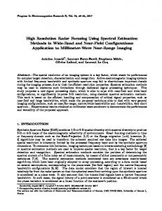
Figure 1. Scattering of microwave radiation from the human body results in reception of signals which have no foundation in the reradiating target (here a handgun) current, these signals then superpose the LTR of any concealed target objects making detection, location and identification of concealed threats very difficult. only usefully be used to give a few aspect independent CNR frequencies for object identification. The major problem that hampers the CNR approach to identifying concealed weapons upon the human body arises from the differential time delay in the reception of scattered signals from the body, see Figure 1. Here the paths, from the transmitter to the target’s head and −−→ back to the receiver, AB, and that from the transmitter to the target’s −−→ feet and back to the receiver, EF , are longer than the path from the −−→ transmitter to the concealed handgun and back to the receiver, CD. This results in any LTR being superposed and corrupted with the prompt or reflected returns from the more distant parts of the body; this makes the spatial localisation and identification of any threats concealed on the human body very difficult, if not impossible. This effect is clearly absent in the equivalent airborne target situation where the LTR of the airborne target is not degraded by reflections or ‘clutter’ from other objects that scatter radiation and then are received as overlapping the target LTR. Application to on body detection involves the target object(s) being located on, a much bigger, scattering structure (the human body), which does not have its own LTR as surface currents cannot flow for significant time after excitation, unlike a handgun where an LTR ∼ 10 ns is typical [14, 16]. The reception of
Progress In Electromagnetics Research, Vol. 124, 2012
191
these scattered signals, which do not have an origin in the induced surface currents that circulate on the metal object, simultaneously with the object’s LTR, gives a signal, which, although it contains aspect information of any concealed metallic targets, is dominated and obscured by the background term B in (1). The form of B is unpredictable as the body changes posture and orientation and human bodies are inherently of different shapes and sizes so this effect cannot be effectively removed by signal processing techniques. One possible way to minimize the background clutter term B in (1) is to spatially localize the transmitted illumination or the field of regard of the receiver. If a sufficiently small area of the body can be illuminated, then the scattered signal from the body and any concealed item within the localized area of illumination will consist of the immediate or prompt reflection of the incident pulse from both body and the concealed target (these prompt reflections will be received practically simultaneously if the path length to the receiver is large compared with the size of the interrogated area) and the LTR of the concealed item convolved in the time domain with the excitation pulse. Under these circumstances the LTR will no longer be corrupted by superposition with clutter and the aspect independent CNR frequencies may be successfully extracted from the LTR using the Generalized Pencil Of Function (GPOF) method [36– 41] to decompose the LTR into a set of complex residues and poles by solving a generalized eigenvalue problem. The complex residues are the amplitudes Cm and the poles are the CNR Zm from (1). In the case of a real valued time domain signal, CNR that correspond to physical resonances manifest as complex conjugate pairs whereas those CNR with no conjugate pairs are not physical and this fact is used to filter out spurious CNR. The CNR with αm < 0 can also be discarded, as they give rise to exponentially growing resonances which are also not physical solutions. The GPOF method is the most efficient way of decomposing signals of the form given in (1), providing the term B is Poisson noise [36], as would be expected for a target in an anechoic environment; however, since this is not the case for on body detection and B is certainly a non-Poisson “noise” source this means that the GPOF algorithm may not be optimal for this purpose. 2. PHASED ARRAY IMAGING Phased array technology, both for beam steering and for imaging applications [42] have been widely studied and reported in the literature. In the beam steering case each transmitter element comprising the phased array antenna is fed a phase shifted input signal
192
Harmer et al.
with respect to another transceiver element (equivalent in the time domain to time shifted). This is done according to a pre-calculated prescription (based on the range to the desired focusing plane, transmitter element separation and desired lateral focal position), so that at the desired point in the desired focal plane the emitted signals from all antennae comprising the array arrive coherently and so constructively interfere at that point. In this way an antenna, comprising an array of low gain elements, can give large gains and can be both electronically steered and focused. A similar but reciprocal methodology applies to utilizing a phased array of antennae for imaging (receiving). Here an array comprised of spatially separated, low gain receiving elements, is used to capture data over a time interval of interest. The temporal data from each receiving element is then time shifted (equivalent to a phase shift in frequency domain) such that all signals emitted from one lateral point on the desired image plane are coherent (this is equivalent to time shifting so that all signals from the desired point in the desired image plane arrive simultaneously in all receiver elements). The resulting shifted data from each receiver element is the summed to give the reconstructed image of the point in the image plane. In this way an image consisting of multiple points in the desired image plane can be reconstructed (this can be done retrospectively in software by applying the correct time shifts, or equivalent phase shifts, to each receiver element’s data). A brief mathematical description of the operation of phased antennae arrays for the purposes of beam steering and imaging is now presented. We represent the amplitude emitted by the transmitter pixel m, n at a time step k by, A0 [m, n, k], where the time step is defined as t = k∆t where ∆t is the time resolution (determined by the bandwidth of the illuminating pulse) and the spatial step is defined by x = m∆x and y = n∆x. Similarly the amplitude at the p, q pixel of the focal plane at time step l where t = l∆t is represented by A[p, q, l]. The relationship between the time steps l and k is simply, 1 k=l− (tdelay [m, n, pf , qf ] + ttof [m, n, p, q]) (3) ∆t where tdelay [m, n, pf , qf ] is the time delay (or equivalent phase shift) that needs to be introduced to the m, n transmitter element to steer the beam to the pixel pf , qf on the focal plane and ttof [m, n, p, q] is the time of flight for a pulse emitted from the m, n transmitter element to the p, q pixel on the focal plane. The relationship between the amplitude on the transmit A0 and focal planes A can be shown to be; X A0 [m, n, k] p A[p, q, l] = (4) 2 ∆x2 + (q − n)2 ∆x2 + z 2 (p − m) m,n
Progress In Electromagnetics Research, Vol. 124, 2012
193
Hence applying Equations (3) and (4) we have, £ ¤ X A0 m, n, l− 1 (tdelay [m, n, pf , qf ]+ttof [m, n, p, q]) p ∆t A[p, q, l] = (5) (p−m)2 ∆x2 +(q−n)2 ∆x2 +z 2 m,n The time of flight and required time delay can be shown to be satisfied by (6) and (7): 1p ttof [m, n, p, q] = (p − m)2 ∆x2 + (q − n)2 ∆x2 + z 2 (6) c q 1 tdelay [m, n, pf , qf ] = − (pf − m)2 ∆x2 + (qf − n)2 ∆x2 + z 2 (7) c In the case of phased array imaging the focal plane p, q is now the source of emission and appropriate delays are applied to the receivers m, n to image that point. The time delays applied to the received data to image coherently emission from the pixel given by pf , qf are: q 1 tdelay [m, n, pf , qf ] = − (m − pf )2 ∆x2 + (n − qf )2 ∆x2 + z 2 (8) c The time of flight is, as before, given by (6). Relating amplitudes on both planes, X A[p, q, l] p A0 [m, n, k] = (9) (p − m)2 ∆x2 + (q − n)2 ∆x2 + z 2 p,q where we now have the relationship between time steps 1 l=k− (tdelay [m, n, pf , qf ] + ttof [m, n, p, q]) ∆t and hence
(10)
A0 [m, n, k] £ ¤ X A p, q, k − 1 (tdelay [m, n, pf , qf ] + ttof [m, n, p, q]) ∆t p = (11) (p − m)2 ∆x2 + (q − n)2 ∆x2 + z 2 p,q To reconstruct the image all receiver channels are summed with appropriate shift and the resultant of that summation is the image pixel Aˆ [pf , qf , k] £ ¤ X A p, q, k − 1 (tdelay [m, n, pf , qf ] + ttof [m, n, p, q]) ∆t p = (12) (p − m)2 ∆x2 + (q − n)2 ∆x2 + z 2 m,n,p,q ˆ f , qf , k] denotes the reconstructed image of A[pf , qf , k]. where A[p
194
Harmer et al.
Although the above treatment is argued in the time domain, as the authors feel this approach is more intuitive, the proposed system uses SFCW to synthesize sharp pulses in the time domain [35] so the phased array focusing is carried out at each frequency step used in the SFCW system. In this case the time delays required for constructive interference are introduced as phase shifts in each of the frequency steps that are used for SFCW pulse synthesis. It should be noted that one obtains the same end results independently of whether the phased array focusing is carried out by means of time shifts or phase shifts. 3. NUMERICAL SIMULATIONS The equations presented were implemented in the commercially available mathematics package MATLAB to simulate the situation of illuminating a target (human and/or handgun) by a beam steered, phased array of UWB transmitter elements and subsequent imaging of the scattered signals by a nominally identical phased array of receiver elements. The illuminating beam is steered onto the central area of the human body, at waist level (see Figure 3) and imaging is achieved by reconstruction of a field of view sufficient to include the entire human body.
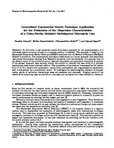
Figure 2. The geometry of the phased array system consists of two parallel planes separated by a distance z. The coordinates x0 , y 0 describe the phased array plane and the coordinates x, y describe the plane which the array is focused upon. When discretised these coordinates are replaced by the integers m, n and p, q respectively which label pixels.
Progress In Electromagnetics Research, Vol. 124, 2012
195
Figure 3. Two dimensional objects, defined at a spatial resolution of 10 cm, used to represent the human body (top left) and the concealed handgun (top right) in the MATLAB simulations. The gun is concealed centrally on the body at waist height. The body and the gun are run separately and the results summed, this is the reason for the gun shaped cavity on the human body. The corresponding microwave images from a 100 transceiver element phased array are shown below the body (bottom left) and gun (bottom right). The receiver array is co-aligned in the same plane as transmitter array; see Figure 2, although this configuration requires a transceiver capable of simultaneous transmission and reception with single antenna element. An alternative arrangement would be to have separate transmission and receiving arrays positioned adjacent to one another. Two sizes of phased array systems are simulated, the larger consisting of a square populated by 10 by 10 (100 in total) transceiver elements, and the smaller with 4 by 4 (16 in total) transceiver elements. The transceiver elements are arranged equidistantly and with phase centers separated by 50 cm (about the size of a single antenna). Results are also presented for a single transceiver where there is no focusing by a phased
196
Harmer et al.
Figure 4. The monocycle pulse that is assumed to be the transmitted time domain pulse as synthesized using SFCW. The time resolution is 0.2 ns corresponding to an antenna bandwidth of ∼ 5 GHz. array. The results from the transceiver array are defined at a spatial resolution of 10 cm. The UWB antenna used for each transceiver element is loosely based on a RC (Resistive Capacitance) loaded bow tie antenna proposed for ground penetrating radar work [43]. GPR (Ground Penetrating Radar) has similar antenna requirements to those needed for CNR based on body concealed weapon detection. This antenna can pass a monocycle pulse of width ∼ 1 ns, with minimal ringing (see Figure 4), which gives a good broadband emission over a frequency range of 0.3–5 GHz (encompassing the first several CNR of a typical handgun) [14]. Such a frequency response is essential for obtaining a clean LTR from any excited metal targets, since a sharp, well defined pulse in the time domain can be synthesized by using SFCW techniques and will result in minimal interference with the target LTR (2) Each antenna is also assumed to have, for simplicity, zero gain, so that it radiates isotropically and the temporal pulse passed is identical in all directions. Although antenna that work in the desired frequency range may have a reasonable gain (typically > 2 dBi), they need to be quite large for an appreciable directivity. The zero intrinsic gain assumption is not, therefore, an unreasonable approximation for small antenna. To include the non-zero intrinsic gain of each transceiver element the amplitudes in (14) and (21) would need appropriate scaling factors that depend, in general, on the direction of propagation and thus
Progress In Electromagnetics Research, Vol. 124, 2012
197
the synthesized temporal pulse passed would also be a function of propagation direction. The LTR for an automatic handgun (see Figure 5) was generated by using the first three CNR obtained from finite element modeling of such a weapon [14] using GPOF method [36–41] to decompose the numerically simulated LTR into a set of complex amplitudes and poles by solving a generalized eigenvalue problem. The amplitudes being used are for a typical orientation (side on, with a 45 degree barrel tilt with respect to the incident electric field polarisation), and performing a convolution of this time series data with the monopulse assumed emitted by the antenna. In this way the frequency characteristics of the antenna are included in the simulation and this is important as it found in practice that this is a key limitation of CNR recovery from LTR [14–16]. The effects of the antenna response have to be removed by deconvolution with the known response and is typically performed in the frequency domain and is a pre-requisite of finding accurate CNR. Without the deconvolution of the antenna response, the CNR are shifted and in the case where the antenna has its own late time resonances these dominate and mask the CNR of any concealed objects. The lateral spatial resolution of an active microwave imaging system operating in the frequency range required (for excitation of the fundamental CNR), even with such a large aperture as the one proposed, will be poor. The images so constructed will be of very coarse quality, such that even the broad outline of the human body will be uncertain; however this lack of detail is not important for the approximate isolation of any concealed metal items, since their associated LTR will show up in the temporal component of the image and the spatial location of the source of these LTR’s does not really need to be any more precise than the size of a human body upon which the object is concealed (∼ 1 metre). This will allow individual people to be screened by presence or indeed absence of LTR and any LTR traces tied to individuals, since the spatial localization of the sources of these LTR’s is easily sufficient for this purpose. The complex permittivity of water at 1 GHz ∼ 80 + i4.4 [44] is used to estimate the absolute reflectivity value of human tissue ∼ 0.80 and this value is used in this simulation. Metallic items are assumed to reflect all incident radiation, and thus have an absolute value of reflectivity of 1. 4. RESULTS The handgun and the human body simulations are run separately (see Figure 3) and the results are then superposed to simulate the case
198
Harmer et al.
Figure 5. The LTR of a nominal automatic handgun, obtained by temporal convolution of the monocycle pulse displayed in Figure 4 with the impulse response of a handgun with CNR: −0.345 + i0.449; −1.02 + i0.805; −0.872 + i1.87. The temporal extent of the LTR is clearly significantly longer than the temporal extent of the excitation pulse alone (compare with Figure 4). of a person carrying a concealed handgun. In these simulations the range to the target from the phased array antenna to the human body and/or gun is two metres, as this distance represents a reasonable range of operation for the envisaged use as a screening portal; at much longer ranges the beam size becomes too large to illuminate and image a localised part of the human body and the consequent temporal broadening degrades the quality of the LTR, as is discussed in Section 1. The synthesized temporal pulse is considerably shorter than the LTR excited from a typical handgun (see Figures 4 and 5) and thus the spatial location of any long lasting ringing may be located from the phased array image, and the strongest (largest amplitude) source may be reasonably presumed to be the location of the concealed metal item. To illustrate this, the phased array imagery data (simulated using the larger phased array) for the handgun alone was calculated (see Figure 6); the temporal data was found to have largest amplitude for the pixel coincident with the handgun’s location. As one moves away from the location of the handgun, the amplitude of the LTR decreases significantly; 30 cm (3 pixels) away from the handgun the amplitude has approximately halved and this value is halved again when one looks at temporal data from a pixel
Progress In Electromagnetics Research, Vol. 124, 2012
199
60 cm (6 pixels) from the location of the handgun; 90 cm (9 pixels) away the LTR is very much attenuated. It may be seen (see Figure 6) that in addition to a reduction in amplitude of the LTR, moving away from the location of the handgun results in degradation of the LTR; which in the case of the gun alone consists of time shifted, superposed copies of the LTR. From these results it is clearly possible to locate the object’s position to within ∼ 30 cm; furthermore because the LTR contains the aspect independent CNR frequencies of the object, it is possible to indentify the object as being, in this case, a handgun using the GPOF method, providing the CNR of the object are known a-priori. The identification of handguns that are not concealed on the human body, rather they are suspended in space, in an anechoic chamber is easily demonstrated in the laboratory [16]; the measured LTR of an air pistol is displayed in Figure 7. Contrasting the results of illumination of the handgun alone (see Figure 6) with illumination of the human body, without the concealed handgun (see Figure 8), clearly shows that there is no LTR ringing
Figure 6. Temporal plots of the imaged handgun at a range of 2 metres, off body, in anechoic environment. The illuminating beam is steered centrally onto the target by a phased array consisting of 100 (10 by 10) antenna elements. Each curve represents the time domain data for a reconstructed object pixel of spatial resolution 10 cm square. The LTR for the pixel which coincides with the position of the handgun (solid curve) is very similar to the LTR of the handgun (Figure 5.) as expected; whereas pixels which do not coincide with the weapon’s location have a smaller amplitude and are perturbed by clutter.
200
Harmer et al.
associated with the human alone and the temporal return from a person without a concealed handgun appears very different from that of the handgun alone. The human body simply reflects the transmitted monopulse so that the received temporal data looks very much like the transmitted monopulse for the central reconstructed object pixel; whereas pixels which do not coincide with the body have smaller amplitude and are perturbed by clutter, which in this case consists of time shifted, superposed monopulse reflections from all parts of the human body (see Figure 8). When the human body is simulated with a concealed handgun (concealed centrally at waist level) the reconstructed temporal data (see Figure 9) is clearly very different from that of the human body without the weapon. The LTR for the object pixel which coincides with the position of the handgun (solid curve in Figure 9) has a distinct LTR, however the shape is different to that of the gun alone (see Figure 6) and is very obviously different from the human body without the handgun (see Figure 8). Pixels which do not coincide with the weapon position have a smaller amplitude and are perturbed by clutter, which in the case of the gun on body, consist of time shifted, superposed LTR and monopulse reflections from the human body. Reducing the number of transceiver elements in the phased array results in a less tightly focused beam, both illuminating the scene and in imaging (sampling) the scene and this has a deleterious effect on the quality of the LTR obtained. The worsening of the LTR is due to the effect of time broadening by
Figure 7. The LTR of an air pistol measured using a single transmitter and single receiver in the laboratory inside an anechoic chamber.
Progress In Electromagnetics Research, Vol. 124, 2012
201
reflection of the transmitted pulses as has been discussed earlier. The ability to spatially localize the source of the LTR is also degraded, as would be expected, because of the wider beam. Figure 10 shows the ability of the smaller (16 transceiver elements) array to spatially localize the source of the LTR of the handgun concealed on the human body. Comparison of Figures 9 and 10 clearly show that the attenuation in amplitude of the LTR falls off less markedly, with offset from the handgun location, in the case of the smaller phased array than is the case with the larger array; thus spatial location of the source of the LTR is less accurate for the smaller array. Furthermore, the LTR ringing appears less pronounced in the case of the smaller array than is the case for the larger array; this is due to less effective
Figure 8. Temporal plots of the imaged human body, at a range of 2 metres, in an otherwise anechoic environment. The illuminating beam is steered centrally onto the body. Each curve represents the time domain data for a reconstructed object pixel of spatial resolution 10 cm square. The LTR for the pixel which coincides with the centre of the body (solid curve) appears very similar to the emitted monocycle pulse (see Figure 4), whereas pixels which do not coincide with the body have a smaller amplitude and are perturbed by clutter; which in the case the body alone consists of time shifted, superposed reflections, from all parts of the human body, of the monocycle pulse. The time offset on the temporal axis is due to time of flight from transmitter to target and back to receiver and the artificial time shifts introduced for focusing.
202
Harmer et al.
suppression of temporal broadening effects resulting from the larger beam width (coarser imaging) provided by the smaller array. A single antenna cannot determine the spatial location of the LTR and temporal broadening obliterates much of the LTR (see Figure 11) making a single antenna system for screening for concealed weapons very unlikely to work in all but the most contrived conditions. Processing of the temporal data, to remove the prompt response, i.e., the reflection of the monopulse and leave the LTR intact, enables the identification of the concealed object by application of the GPOF algorithm. This processing to extract any predominant LTR from the reconstructed temporal data can also be used to locate the spatial source of the LTR as was discussed earlier. The processing steps required to extract the LTR from phased array imaging of the illuminated scene to provide threat location and identification stage are summarized as follows: 1. Use SFCW radar, focused by phased array to illuminate target. Simultaneous phased array imaging of illuminated scene produces image of scene at all microwave frequency steps in the SFCW
Figure 9. Temporal plots of the reconstructed image of handgun on the human body, at a range of 2 metres, in an otherwise anechoic environment provided by the larger phased array (100 transceiver elements). The illuminating beam is steered centrally onto the target. Each curve represents the time domain data for a reconstructed object pixel, at a spatial resolution of 10 cm, which are located on the concealed handgun and then successively offset by 30 cm.
Progress In Electromagnetics Research, Vol. 124, 2012
2. 3.
4. 5.
203
regime used. Time domain transform of frequency domain data from step 1 to give time domain radar image by pulse synthesis [35]. Scan microwave phased array image in temporal domain to find spatial locations of pixels with significant LTR and store these locations. Separation of LTR from early time response (direct reflections) for all significant LTR present. Application of GPOF to data from step 4 to identify object by comparison with known library of threat CNR; store identities of threats and their positions in scene.
Using the GPOF method to extract the CNR by decomposing the LTR works very well for the cases where the LTR can be easily separated from the prompt response, as is the case for the handgun alone (see Figures 6 and 7); however where there is significant reflection from the human body, the separation of the LTR from the prompt response is more problematical. A simple method of LTR separation is realized by finding the maximum peak in the temporal data, which
Figure 10. Temporal plots of the reconstructed image of handgun on the human body, at a range of 2 metres, in an otherwise anechoic environment provided by the smaller phased array (16 transceiver elements). The illuminating beam is steered centrally onto the target. Each curve represents the time domain data for a reconstructed object pixel, at a spatial resolution of 10 cm, which are located on the concealed handgun and then successively offset by 30 cm.
204
Harmer et al.
Figure 11. Temporal plot of the handgun on the human body, at a range of 2 metres, in an otherwise anechoic environment provided by a single transceiver element. There is a great deal of corruption for several ns after the first pulse is reflected by the body, this corruption makes the decomposition of the LTR difficult. A very attenuated LTR “tail” is still observable but in practice this is very weak and is not easily separated from the temporal clutter. in most cases is associated with the prompt response, and, after a set time delay, sampling the data from a time window of preset length. The time delay is estimated from the width of the transmitted excitation pulse, which is ∼ 2 ns for the case simulated (see Figure 4); whereas the sampling window length is estimated by measurement of the time taken for the LTR to decay into the background noise clutter, about ∼ 10 ns, as is seen in the experimentally measured case of an airpistol (see Figure 7). Applying this delay and windowing technique to the temporal data with the most prominent LTR for the two arrays simulated and the single antenna case gives the LTR data shown in Figure 12. Again, it is clear that the larger array presents a cleaner appearance than the data from the smaller array and the single antenna case. The results of applying the GPOF algorithm to these LTR data are presented in Table 1; as expected the single antenna LTR data is so corrupted that the recovered CNR do not correlate with the CNR of the handgun; this is what happens in practice when one tries to isolate LTR from a handgun that is concealed on a person — the CNR obtained from the LTR data do not allow the identification of an item or the discrimination of items. This situation is slightly improved with
Progress In Electromagnetics Research, Vol. 124, 2012
205
Figure 12. The LTR data for the handgun on body after processing through steps 1–4. These LTR are then processed by the GPOF algorithm to give the aspect independent CNR frequencies which can be used to identify the object (see Table 1).
Table 1. Results of applying the GPOF algorithm to the LTR data obtained for the handgun concealed on body. The Model order was 10 and only CNR that occur in complex conjugate pairs and give rise to decaying oscillations are shown. The entries in bold type are associated with the CNR of the handgun, which are known to be: −0.345+i0.449, −1.02 + i0.805 and −0.872 + i1.87. Number of Tranceivers in Array 1
16
100
CNR Found
Relative Amplitudes
−0.0113 + i0.235 −2.01 + i0.465 −0.551 + i0.841 −0.105 + i1.02 −0.0097 + i0.202 −0.0455 + i0.453 −0.308 + i0.471 −0.397 + i0.954 −1.10 + i0.200 −0.359 + i0.447 −1.04 + i0.828
0.143 1.00 0.443 0.106 0.0637 0.602 1.00 0.234 1.00 0.783 0.184
206
Harmer et al.
the 16 transceiver array as the CNR picks out the fundamental CNR (−0.345 + i0.449) with tolerable accuracy, finding −0.308 + i0.471; however the 100 transceiver array does a better job and finds both the fundamental and a higher order CNR (−1.02 + i0.805) with better accuracy. In the case of the gun alone there is no problem in finding all three CNR with a single antenna, since the LTR is largely uncorrupted by reflected clutter. The optimum number of elements required to give a reasonably sized antenna array, which can reliably detect, identify and spatially locate concealed weapons, almost certainly lies in the region of 16–100 elements. This conclusion is easily drawn from the results presented: whereby single and sixteen element antenna arrays do not provide sufficient clarity of LTR; yet a one hundred element array certainly gives a good uncorrupted signal (see Figure 12). Since a square sixteen element array is about 2 metres square and a one hundred element array is 5 metres square it seems reasonable to assume that an actual system might well be forced, by size requirements alone, toward the lower number (16) of elements. 5. SUMMARY To identify concealed threat objects, of size commensurate with that of a handgun, by means of their LTR, requires a phased array of antennae. The increased directivity afforded by such an array gives sufficient beam localization at microwave frequencies, reducing the temporal clutter which degrades the LTR and prevents one acquiring accurate estimates of the concealed objects CNR. Further, the ability to reconstruct a microwave image, by means of phased array imaging, allows spatial localization of the threat objects present in the scene to an accuracy approaching the spatial resolution achievable with the array, ∼ λ/L radians. It is demonstrated that an array consisting of resistively loaded bow-tie antenna [43], of the kind developed for GPR work, and could be used to realize such a screening system. A phased array consisting of sixteen antennae would allow the determination of the fundamental CNR of a handgun concealed on the body; such an array would measure 2 metres square. A larger array consisting of 100 antennae would provide increased performance but would be impracticably large, measuring 5 metres square. The analysis presented considers only square configurations where the spacing of the antennae that make up the array is minimal; fewer elements might be used if a sparse array design [45] is utilized, saving on the number of antenna elements and transceiver channels required to implement an effective solution.
Progress In Electromagnetics Research, Vol. 124, 2012
207
REFERENCES 1. Appleby, R. and R. N. Anderton, “Millimeter-wave and submilimeter-wave imaging for security surveillance,” Proceedings of the IEEE, Vol. 95, No. 2, 1683–1690, Aug. 2007. 2. Oka, S., H. Togo, N. Kukutsu, and T. Nagatsuma, “Latest trends in millimeter-wave imaging technology,” Progress In Electromagnetic Research Letters, Vol. 1, 197–204, 2008. 3. Kemp, M. C., A. Glauser, and C. Baker, “Recent developments in people screening using terahertz technology — Seeing the world through terahertz eyes,” Proc. SPIE, Vol. 6212, 27–34, 2006. 4. Appleby, R. and H. B. Wallace, “Standoff detection of weapons and contraband in the 100 GHz to 1 THz region,” IEEE Trans. on Ant. and Prop., Vol. 55, No. 11, 2944–2956, Nov. 2007. 5. Federici, J. F., B. Schulkin, F. Huang, G. Dale, R. Barat, F. Oliveira, and D. Zimdars, “THz imaging and sensing for security applications — Explosives, weapons and drugs,” Semiconductor Sci. Tecnol., Vol. 20, No. 7, S266–S280, Jul. 2005. 6. Sheen, D., D. McMakin, and T. E. Hall, “Three-dimensional millimeter-wave imaging for concealed weapon detection,” IEEE Trans. MTT, Vol. 49, No. 9, 1581–1592, 2001. 7. Volkov, L. V., A. I. Voronko, N. L. Volkova, and A. R. Karapetyan, “Active MMW imaging technique for contraband detection,” 33rd European Microwave Conference, 531–534, 2003. 8. Clark, S. E., J. A. Lovberg, C. A. Martin, and V. Kolinko, “Passive millimeter-wave imaging for airborne and security applications,” Proc. SPIE, Vol. 5077, 16–21, 2003. 9. Goldsmith, P. F., C. T. Hsieh, G. R. Huguenin, J. Kapitzky, and E. L. Moore, “Focal plane imaging systems for millimetre wavelengths,” IEEE Trans. MTT, Vol. 41, No. 10, 1664–1675, Oct. 1993. 10. Zouaoui, R., R. Czarny, F. Diaz, A. Khy, and T. Lamarque, “Multi-sensor millimeter-wave system for hidden objects detection by collaborative screening,” Proc. SPIE, Vol. 8022, 802209, 2011. 11. Sheen, D. M., T. E. Hall, R. H. Severtsen, D. L. McMakin, B. K. Hatchell, and P. L. J. Valdez, “Standoff concealed weapon detection using a 350-GHz radar imaging system,” Proc. SPIE, Vol. 7670, 767008, 2010. 12. Sheen, D. M., D. L. McMakin, W. M. Lechelt, and J. W. Griffin, “Circularly polarized millimeter-wave imaging for personnel screening,” Proc. SPIE, Vol. 5789, 117–126, 2005.
208
Harmer et al.
13. Sheen, D. M., D. L. McMakin, T. E. Hall, and R. H. Severtsen, “Active millimeter-wave standoff and portal imaging techniques for personnel screening,” IEEE Conference on Technologies for Homeland Security, 440–447, 2009. 14. Harmer, S. W., D. A. Andrews, N. D. Rezgui, and N. J. Bowring, “Detection of handguns by their complex natural resonant frequencies,” IET Microw. Antennas Propag., Vol. 4, No. 9, 1182– 1190, Sep. 2010. 15. Hausner, J. and N. West, “Radar based concealed threat detector,” IEEE MTT-S Int. Microwave Symp., 765–768, 2007. 16. Harmer, S., D. Andrews, N. Bowring, N. Rezgui, and M. Southgate, “Ultra wide band detection of on body concealed weapons using the out of plane polarized late time response,” Proc. SPIE, Vol. 7485, 748505, 2009. 17. Rezgui, N., D. Andrews, N. Bowring, S. Harmer, and M. Southgate, “Standoff detection of concealed handguns,” Proc. SPIE, Vol. 6948, 69480L, 2008. 18. Andrews, D. A., S. E. Smith, N. Rezgui, N. J. Bowring, M. Southgate, and S. W. Harmer, “A swept millimetre-wave technique for the detection of concealed weapons and thin layers of dielectric material with or without fragmentation,” Proc. SPIE, Vol. 7309, 73090H, 2009. 19. Andrews, D. A., N. Rezgui, S. E. Smith, N. J. Bowring, M. Southgate, and J. G. Baker, “Detection of concealed explosives at stand-off distances using wide band swept millimetre wave,” Proc. SPIE, Vol. 711, 711719, 2008. 20. Andrews, D. A., N. J. Bowring, M. Southgate, E. Guest, S. W. Harmer, and A. Atiah, “A multifaceted active swept millimetre-wave approach to the detection of concealed weapons,” Proc. SPIE, Vol. 7117, 711706, 2008. 21. Bowring, N. J., J. G. Baker, N. Rezgui, M. Southgate, and J. F. Alder, “Active millimetre wave detection of concealed layesr of dielectric material,” Proc. SPIE, Vol. 6540, 65401M, 2007. 22. Yong, L., Y. T. Gui, N. Bowring, and N. Rezgui, “A microwave measurement system for metallic object detection using swept frequency radar,” Proc. SPIE, Vol. 7117, 71170K, 2008. 23. Novak, D., R. Waterhouse, and A. Farnham, “Millimeter-wave weapons detection system,” 34th Applied Imagery and Pattern Recognition Workshop, AIPR’05, 15–20, 2005. 24. Ibrahim, A. S., K. J. Ray Liu, D. Novak, and R. B. Waterhouse, “A subspace signal processing technique for concealed weapons
Progress In Electromagnetics Research, Vol. 124, 2012
25. 26.
27.
28. 29. 30. 31. 32.
33. 34.
35. 36.
209
detection,” Proceedings of IEEE International Conference on Acoustics, Speech and Signal Processing, Vol. 2, 401–404, 2007. Baum, C. E., “On the singularity expansion method for the solution of electromagnetic interaction problems,” Air Force Weapons Lab., Interaction Notes, Note 88, 1971. Wang, Y. and N. Shuley, “Complex resonant frequencies for the identification of simple objects in free space and lossy environments,” Progress In Electromagnetic Research, Vol. 27, 1– 18, 2000. Wang, Y., I. D. Longstaff, and C. J. Leat, “Measurement of complex natural resonances of targets in free space and lossy media,” Progress In Electromagnetic Research, Vol. 29, 221–230, 2000. Berni, A. J., “Target identification by natural resonant estimation,” IEEE Trans. Aerospace Electron. Syst., Vol. 11, No. 2, 147–154, 1975. Lee, J. H. and H. T. Kim, “Radar target discrimination using transient response reconstruction,” Journal of Electromagnetic Waves and Application, Vol. 19, No. 5, 655–669, 2005. Toribio, R., J. Saillard, and P. Pouliguen, “Identification of radar targets in resonance zone: E-pulse techniques,” Progress In Electromagnetic Research, Vol. 43, 39–58, 2003. Baum, C. E., “The singularity expansion method: Background and developments,” IEEE Antennas and Propagation Society Newsletter, 1986. Wang, Y., I. D. Longstaff, C. J. Leat, and N. V. Shuley, “Complex natural resonances of conducting planar objects buried in a dielectric half-space,” IEEE Trans. Geoscience Remote Sensing, Vol. 39, No. 6, 1183–1189, 2001. Lui, H. and N. V. Shuley, “Radar target identification using a banded E-pulse technique,” IEEE Trans. Antennas Propag., Vol. 54, No. 12, 3874–3881, 2006. Chauveau, J., N. de Beaucoudrey, and J. Saillard, “Characterization of perfectly conducting targets in resonance domain with their quality of resonance,” Progress In Electromagnetic Research, Vol. 74, 69–84, 2007. Robinson, L. A., W. B. Weir, and L. Young, “An RF time-domain reflectometer not in real time,” GMTT International Microwave Symposium Digest, Vol. 72, No. 1, 30–32, May 1972. Hua, Y. and T. K. Sarkar, “Generalized pencil-of-function method for extracting poles of an EM system from its transient response,”
210
37. 38. 39. 40.
41.
42. 43. 44. 45.
Harmer et al.
IEEE Trans. Antennas Propag., Vol. 37, No. 2, 229–234, 1989. Goswami, J. C. and A. E. Hoefel, “Algorithms for estimating instantaneous frequency,” Signal Processing, Vol. 84, No. 8, 1423– 1427, 2004. Hua, Y. and T. K. Sarkar, “A discussion of E-pulse method and Prony’s method for radar resonance retrieval from scattered field,” IEEE Trans. Antennas Propag., Vol. 37, No. 7, 944–946. 1989. Sarkar, T. K. and O. Pereira, “Using the matrix pencil method to estimate the parameters of a sum of complex exponentials,” IEEE Antennas and Propagation Magazine, Vol. 37, No. 1, 48–55, 1995. Lee, J. H. and H. T. Kim, “Natural frequency extraction using generalized pencil-of-function method and transient response reconstruction,” Progress In Electromagnetic Research C, Vol. 4, 65–84, 2008. Kitamura, M., J. Takada, and K. Araki, “A model order estimation in the matrix pencil method for the transient response of a microwave circuit discontinuity,” IEICE Trans. Electron., Vol. E82-C No. 11, 2081–2086, 1999. Fenn, A. J., D. H. Temme, W. P. Delaney, and W. E. Courtney, “The development of phased-array RADAR technology,” Lincoln Laboratory Journal, Vol. 12, No. 2, 2000. Lestari, A. A., A. G. Yarovoy, and L. P. Ligthart, “RC-loaded bow-tie antenna for improved pulse radiation,” IEEE Trans. Antennas Propag., Vol. 52, No. 10, 2555–2563, 2004. Kaatze, U., “Complex permittivity of water as a function of frequency and temperature,” J. Chem. Eng. Data, Vol. 34, No. 4, 371–374, 1989. Leahy, R. M. and B. D. Jeffs, “On the design of maximally sparse beamforming arrays,” IEEE TR. Anten. Prop., Vol. 39, 1178– 1187, 1991.