Abstract. The move to component-based development (CBD) is driven by a number of important requirements with respect to agile assembly of application ...
On Components and Objects: The Foundations of Component-Based Development Alan W. Brown and Keith Short Texas Instruments S o h a r e 6620 Chase Oaks Blvd , M / S 85 15 Plano, TX 75023, USA (a-w-brown, keiths)@ti.com
Abstract The move to component-based development (CBD) is driven by a number of important requirements with respect to agile assembly of application systems from pre-developed parts. However, to make CBD a reality requires a deeper understanding of the fundamental concepts of CBD and how those concepts can be embodied in tools and techniques. The most basic questions are in respect to what constitutes a component, how appropriate components can be found, and how to assemble components when building an application system. This paper addresses these questions and makes the case for more rigorous descriptions of comporreiit behaviors through the use of domain and specijcation models which allow interfaces and implementations of components to be more easily understood, analyzed, and combined.
1.
However, until recently existing approaches to CBD have tended to be ad hoc and uncontrolled, and, most importantly, have not been directly supported by established vendors of application development tools. For instance, finding components was not carried out in a systematic way, combining components involved large amounts of complex integration software, and the resultant systems are difficult to manage and upgrade to meet changing requirements or new operating environments [l]. Despite these problems there has been increased interest in CBD as a viable way to develop and maintain software, capturing the imagination of established software vendors. A wide variety of tools, techniques, process models, and applications now claim to be directly derived from a CBD approach (e.g., [14, 15, 16, 171). This has resulted in a lot of confusion about CBD, how these different approaches and technologies relate, and what is substantial and new about CBD as an approach to software development and maintenance.
Introduction
Recently there has been renewed interest in the notion of software development through the planned integration of pre-existing software component. This is most often called component-based developnrent (CBD), componentbased sojlware engineering (CBSE), or simply coniponentware. The interest in CBD is based on a long history of work in modular systems, structured design, and most recently in object-oriented systems. These were aimed at encouraging large systems to be developed, and maintained more easily using a “divide and conquer” approach. CBD extends these ideas, emphasizing the outsourcing of pieces of the application system, and focusing on controlled assembly of those pieces through well-defined interfaces. As a result, software development is achieved through a component selection, evaluation, and assembly processes where the components are acquired from a diverse set of sources, and used together with locally-developed software to construct a complete application.
0-8186-7940-9/97 $10.00 0 1997 IEEE
The basic thesis of this paper is that the c o a s i o n concerning CBD arises from two main sources. First, there is a lack of commonly agreed concepts and terminology with which to discuss CBD and the technologies which characterize it. Second, that while the abstract goals of CBD can be easily defined, there are a number of different starting points, assumptions, and specific goals for CBD which differentiate the CBD technologies under development. Rather than simply develop a glossary of CBD terminology (as attempted in [20]), the remainder of this paper addresses the two identified sources of confusion by exploring a number of fundamental questions with respect to CBD. The most basic questions are in respect to what constitutes a component, how appropriate components can be found, and how to assemble components when building an application system. This paper addresses these questions and makes the case for more rigorous descriptions of component behaviors 112
through the use of domain and specification models which allow interfaces and implementations of components to be more easily understood, analyzed, and combined.
components is required. At this stage little may be known about a component's characteristics. The information available may be simply its name, its parameters, and some idea of its required operating environment. Many of the component's required and available interactions with other components may remain hidden. This information about a component collectively provides the component's interface using a definition of interface that encompasses all potential interactions among components, not just an application programming interface [ 121. For developers of CBD tools, being able to describe the behavior of a component in a precise, rigorous way is an important goal, and will make component gathering less ad hoc and error prone.
The paper is organized as follows. Section 2 provides a description of the essential activities carried out by any CBD tool or technology, emphasizing the important role played in those activities by precise component descriptions. The subsequent three sections address key questions which follow from the description of CBD activities: What is a component? What is an interface? How is component behavior defined? Section 6 then discusses two interesting consequences of our analysis in the areas of tool support for CBD, and the relationship between components in CBD and objects in objectoriented systems. Section 7 concludes the paper with a summary of its main points.
2.
Qualified components have discovered interfaces so that possible sources of conflict and overlap among components have been identified. Discovery can take many forms, but usually involves detailed analysis of any available component documentation or specifications, discussions with component developers and users, and trial execution of the component in different settings. This is (by the definition of interface) a partial discovely; only those interfaces important to effective component assembly and evolution are identified. If more rigorous descriptions of component behavior are available, qualification activities can be reduced to validating that behavior through experimentationand trial use.
Essential CBD Activities
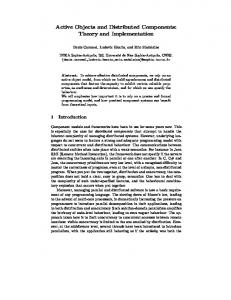
We begin by considering what tasks must be carried out in ay CBD approach. In particular, we identify the main activities which must be carried out to construct applications from sets of components, If the engineering of component-based systems can be considered primarily an assembly and integration process, then this suggests a simple framework [8] for describing the engineering activities involved in assembling component-based systems, as depicted in Figure 1. The vertical .partitions depicted in Figure 1 describe the central artifact of CBD, the components, in various states. Briefly stated, these partitions are as follows;
0
Gathered components consist of those identified as being of potential interest to an application developer. The components may come from a variety of local and remote sources, and hence a process of investigation into the properties and qualities of the Qualification to discover interface
-
Adaptation to remove architectural mismatch
__j
Adapted components have been amended to address potential sources of conflict among components which are to be assembled to form an application system. Typically, simple scripts are written as a buffer between user requests and component actions. The buffer can be used to provide default information to the components, eliminate access to unwanted component behavior, and act as an
Composition into a selected architectural style
Evolutionto update components
A A
n Off-the-shelf Components
Qualified Components
Adapted Components
Figure 1. CBD Activities. 113
Assem bled Components
Updated Components
insulation layer for the replacement of components. The figure implies a kind of component "wrapping," but other approaches are possible (e.g., the use of agents, intelligent mediators, and translators). Such approaches form a pallet of techniques for repairing the "architectural mismatch that is said to occur whenever integration of components from multiple sources is attempted [l, 121. In addition, the possibility then exists for providing "transformation wizards" which can translate between different component interfaces.
.
Assembled components have been integrated via some form of common infrastructure. For consistent component assembly the infrastructure must consist o i both a physical communication infrastructure such as a database or messaging infrastructure, and a set of conceptual agreements such as naming conventions that embody the shared semantics among the components. This infrastructure will support component assembly and coordination, and differentiates planned, coordinated component assembly from amalgamation using ad hoc "glue." A number of industry standards for component infrastructures have been developed to facilitate communication among different infrastructure implementations.
Many critical questions must be addressed with respect to component definition. However, three fundamental questions for any CBD technologies are: What is a component? What aspects of a component must. be defined to allow users to more easily gather, qualify, adapt, assemble, and upgrade components? How is component behavior defined so that it is easily and unambiguously understood? The rest of this paper explores these hndamental questions in some detail, describing the key aspects of components which make them essential to CBD technologies, introducing the notion of a component interface, and presenting an approach to defining component behavior which emphasizes rigorous description of the abstract behavior of a component.
3.
What is a Component?
The obvious starting point for any discussion of CBD is with the question of what constitutes a component. Currently, there is no agreements over what constitutes a component, nor how it differs from, say, a software module. However, there are a number of interesting elements which can be used to characterize components in various CBD technologies. Here we capture a broad understanding of components, drawing on ideas from many sources. Our exploration of what constitutes a component is based on emphasizing their principal distinguishing characteristics with respect to established software engineering techniques. We characterize a component as an independently deliverable set of reusable services. Hence, this characterization has two main elements, which we can examine independently. The first element is reusable services, which implies that a component provides capabilities that many other components may wish to access. To enable this, a fundamental tenet of CBD is that a component has a specification which describes what a component does, and how it behaves when its services are used. Given knowledge solely of the specification, any potential user,
Updated components have been replaced by newer versions, or by different components with similar behavior and interfaces. This aspect of component assembly must be expected and well-supported as an essential activity through appropriate definition of component interfaces and controlled interaction among components. Without careful planning, a change to one component can have extensive unforeseen repercussions on many other components in the system. With such planning the implications of component update can be reduced to at most selective re-writing of component wrappers, The 5 partitions of Figure 1 provide a useful framework for describing CBD activities. However, it is important to note that the framework's utility lies in the fact that no particular ordering or relationships are embedded within the framework. For example, it is not the case that the framework always be read from left to right as a process model for CBD. In reality, organizations employing CBD do so using a variety of different approaches. The value of this framework is that it provides a set of common terminology and concepts for describing these different styles of CBD. As can be seen from this framework for CBD, the way in which a component is defined is key to many of the activities which take place using any CBD technology.
or client, of those services can focus on its part of the
overall solution without concern for how those services are actually rendered. Useful components exhibit varying degrees of completeness and precision in their specifications, but any CBD approach must offer guidance on how to use the component specification to greatest effect. The services will be rendered by some programmer or designer who provides an implementation for a
114
component, expressed in terms of code and data which will be guaranteed to meet the specification. In general, the implementation may be written in a different programming language or execute on a different technology platform from the language and platform used by the client program. One component may be replaced by another in an application, as long as both purport to implement the same specification. The split between specijcation and implementation is the key to efjctive encapsulation, as illustrated in Figure 2.
4.
What is an Interface?
A component specification often includes a set of services which naturally group into meaningful clusters. These clusters of service specifications are known as interfaces. An interface summarizes how a client should interact with a component, but still hides underlying implementation details. It provides all the information a client can depend on, permitting the designer of the client to be unaware of any implementation, unaware potentially whether an implementation even yet exists.
In fact, although we’ve described interfaces from the point of view of component specifications, an interface may exist separately from any component which implements it. This is because an interface succinctly summarizes a parcel of behavior and responsibilities for some situation - behavior and responsibilities any component in that situation will have to uphold.
I
As a simple example, suppose a useful parcel of behavior is defined concerning the management of a set of names and addresses. This is defined by operations such as “add a new address” for a person, “how long” has a person been at an address, and “where” was a person living 3 years ago. Let’s call this bundle of behavior the interface ISimpleAddressManagement. Furthermore, suppose two software companies, Xsoft and Ysoft, separately decide to build components which offer address management capabilities for sale to application builders, so each has an implementation of ISimpleAddressManagement. Meanwhile, an application builder writing a personal information management application realizes that she needs address management capabilities. Scanning a catalog of interfaces, she finds one that looks right and by writing her code in terms of the ISimpleAddressManagement interface finds she has a choice of whether to buy from Xsoft or Ysofi. She decides to buy from Ysoft because it is cheaper.
Figure 2. Specifications and Independent
Delivery of Components,
The other important element of our definition of a component is independent delivery. This refers to the issue of context awareness of components. Independently deliverable components are typically unaware of the contexts in which they may be used. This stresses the notion that components are expected to collaborate with one another to accomplish a solution, not interfere with one another. In particular, components cannot be developed with embedded dependencies on one another, or on a shared external resource being present. One consequence of this, for example, is that two software components cannot share a common data structure directly. For example, two or more software components could not access the same columns is a relational database table. They may do so if, say, a third component took the responsibility for updating the same column, unbeknown to the first two components. This does not mean that components have no dependencies on one another. For example, a spell checking component may require the services of a dictionary manager component. Both components are always needed, but perhaps an appropriate dictionary manager can be acquired from several sources, and delivered independently. The solution to this lies in the creation of appropriate component interfaces.
But another application builder who is building a customer information system for a client also realizes that he needs an address management capability. Looking in an interface catalog, he finds ISimpleAdddressManagement and has the choice of discussing purchase from Xsoft or Ysoft. He notices that although Xsoft’s address management component is more expensive that that from Ysoft, it also supports IAdvancedAddressManagement. On consulting the interface definition lie finds that this would suit some other aspect of his application so decides to buy from Xsofi instead, This example is illustrated in Figure 3.
115
performance and availability data for typical execution of the component. However, to improve our ability to find components and to assemble them into application systems, more detailed and rigorous descriptions of component behavior are necessary. In this section we consider the elements of a component description which would facilitate more rigorous approaches to selection, comparison, and analysis of components. 5.1 Models
Figure 3. Using Different Implementations of Address Management.
This simple example illustrates a number of important points with respect to CBD. First, interfaces are the primary means for potential clients of a component to make decisions on whether a particular component is suitable. Hence, interfaces must be precisely and unambiguously defined, be easy to search, and be stored in some readily accessible form. Second, a component may offer multiple interfaces. Clients of a component may make use of one or more of these interfaces as appropriate. Third, well-defined interfaces encourage competition among component implementers, allowing potential users of a component to choose among them on the basis of non-functional attributes such as cost, quality of service, reliability, and so on.
5.
Both the implementation and specification of a component may be described in more helpful, abstract forms in terms of models of what they do. It is more usual for implementations to be described in terms of models. This has been the strength of CASE tools for the past decade. Often source code and other design artifacts are partially, and occasionally completely, generated from the abstract, easier-to-understand implementation models. But great value exists in having models of specifications too. Most efforts to describe specifcations take the form of interface descriptions in source code or text form. However, models of these which enable higher level abstraction are also possible. Advantages of doing this include: models of interfaces supply semantics of behavior: interfaces with models are easier to inspect to see whether they might be useful behavior bundles; components whose interfaces information can be self-describing;
How is a Component’s Behavior Defined?
From our definition of a component the importance of describing component behavior in some meaningful way is seen to be essential. To do this, both the implementation and the specification may be described in some source code or text The usual form of component behavior description may Consist of some or all of the follo+ng;
a list of operation names and signatures defining the input and output parameters for each operation;
an informal textual description of the component’s functionality, intended usage scenarios, and history of development; an informal description of the component’s operating context (e.g., hardware platforms and operating system), expected versions of installed software, and known limitations or deficiencies;
have
model
the impact of using someone else’s interface is easier to gauge if that interface has a semantic model. From this discussion we see that two particular kinds of models are of critical interest: domain models and specification models. A domain model represents objects within the domain of interest? and the relationships among them. A domain model sets the context for what applications will be trying to accomplish. Its focus may vary considerably, For example, it may be a business process, either one that exists, or a desirable target (e.g., an order fulfillment process for a large organization). In such cases the domain model might also include process models, workflow models, and details of collaborations in the process. It could be a small, complex part of one process (e.g., to gain a detailed understanding of the rules for credit checking during order fulfillment), or it could be some part of an engineering application (e.g., the objects
116
in the domain of a just-in-time stock control system wluch interact with the order fulfillment process). A specification model is a detailed description of a set of objects or an interface which completely specifies the behavior of that set, or that interface, in all possible circumstances of relevance to the domain. Note that in this context the notion of a “set of objects” is an important one. It allows collections of objects with similar behavior to be modeled by a single object type, more often abbreviated to type. Types are the essence of detailed object modeling. In essence the type of an object provides a boilerplate with which to describe individual objects. The external view of the type is the set of operations and the signatures (i.e., the parameters to the operations) the type is prepared to make available. The way an object’s state is modeled is also defined by the type. But implementation details of the operations or ways in which the state can be implemented are not part of the definition of the type. The type only provides a specification of the object’s behavior it is independent of any possible implementation.
-
If the operation signatures are said to describe what will happen when an operation supported by an object is called, then the specification model provides the explanation of what the operations mean - the semantics of interaction. These semantics must be precise and unambiguous to enable correct service selection, yet sufficiently rigorous to ensure precise and predictable outcomes during interaction. In particular, as all clients of a component rely on the interface definition, it is important that the behavior of the object over time is also defined. Figure 4 illustrates the central questions which underlie the relationship between domain and specification models. These questions are essential in supporting the search, assembly, and upgrade approach of CBD. Of course, in practice, both domain and specification models are comprised of several different kinds of diagrams which view aspects of the domains and specifications from different perspectives. Whichever notations are used a number of issues should be noted: Useful interfaces are built by understanding what behavior is required by individual objects which participate in key activities in the domain. Object types and collaborations are used to describe consistent behavior within the domain. Common, reusable behavior to be implemented by one or more components can be published as interfaces.
allowing greater chance of finding a close match than by simply browsing application programming interfaces (APIs). When an interface is used in a domain model, an accurate mapping can take place between the terms in the interface specification model and those in the domain model. The protocol for interacting with the interface can be specified in the domain model more precisely.
I
Figure 4. The Central Questions of Object Modeling for CBD.
5.2 Collaborations and Roles A component specification is responsible for describing the behavior of a component during all its interactions, As well as interactions among components, interactions among objects in the domain must also be examined. A type specification must capture the semantics of all possible interactions with it. A description of an interaction is called a collaboration. Collaborations may be complex, involving many parties and an agreed sequence of actions among them. During this sequence the same participant may play different roles, and at times different participants may play the same role. The role a type plays in a domain model collaboration can help select those aspects of behavior in a model which must be supported in an application system. Hence, interfaces are those roles and types for which we expect there to be an implementation.During application and component design, an interface will represent the role a component plays in an application model collaboration. This provides the important link between behaviar driven 6bjeCt modeling, and application design from componeents.
As an illustration, consider an example [ 181 from real life. Moving house is an example of a collaboration in which various parties are involved - realtors, attorneys, banks, local authorities, and individuals. Individuals often have two roles, as both vendor and purchasers. Various actions must take place in sequence, such as
Specification models of interfaces which have already been defined, and perhaps which have component implementations,can be matched against objects and collaborations in the domain model, 117
having the property surveyed before a loan can be secured. There are even actions which must take place simultaneously, such as exchanging contracts. As well as playing different roles in a collaboration, such as an individual property owner also being a vendor and purchaser, different participants may play the same role (e.g., there may be multiple vendors and purchasers in a chain of property transactions enacted simultaneously). Figure 5 shows a model of the Move House collaboration. It shows the objects and the roles they are playing, and shows that knowledge of an object is built up by accumulating the responsibilities they take on as participants in different collaborations. However, at this point the collaboration is not sufkiently detailed to understand clearly the responsibilities of all the participants. For example, if our task was to construct an information system to support the activities involved in moving house, we do not yet have sufficient detail to describe the interfaces required, and thereby to describe the software components to be reused or built.
The collaborations are further refined to describe more clearly the actions of which it is comprised, as shown in the lower half of Figure 5. The refinement indicates which of the participants are now involved in
Collaboration: M o v e H o u s e
the lower level actions, and whether these actions should be carried out sequentially, in parallel, or are conditional on some event. The diagram shows, for example, that the joint action ArrangeFinance involves participants aBank, aSurveyor, and thePurchaser. In practice, further refinements would be needed to be able to ascribe individual actions to the roles responsible for them. This results in a protocol involving localized actions for the roles, and describes the actions, their sequence, and their dependencies on actions of others in the collaboration. The actions may then be grouped into interfaces which provide a set of actions we want to name as a separate entity. A good way to help refine collaborations clown to the protocol between localized actions is using scenarios. A scenario is an example of the collaboration taking place, showing how the individual participants work together to achieve the objective of the collaboration. Scenarios therefore involve typical objects, not types, and are a good way of checking who does what in a collaboration. By using a variety of scenarios, most or all aspects of a collaboration can be examined, illustrating behavior in typical and unusual situations.
Sometimes collaboration descriptions are called use cases, especially when describing key events and actions
1-
Colla bora tion: Build Extension T W Oroles of s a m e type7
Vendor
3
9-
...
m
I Loan Provider I
h
‘y,
R erines
ICollaboration: M o v e H o u s e frefined, i n t b m p l e t e l l
I
I ~~
F i g u r e 5 . C o l l a b o r a t i o n s a r e R e f i n e d to I d e n t i f y R o l e s a n d L o c a l A c t i o n s .
118
___
in high-level business processes. Expressing these highlevel processes and interactions with customers using scenario analysis is then referred to as use case modeling. Many object modeling methods endorse use case modeling, but often fail to emphasize the significance of collaboration refinement, protocols, interfaces, and localized actions. As discussed, these are critical elements of behavior driven models. 5.3 Summary
Object modeling is critical to the definition of component behavior in CBD. The essential points involved in defining component behavior can be summarized as: Establish what important objects there are in the domain, and what important interactions occur between them.
Ramde Caponen!
Slae
I
Pallet
Workbench
Operatlonal System
Figure 6. Essential CBD Tool Elements.
As shown in Figure 6, there are three essential elements of a CBD tool: Pallet. A pallet is a repository of components of interest to a user. Analogous to a folder or directory in a file system, the components referenced by a pallet may share some characteristics relevant to the task at hand (e.g., they may be all visual components for user interface construction). The pallet may contain copies of the components, but more likely will contain component specification and interface descriptions. In either case the components may have been gathered from a variety of local and external locations, may be of different types, or in different formats. The primary role of the pallet is to provide some way to browse, search and index the available components based on their interface descriptions and specifications.
Do this by studying collaborations, a context for understanding detailed interactions among objects playing different roles. Specify context-dependentbehavior shared by many objects as a role, and general behavior as a type. Types and roles, being such similar concepts are usually shown using the same notation. Selected roles and types considered important for implementation of behavior are refined, grouped, and published as interfaces. The interfaces may then be enrolled in interface catalogs. In building applications, interfaces are allocated lo components, and the necessary implementations are acquired or developed from scratch.
6.
Lml Caponen!
Workbench. Certain components from a pallet will be selected and used collectively to build a system. The workbench facilitates this assembly process allowing the components to be imported from the pallet, modified or used as is, and for new components to be developed. In most cases the workbench will be configured to support rapid application development (RAD) so that components can quickly be assembled, tested, and modified. To facilitate this RAD style the workbench may be specialized for a particular application domain. For example, the workbench may be specifically used to create graphical user interfaces. As a result, the workbench may include processes, frameworks, or components specific to that domain. In such cases, domain knowledge may be embedded within “wizards” which guide the user through component selection and assembly scenarios, making integration easier and more robust.
Observations
While an understanding of component identity, specification, and behavioral modeling is important to many aspects of CBD, two particularly interesting areas for observations are worthy of note. The first concerns the role of component identity in any CBD tool. The second is the relationship between component identity in CBD and object identity in object-oriented programming languages and systems. 6.1 Elements of a CBD Tool
Supporting the CBD process with automated tools requires a number of specific elements. These elements have a strong and obvious mapping to the activities identified in Figure 1. However, separating this operational view of CBD is useful because it highlights the tasks performed by any CBD tool, and can act as an illustrative high-level architecture for that class of tools.
Operational system. The applications must be deployed in some real setting. A CBD tool may include services to allow applications to be
119
partitioned among a set of processors, for remote monitoring and tuning of an application, or for online upgrade of components. While current tools provide relatively simple facilities in this regard, a number of approaches are being researched that will greatly improve on-line maintenance and upgrade of component-based systems [ 131.
The same terms can be applied to reusable pieces of design and requirements models. If models of classes and components are provided in a form which is extensible, then these are white-box model elements. Conversely for black-box model elements which must be used as is. Most people who are familiar with object-oriented programming systems (OOPS) are also familiar with using white-box classes - classes described as programming language source code, like Java or C++, which are made available to the OOPS. These are extensible using class inheritance which coupled with polymorphic behavior, enables high degrees of code reuse.
6.2 Components and Objects
A major challenge in understanding component-based development is to establish its relationship to better known object-oriented development approaches. For some people object oriented development has been around for 2 decades and has failed to capture the attention of corporate developers. It is often viewed as too hard to do, supported by too few tools, and requires staff who must be at least Computer Science graduates. Moreover, software reuse, the great Holy Grail of software has failed to substantially materialize. Many users of object-oriented languages and tools find themselves yet again locked in to another generation of legacy application technology. These people are looking to some new generation of object techniques, more pragmatic, and more tuned to providing realistic definition and reuse of components.
But typically, OOPS provide some way to package together a group of classes for use or reuse by others without the need to provide source code. These package concepts, a black-box mechanism for distributing object oriented code, provide some way to describe the methods in the package which may be called by a user. These are often termed the public methods of the package. Such a description bears a remarkable similarity to an encapsulated software component.
For others, CBD and object-orientation are synonymous. Components are simply classes, and provided object-oriented methods are used in modeling, and object-oriented programming languages are used for implementation, the promise of object-orientation (including large scale reuse) will eventually happen. The key is in deciding how to reward designers and programmers to encourage reuse, and provide them with the increasingly available class libraries and frameworks. Some key points concerning CBD and object modeling can be drawn from considerations such as these. Firstly, there is much confusion in the software industry concerning terms like object, class and component. The term interface, used extensively in component-based methods, gets scarcely a mention in the current generation of object methods. Are components the same as classes? Is a component the same as an interface? The next point concerns the importance of component extension and customization. If a potential user of a predefined executable class or component has access to its source code, then it is said to be a white-box component or class, since this implies some degree of extension is possible within the source code. If a component or class is offered without its source code, it may only be used as is, and is therefore described as a black-box component or class.
120
So is there a difference between a packaged set of classes and a black-box component? If not, does it actually matter whether the code inside the package bounday is itself object oriented provided the public methods are well-defined? We believe the answer is "No". Object modeling does offer some significant advantages, but it is entirely possible to have an object oriented model of the domain, with an object oriented component architecture, but with individual component implementationsin non-object oriented technology. This may be, for example, the only option for exploiting a worthwhile chunk of functionality from an old, legacy application. Many OOPS can be linked to tools which provide diagramming support for object analysis and design methods. Often it is possible to derive or generate some or all of the class definitions and method descriptions from the models. But in most cases, these methods and tools have no notions with which to describe the packages of classes. Yet as argued in this paper, a blackbox component which has a model of the methods or services it provides is a great deal easier to use than one which does not. How modeling tools and methods need to change in order to model component concepts is a key issue being addressed by a number of current vendors of object modeling methods and tools [ 191. An understanding of the basic concepts of modern object modeling methods is vital for addressing these questions. Such an understanding provides the
appropriate language to discuss how component-based applications are deployed, and how components may be brought to market.
7.
Summary and Conclusions
Component-based development of software is an important development approach for software systems which must be rapidly assembled, take advantage of the latest web-based technologies, and be amenable to change as the both the technology and application needs evolve. One of the key challenges facing software engineers is to make CBD an efficient and effective practice which does not succumb to the shortcomings of previous reuse-based efforts of the 1970s and 1980s. A first step on the road to a practical CBD approach is a consistent set of concepts and terminology. This paper has begun this process by identifying 3 fundamental questions of CBD, and discussing their important elements. While much further work remains to complete our understanding of CBD and its critical elements, we believe that a number of fimdamental aspects are clear. First, components must be described using models which describe the services the component makes available at its interfaces. Second, the models must be sufficiently rigorous to capture the semantics of the component's behavior in precise and unambiguous ways. Third, tools must be available to take advantage of these models as the basis for more accurate and intuitive component selection, assembly, and upgrade.
Texas Instruments Software is pursuing CBD as a major focus for future enterprise application development. By focusing on these three fundamental aspects, we believe that the Texas Instruments Software products will be in a strong position to take a leadership role in the CBD community.
Acknowledgments Texas Instruments Software has been working closely with Icon Computing Inc. on the development of a methodology for CBD. This paper draws on this collaboration, and owes a debt of gratitude to the work of Icon in developing the Catalysis method. For further information on Catalysis see http://www.iconcomp.com. Section 2 is based on ideas originally developed with Kurt Wallnau at the Software Engineering Institute.
References 1. D. Garlan, R. Allen, and J. Ockerbloom, "Architectural
Mismatch: Why its Hard to Build Systems Out of Existing Parts", Proc. of the International Conference on Software Engineering,April 1995. 2. D. Pamas, "Onthe Criteria for Decomposing Systems into Modules", CACM V15 #12, pp1053-1058, December 1972. 3. Numerical Algorithms Group (NAG) library of Mathematical Software, http://www.nag.co.uk. 4. R. Ofali, D. Harkey, J. Edwards, "The Essential Distributed Object Swvival Guide", John Wiley Press, 1996 5. OMG, "The Common Object Request Broker Architecture (CORBA)", Object Management Group, Framingham, MA, 1995, http://www.omg.org. 6. Microsoft, "Distributed Component Object Model Protocol DCOMfl.0 Specification" May 1996, http://www,microsoft.com/oledev/olecom/dcomsepc. txt. 7. D. Kara, "ComponentsDefined", Application Development Trends, June 1996.Available also at http://spgnet.com/ADT/june96/fe603too.html. 8. A.W. Brown and K.C. Wallnau, "Engineeringof Component-BasedSystems",Proceedings of the 2nd IEEE International Conference on Complex Computer Systems, October 1996. 9. E. Gamma et al., "Design Patterns: Elements of ObjectOriented Software", Addison-Wesley Press, 1995. 10 Microsoft, "MicrosoftVisual Basic 4.0: A Programming System for Windows Platforms", http://www.microsoft.com/vbasic/docs/visual 1.htm. 11 D. Parnas, "On the Design and Development of Program Families", IEEE Transactions on SoftwareEngineering V2 # 1, March 1976. 12. K.C. Wallnau et al., "Correcting,Identifying, and Avoiding Interface Mismatch: Theory and Practice", Submitted for publication, Software Engineering Institute, Pittsburgh, PA, August 1996. 13. L. Sha, R. Rajkuniar, and M. Gagliardi, "Evolving Dependable Real-Time Systems",Proceedings of the IEEE Aerospace Applications Conference, February 1996. 14. Elements 2, http://www.neurondata.com/products/ee:!.htm. 15, ClassIQ, http://www.metex.com/toolup.html. 16. Centura Team Developer, http://www.centurasoft.com/ products/papers/wp-ov/y-ov. htm. 17. TI Composer,http://www.ti,condsoftware/cbd.htm. 18. J. Cheesman, "The Semantics of Component InterOperation", Texas Instruments Tech. Journal, April 1997. 19. The Unified Modeling Language, Version 1.O, http://www.rational.com/ot/uml/1.Otindex.html. 20. ComponentwareGlossary, http://www.objs.com/survey/ ComponentwareGlossary.htm,1996.
121