Using the four modeling objects, following workflow mod- ... The activities within functional business areas are either manual, automated, ... ports, emails, etc.
ON CORRECTNESS ISSUES IN CONCEPTUAL MODELING OF WORKFLOWS∗ Wasim Sadiq Maria E. Orlowska CRC for Distributed Systems Technology School of Information Technology The University of Queensland Qld 4072, Australia Email: {wasim,maria}@cs.uq.edu.au ABSTRACT The conceptual modeling of workflows is the first, and arguably the most important, step towards understanding business processes. A well-defined workflow conceptual model leads to the development of an effective and reliable workflow application. This paper presents a graphical modeling technique for workflows. We introduce four graphical modeling objects: task, condition, synchronizer, and flow. Using the four modeling objects, following workflow modeling constructs are identified: ordering, alternative, exclusive join, concurrency, synchronization, iteration, start/stop, nesting, and contingency. It is possible to easily get into error situations while building large workflow specifications. We present a set of constraints for ensuring the correctness of workflow specifications. The concepts introduced in this paper are applied as a foundation to the development of a CASE tool for the modeling and syntactical verification of workflow graphs.
INTRODUCTION In today’s business environments, computers are extensively used for automating the business processes. The organizations are partitioned into several functional areas and information systems are developed for each of the divided areas. It is essential to understand the operations of business processes before any information systems are developed and implemented. For this purpose, business data and process modeling methodologies are applied. The activities within functional business areas are either manual, automated, or a combination of both. For big organizations, the systems supporting the functional areas run in heterogeneous and distributed hardware and software ∗
The work reported in this paper has been funded in part by the Cooperative Research Centres Program through the Department of the Prime Minister and Cabinet of the Commonwealth Government of Australia.
platforms. These systems communicate and coordinate with each other to achieve their functional objectives. The coordination of these automated or manual activities has historically been performed manually. In recent years, the possibility of automating the coordination of these different processing activities has been explored and called workflows. The workflows represent the organizational flow of information from one processing entity, either manual or automated, to another. The processing entities use this information to accomplish assigned tasks. These tasks take some information from the preceding tasks, perform some work based on the information received using the services of the assigned processing entities, and proceed to the next tasks in the workflow. The workflow management systems partially or fully take over the responsibility for coordinated execution of tasks from human coordinators. The execution coordination of tasks and processing entities is accomplished by enforcing procedural rules. In literature, there is no clear cut classification of workflows. The trade press classifies workflows into three categories: ad-hoc, administrative, and production on the basis of repetitiveness, predictability, control, and functionality requirements of tasks and workflows. Another classification is made on the basis of the processing entities: system-oriented and human-oriented (Georgakopoulos et al 1995). The ad-hoc workflows do not have a very well defined pattern for moving information from one processing entity to another. The ad-hoc workflow management systems typically require extensive human coordination for their operations. The execution path may be different for different workflow instances and is defined at the time a workflow is performed. The administrative workflows are similar in nature to the ad-hoc workflows except that the workflow execution is repetitive and predictable and it follows a well-defined execution path. Both ad-hoc and administrative workflows are usually not mission critical and do not interact with the organizational information processing systems. The primary use of such workflow management systems is to coordinate the flow of office information among people as documents, reports, emails, etc. The production workflows involve the coordination of organizational information processing systems that are usually based on database management systems. These workflows have well-defined procedures for the repetitive coordination of business activities and may span over several heterogeneous information systems of the organization. The production workflow management systems are more complex than ad hoc and administrative workflow management systems. They must have extensive features to define the internal task structures, control the execution of tasks involving different types of processing entities and support reliable failure recovery. The transactional workflows fall under the definition of production workflows. The concept of transactional workflows has been an active area of workflow research for the past few years (Rusinkiewicz & Sheth 1994; Hornick & Sheth 1995; Kuo et al 1996). The transactional workflows extend the basic 2
workflow model by introducing well-tested transactional features of the transaction management systems. The Workflow Management Coalition was founded in 1993 with the mission to promote the use of workflows through the establishment of standards for workflow technology. The coalition has proposed a reference model for the development of workflow management systems (Workflow Management Coalition 1996). The reference model assembles the generic components of workflow systems into six groups. One of the groups contains process definition tools that may be used to analyze, model, and describe business processes. The work presented in this paper defines a set of workflow modeling objects and constructs that conform to the specifications of process definition tools group of the workflow reference model. Before a workflow management system can be used to manage workflows, we apply process definition tools and techniques to model the workflow processes. This modeling information about the procedural rules is stored in a workflow repository. The workflow management systems make extensive use of this workflow repository in their operation. On the basis of the stored process definitions in the repository, workflow management systems create and execute the workflow instances and coordinate the interactions among the tasks within the workflow instance.
CONCEPTUAL MODELING OF WORKFLOWS The objective of a conceptual workflow model is to produce high-level specifications of the workflows independent of the workflow management software. A few workflow modeling techniques have been proposed and reviewed in the literature targeting specific workflow aspects (Rusinkiewicz & Sheth 1994; Casati et al 1995; Georgakopoulos et al 1995; Kuo et al 1996; Rajapakse & Orlowska 1995; Kamath & Ramamritham 1995). We are working on a generic workflow modeling methodology for process definition that should be applicable to all kinds of workflow applications (Sadiq & Orlowska 1996). The methodology, when completely defined, should cover several important aspects of workflow applications. The primary objective of a workflow management system is to coordinate the activities or tasks of an organization. Correspondingly, a workflow modeling methodology should cover the techniques and tools to capture, analyze, and specify the following different aspects of tasks and their coordination: • graphical modeling objects and constructs; • task characteristics and properties; • task structures; • data exchange properties among tasks; • inter task dependencies; • task execution and scheduling constraints; • task failure and recovery management; • exception management; 3
• • • •
criteria for assigning tasks to processing entities; correctness and reliability verification; evolution management; repository specifications. The workflow specifications may vary for different application areas. For example, we may not want to capture the task failure and recovery management properties for ad hoc workflows. The motivation of the work presented in this paper is to specify a framework for the development of a CASE tool for the workflow modeling. We introduce the conceptual workflow modeling objects and constructs of our proposed methodology and their graphical representation. We also present a set of constraints to verify the syntactical correctness of the graphical workflow specifications. The specifications of these two important aspects of workflow modeling are essential to develop a CASE tool for the modeling and syntactical verification of workflow graphs.
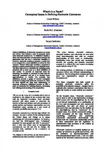
MODELING OBJECTS Most of the information modeling techniques include graphical representation that enhances the understanding of the model. A workflow specification could also be represented using graphical objects. The workflow specifications model proposed in this paper includes four types of objects: task, condition, synchronizer, and flow. The flows are used to link the first three types of objects together to build workflow specifications. Figure 1 shows the graphical representation of these objects in our model.
Figure 1. Workflow modeling objects Task A task represents the work to be done to achieve some given objectives. It is the primary object in workflow specifications and could represent both automated or manual activities. Tasks are performed by assigned processing entities. The workflow specifications place less emphasis on the internal workings of tasks. Their aim is to capture the coordination requirements for performing a set of tasks for a given business process. They do, however, capture some information about the execution of tasks that are needed for coordination. This information is represented by a set of externally visible states of task execution. All other modeling objects except the task are internal to the workflow management system and are used to specify the rules and constraints for the coordination of workflow execution. A rectangle is used to graphically represent a task. 4
Tasks have many properties representing their different aspects like temporal, transactional, user-oriented, etc. Some of these properties have been identified in this paper. The modeling of internal task structures is a specialized area of workflows and is of vital importance for the design and operations of workflow enactment services. In this paper, we concentrate on the workflow modeling at a higher level where we emphasize on the overall coordination of tasks and do not consider the internal working of tasks. Condition A condition is applied to represent alternative paths in workflow specification depending on a conditional value that is dependent on external parameters. A circle is used to graphically represent the condition object. Synchronizer At certain points in workflows, it is essential to wait for the completion of more than one execution path to proceed further. A synchronizer, represented by a triangle, is used for this purpose and it simply waits until all the incoming flows have been activated. Flow A flow, graphically represented by a directed arrow, defines the connection between any two objects, other than flows, in the workflow. It shows the flow of information as control and data parameters from one object to another. By connecting workflow objects with the help of flows, we build directed graphs of workflow specifications where flows represent the edges; and tasks, conditions, and synchronizers represent vertices. Conceptually, the tasks, conditions, and synchronizers incorporate two information containers: input and output. After an object completes its execution, it puts its output in the output container for the use of proceeding objects. The flow object takes this information from the output container of the completed object, connected to its start point, and puts it in the input container of the proceeding object connected to its end point.
TASK CHARACTERISTICS The tasks have several characteristics being the primary objects in workflow specifications. These characteristics are used in task representation and classification. Since in our proposed model a workflow could be encapsulated into a task, all these characteristics also apply to workflow definitions. Primarily, there are two types of characteristics: generic and workflow specific. A task could be used in many workflows and even more than once in the same workflow. The generic characteristics apply to all occurrences of the task. The workflow specific characteristics may be different for different occurrences of the task. For example, automation is a generic characteristic. A manual task 5
will always be manual in all its occurrences. However, the location characteristic is workflow specific. A task could be an initial task in one workflow and an intermediate task in another. Some of these task characteristics also have graphical representation in our proposed model while others are only defined in the repository and are not shown on the workflow graph. Following is a brief introduction to these characteristics. In the future, if we identify more task properties, we shall include these in our work.
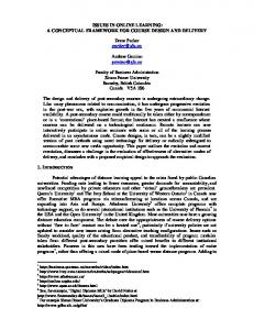
Figure 2. Graphical representation of some task characteristics Generic Characteristics Automation The automation characteristic classifies tasks into three categories: manual, automated, and hybrid. A manual task is performed by humans and does not involve any computing resources. An automated task is performed completely and independently by a computer. A hybrid task involves both computers and humans to complete its operation. Atomicity In our proposed model, we allow a nesting construct to encapsulate a workflow into a task and then use that encapsulated task in some other workflows. This characteristic, called atomicity, distinguishes between the tasks that could be decomposed into workflows and the tasks that could not be decomposed. An atomic task is a single task from the workflow management system’s point of view. A nested task encapsulates a workflow and all the tasks in the encapsulated workflow have to be executed for the successful completion of the nested task. It is possible to have an atomic task that is more complex than a nested task. It all depends on the workflow specifications. As long as it does not decompose into a workflow, we call it an atomic task. Scope Under this classification, we have two types of tasks: external and internal. Most of the tasks in a workflow specification belong to the first category. An external task is any automated or manual activity that is performed to accomplish some business objective. An internal task is a workflow management system activity that is performed to coordinate other external or internal tasks. For example, an internal task may represent a computer program that takes the output from another computer program represented by a preceding external task and generates a condition value required by the proceeding condition object for selecting alternative paths. 6
Workflow Specific Characteristics Placement A task could be placed at three different types of positions on a workflow. If it is the first task in a workflow, it is called an initial task. A last or terminating task is called a final task. All other tasks in a workflow are intermediate tasks. Forcibility A task is called forcible if the underlying system can guarantee that the task will always be successfully executed. Even if a forcible task fails because of a system failure, the workflow management system would keep on trying to repeatedly execute it since it should eventually succeed. The unforcible task may or may not succeed its execution. Compensability In our model, for the tasks that require undo in case of a workflow rollback, an associated compensation task is also defined. This compensation task is executed if a rollback is required and some executed tasks are to be undone at runtime. Under this classification, a task could either be compensable, uncompensable or insignificant. A compensable task could be undone if required and must have an associated compensation task. An uncompensable task cannot be undone in case of a workflow failure. An insignificant task does not require undo and has no impact on the successful rollback of the workflow. Such tasks may be significant for the workflow execution but may or may not have associated compensation tasks because of their insignificant compensation nature. Task compensation is an important aspect of workflow modeling and will be covered under the task failure and recovery management aspect of our methodology. Criticality A critical task, if initiated, must finish its execution for the successful completion of a workflow. A non critical task does not have any affect on the completion of a workflow. Generally, most of the tasks in a workflow are critical. The non-critical tasks are graphically represented by a dotted rectangle. The non critical tasks do not become part of the execution path from an initial task to a final task. These are represented by adding an extra outgoing flow from the preceding task to the non-critical task and having no outgoing flow from the noncritical task. Temporal A temporal task has time constraints attached to it. For example, we may define a deadline for the completion of a particular task. We may also require that a particular task executes only at a specified time of the day or after a specific delay after being initiated. A non temporal task does not have any time constraints and starts executing immediately after initiating and finishes executing as soon as possible and does not have any deadline for completion. The specification of temporal constraints is an important aspect of workflow modeling. Nev7
ertheless, they escalate the complexity of workflow specifications. These characteristics require further investigation and will be covered in the task execution and scheduling constraints aspect of our methodology.
MODELING WORKFLOW CONSTRUCTS Using the workflow modeling objects, we can create workflow specifications by building and joining different constructs. In this section, we define and explain these constructs using sub graphs of example workflow specifications. Ordering The ordering is the most basic construct of workflow modeling and specifies the order in which the tasks in a workflow would be executed by connecting modeling objects with flows. The following example shows a simple ordering construct.
Figure 3. Modeling objects The Task T2 cannot start its execution before T1 has finished executing. Similarly, T3 will only start after T2 has finished executing. The ordering construct enforces sequential execution of tasks within the construct. Alternative The alternative construct is used to model two or more mutually exclusive alternative paths in a workflow. It is constructed by using a condition object and two or more outgoing flows. The condition is a primitive object in our model and depends on external parameters. It takes a set of control and data parameters and a condition value from the preceding task at run time. On the basis of the condition value, it selects one of the alternative workflow execution paths for a given instance of the business process by activating one of its outgoing flows. It is essential in our model that the condition is exclusive and complete. The exclusive characteristic ensures that only one of the alternative paths is selected. The complete characteristic guarantees that, in all instances of the workflow, one of the alternatives shall be selected. We need the complete characteristic to avoid deadlocks at the condition object. The complete characteristic could be achieved by ensuring that the preceding task will always result into one of the possible condition values or by identifying one of the alternatives as default. The following example shows the alternative construct.
8
Figure 4. Alternative and merging constructs After completing its execution, T1 would pass a condition value and a set of data and control parameters to C1. Based on the condition value, C1 would exclusively select either T3, T4 or T5 for execution. Exclusive Join The exclusive join construct is opposite to the alternative construct. It is applied to join two or more mutually exclusive alternative paths into one path by attaching two or more incoming flows to a task or condition object. In Figure 4, the task T6 represents an exclusive join task for T3, T4, and T5. Concurrency The concurrency construct is used to represent two or more concurrent execution paths within a workflow. It is modeled by connecting two or more outgoing flows to a task or synchronizer.
Figure 5. Concurrency and synchronization construct The above example shows the concurrent execution of two paths within a workflow. After completing T1, both T2 and T3 will start executing simultaneously independent of each other. Synchronization The synchronization is opposite to concurrency just as exclusive join is to alternative. It uses the synchronizer object and has two or more incoming flows and one or more outgoing flows. The outgoing flows are not activated until all the incoming flows have been activated. This construct lets us model the situa9
tions where we want two or more concurrent execution paths to complete before proceeding. In Figure 5, the synchronizer S1 will wait for both T2-T4 and T3-T5 paths to complete execution before proceeding to T6.
Figure 6. Possible deadlock situation in synchronization Though synchronization is a very useful construct, it could easily result into deadlocks unless modeled carefully. Figure 6 shows a case where the workflow could get into a deadlock. If the condition value of C1 selects the flow to T3 and C2 selects the flow to S1, then S1 will wait indefinitely for the flow from C1 to activate and would never proceed to T5. However, if C1 and C2 are semantically related to each other in such a way that both of these will take the path to S1 together, but not independently, the workflow will never get into a deadlock situation. This example illustrates a loose potential overview to the problem of deadlocks in workflow specifications. Iteration We need the iteration construct to model the repetition of a group of tasks within a workflow. However, the iteration construct results into a cyclic representation of workflow graphs and thus adds complexity. The iteration is modeled through a condition object. As long as the condition selects an iteration path, a sub graph of the workflow is repeated. Within each iteration construct, at least one flow exists that introduces iteration. We call such a flow an iteration flow. The iteration flow connects the last object in the iteration to the first object of iteration. Furthermore, at least one flow in iteration construct exist, called exit flow, that connects to a path outside the iteration through the condition object.
Figure 7. Iteration construct
10
The above example shows an iteration construct that makes use of concurrency and synchronization construct within the iteration. It is important to note that for each execution of iteration, all the iteration objects would have a new instance with different parameters. The T1 and T6 are two tasks that control the execution of iteration through C1. The flow from T6 to C1 is the iteration flow and the flow from C1 to T2 is the exit flow of the iteration. One of the tasks T3-T6 will change the value of C1 as passed by T1. Start / Stop The initial and final tasks are used to represent the start and stop constructs of workflow specifications. All workflows have one or more initial tasks and one or more final tasks. These two types of tasks represent the alternative initiation and termination of the workflow execution. Even if a workflow has more than one initial and one final task, only one initial and one final task will take part for a specific workflow execution instance.
Figure 8. Workflow with one initial task and two final tasks Generally, an initial task has one or more outgoing flows but no incoming flows. However, it is possible to model an initial task with both incoming and outgoing flows if it is part of an iteration. A final task has one or more incoming flows but no outgoing flows. After a final task completes its execution, the workflow execution is considered successful. We also allow a synchronizer to act as a final task in our model. This is useful when we want a workflow to finish execution after completing two or more concurrent execution paths but do not have a task to perform after the synchronization. By default, all the tasks without an incoming flow are treated as initial tasks. However, the reverse is not true for final tasks. A task without an outgoing flow could either be a final task or a non 11
critical task. A workflow instance has to reach one of the final tasks to complete execution. Figure 8 shows a workflow specification with one initial task T1 and two final tasks T4 and S1. In our model, a workflow may contain disconnected workflow subgraphs. More than one subgraphs allow us to model mutually exclusive alternative user selected execution paths for a business process. We require one or more initial tasks and one or more final tasks for each of the connected workflow subgraphs. A task is the only object in the workflow specifications that performs some work. The condition, synchronizer, and flow objects are internal to a workflow management system and are used to coordinate and control the execution of tasks. Therefore, a workflow specification without a task is not valid. Modeling of more than one initial task provides more than one entry point for the workflow and is similar to the alternative construct. The only difference is that there is no condition object before the alternative initial tasks. More than one initial task is defined when the selection of an initial task is human-oriented and does not depend on a specific condition. Similarly, more than one final task allows us to model alternative paths to complete a workflow. A workflow always starts execution from exactly one of its initial tasks and finishes execution by completing exactly one of its final tasks. Modeling of more than one final task is only possible if we have some alternative constructs in the model. Unless the alternative paths are joined using the exclusive join construct, they would result into mutually exclusive final tasks. Nesting The nesting construct simplifies the workflow specifications through abstraction. Using this construct, we can encapsulate a workflow specification into a task and then use that nested task in other workflow specifications. For each execution of a nested task, the underlying workflow is executed. It is important to perform this nesting in a logical way following a modular approach otherwise it could add complexity to the workflow specifications rather than simplification.
Figure 9. Encapsulation of a workflow into a task 12
The above example uses the nesting construct to represent the workflow specification from the last section. The workflow specification shown on the right side is encapsulated in Task T10 and is used on the left side workflow specification. Contingency The contingency construct is used to define a contingency plan in case of a semantic task failure. We classify task failures into two categories, system failures and semantic failures. A system failure occurs if a task cannot successfully complete its execution because of some problem in or unavailability of the processing entity. For example, if the computer breaks down while processing a task, the workflow would be left into an incomplete state. However, this means that the task would still be able to execute again whenever the computer becomes available. When the system becomes available, the workflow management system would rollback the workflow to a consistent state immediately preceding the failed task and start its execution again. A semantic failure occurs if a task cannot complete its operation because of some underlying task constraints for a specific workflow instance. In this case, a functionally equivalent contingency plan is specified within the workflow. This plan is executed whenever the parent task results into a semantic failure. We represent a contingency plan through the condition object. The following simple example shows the contingency representation for a book issuing workflow of a library. The task T1 is used to access the patron’s record from the database and task T2 to record the book issuing details. In most of the cases, C1 would proceed to T2. In few cases, it is possible that a valid patron does not have a record in the database yet. In this case, T1 would result into a semantic failure and proceed to its contingency plan T1.Cont for entering the patron’s details in the library database.
Figure 10. Contingency representation in workflows Internal Null Tasks The Workflow Management Coalition (1996) identifies four primary control workflow control structures: OR-Split, OR-Join, AND-Split, and AND-Join. These are represented in our model through alternative, exclusive join, concurrency, and synchronization constructs respectively. 13
We have two graphical objects to model the alternative and synchronization constructs: condition and synchronizer. However, the exclusive join and concurrency are represented simply by directly connecting flows to the objects. More than one incoming flows to tasks and conditions represent exclusive join. More than one outgoing flows from tasks and synchronizers represent concurrency. This approach keeps the number of modeling objects to minimum. Nevertheless, in certain cases, it requires the use of null internal tasks whose only purpose is the coordination of flow and compliance to the syntactical correctness criteria of workflow constructs. Figure 11 shows a few cases where the use of internal null tasks is necessary. The internal null tasks have been highlighted in the examples.
Figure 11. Use of internal null tasks Identifying Constructs Table 1 summarizes the identification of constructs on the basis of object types and the number of incoming and outgoing flows connected to them. Primarily, there are three types of objects in our model, tasks, conditions, and synchronizers, that are interconnected through flows to build workflow graphs. Each object may have none, one, or more than one incoming or outgoing flows attached to it. The number of such flows could be used to identify the type of construct each object is involved in. For example, Table 1 shows that more than one incoming flows to a task build an exclusive join construct. Table 1. Identification of constructs Incoming Flows Outgoing Flows Objects None 1 >1 None 1 >1 Task 1 O F,N O O C Condition X O X X X A Synchronizer X X F O O C O: Simple Ordering, A: Alternative, J: Exclusive Join, C: Concurrency, S: Synchronization, I: Initial Task, F: Final Task, N: Non Critical Task, X: Illegal 14
SYNTACTICAL CORRECTNESS OF WORKFLOWS We use the constructs defined in the previous section to build workflow specifications. A CASE tool for process definition is an important component of a workflow management system and is applied for workflow modeling. It is possible to easily get into error situations while building complex workflow specifications. The identification of these errors is obvious and trivial for workflows that consist of only a few objects. However, the verification of workflow conceptual specifications containing a large number of objects is known to be complex (ter Hofstede et al 1996). The extensive use of condition and synchronizer objects in workflows further increase the complexity of some verification problems. This inherent difficulty of manually verifying the correctness of workflows makes a strong case for the development of an automated verification engine. Such an engine would become an essential component of a process definition CASE tool for workflows. The early detection of errors in workflow specifications during the modeling stage is of vital importance and facilitates the development of reliable and correct workflow applications. The identification of a set of constraints for avoiding errors in workflow specifications is the first step towards developing a verification engine. In this section, we identify and explain these correctness constraints. We classify the workflow specification errors into two categories: syntactic and semantic. The invalid use of workflow modeling constructs results into syntactical errors. To verify the syntactical correctness of the model, we do not need the information regarding the underlying operations of the tasks and their processing entities. For example, a condition node with only one outgoing flow is a syntax error. It means that the condition node does not have any alternatives to select from. The semantic errors occur due to incorrect modeling of business processes or getting into error situations because of some certain combinations of task execution. To verify the semantic correctness we need information about the internal structure of tasks. For example, a condition node selects one of the outgoing flows based on the conditional values provided by the preceding task. Assume we have a condition node with two outgoing flows selected on values V1 and V2 respectively. The construct is semantically correct as long as we could guarantee that the preceding task would always result into either of the above mentioned values. However, if the condition value is anything but V1 or V2, it would result into a deadlock for the workflow instance because of a semantic error in the modeling. We have identified five types of possible syntactical errors in a workflow model: • incorrect usage, e.g., a synchronizer object with only one incoming flow; • deadlocks, e.g., synchronization on two mutually exclusive alternative paths; • livelocks, e.g., iteration with no exit path; 15
• unintentional multiple execution, e.g., merging on two concurrent paths; • active termination, e.g., concurrent paths leading to more than one final tasks. We classify the workflows correctness constraints into two categories, simple and complex, on the basis of their algorithmic complexity.
Simple 1.
2.
All flows must have two different objects connected to their two sides. A flow is used to represent the flow of information form the object that is connected to its starting side to another object on its ending side, therefore an empty side is invalid. Similarly, we do not allow the same object on both sides of an object since it would result into a never ending iteration without a condition. There should not be more than one direct flows between any two objects. Since a single flow could represent the flow of any information between two objects, there is no need for having two independent flows between the same two objects.
Figure 12. Examples of constructs violating rule 1 and 2 3.
4.
5.
All conditions must have at least one incoming and two outgoing flows. A condition is used to select one of the two or more alternative execution paths. A condition with only one outgoing path represents a trivial construct where the condition is unnecessary, hence such a construct is invalid. All synchronizers must have at least two incoming flows. A synchronizer waits for all incoming flows to activate before proceeding. A synchronizer with only one incoming flow represents a trivial construct where the synchronization is unnecessary, therefore such a construct is not allowed. A non critical task must not have an outgoing flow, it must not have a condition object as its preceding node, and its preceding node must have at least one outgoing flow to an object other than a non critical task. Non critical tasks have limited usage in workflows and require specific verification treatment. First, we require that non critical tasks do not have outgoing flows so that they do not occur in a direct workflow execution path from an initial task to a final task. Second, if a non critical task has a condition as its preceding node, the workflow would not reach a final task if it selects the path to non-critical task. Third, we ensure that the preceding node to a non critical task has at least one outgoing flow that leads to a final task.
16
Figure 13. Non critical task usage 6.
Each connected workflow subgraph must contain at least one initial and one final task. The tasks are the only objects in workflow specifications that perform some work, therefore, a workflow without a task is invalid. It is necessary to identify at least one of the tasks as an initial task since it is the only way to represent a valid starting point of a workflow. By default, all tasks without incoming flows represent initial tasks. However, in some cases, as shown in Figure 14, if an initial task is part of an iteration path, it is necessary to explicitly identify it. On the other hand, a task without an outgoing flow could either be a final task or a non critical task. Only a critical task or a synchronizer without outgoing flows represents a final task.
Figure 14. Initial task within iteration construct Complex 7.
All or none of the flows preceding a synchronizer activate for all possible instances of a workflow. This rule eliminates the possibility of a synchronizer deadlock. A deadlock occurs in execution, if an incoming flow to a synchronizer would not activate in one of the possible execution instances of the workflow specification. A workflow without an alternative construct would produce exactly one workflow instance graph that is equivalent to the workflow definition graph. However, if alternative constructs are used in a workflow graph, there would be more than one possible workflow instance graph, each of which would be a subset of the workflow definition graph. A deadlock occurs if we model the synchronization of mutually exclusive alternative paths. In the following example, if C1 takes the path to T2, the Synchronizer S1 will wait indefinitely for T3 to finish. Reversaly, if C1 takes the path to T3, S1 will wait indefinitely for T2 to finish. 17
Figure 15. Example of a synchronizer deadlock 8.
Only one or none of the flows leading to a task or a condition activates for all possible instances of a workflow. This rule eliminates the possibility where a task is activated more than once from two different execution paths. Generally, every task will have only one incoming flow. If it is preceded by concurrent execution paths, a synchronizer is used just before the task to wait for all the concurrent execution paths to finish. In some cases, the task is preceded by alternative execution paths. In such cases, a synchronizer can not be used and all the incoming flows are connected to the task through the exclusive join construct. This rule ensures that all the incoming flows to a task or a condition are mutually exclusive. In the following example, T1 would concurrently activate T2 and T3. Both T2 and T3 would activate T5 after their completion independently, resulting in unintentional multiple execution of T5 and the path following T5.
Figure 16. Example of unintentional multiple execution 9.
None of the workflow objects is activated more than once for each of the possible instances of a workflow unless it is part of an iteration. This rule eliminates the modeling of a loop without condition in the workflow specifications. The only type of loop that is allowed in workflow specifications is through iteration. The following diagram shows a construct that violates this rule.
Figure 17. Example of a Loop without Condition 10. A workflow always reaches exactly one of its final tasks for each of its possible instances. This rule avoids the incomplete termination of a workflow. 18
A workflow is incompletely terminated if it finished executing one of its final tasks while some other critical tasks in the workflow were still executing. This could only happen if there are concurrent execution paths in a workflow that are not synchronized before terminating a workflow. The following workflow violates this rule.
Figure 18. Invalid Multiple Final Tasks 11. All concurrent paths initiating between the first and last objects of iteration path must be synchronized before the last object of the iteration path. Without iteration construct, the workflow model is represented by a simple acyclic directed graph. The iteration construct introduces cycles in the workflow graph and hence makes the syntactical verification more complex. This rule ensures that the objects within the iteration path do not activate some other object outside the iteration path while the iteration is in progress. Such an activation would result into unintentional multiple execution of a workflow path that is not part of the iteration. In the following example, the flow from T3 to T5 takes the execution flow to a path that is outside the iteration construct.
Figure 19. Invalid Iteration Construct 12. The condition object controlling the iteration must have at least one of its alternative paths leading to a final task. This rule prohibits the modeling of livelocks through iteration. It ensures that at least one of the paths from iteration leads to a final task. The following example shows a workflow where all outgoing flows from C1 are part of iteration and thus resulting into a livelock.
19
Figure 20. Livelock in Iteration Construct
IMPLEMENTATION OF CORRECTNESS ALGORITHMS A workflow conceptual model is represented by a set of directed graphs having tasks, conditions and synchronizers as their vertices and flows as edges. The rules for verifying the syntactical correctness of workflow graphs are implemented using graph algorithms. The algorithms to implement these correctness constraints depend on the implementation of workflow repository. For example, if the repository is defined in a relational database, the specifications could be verified by implementing algorithms based on SQL queries running on workflow repository. The implementation of these correctness rules is applied to develop a syntactical verification engine for a CASE tool for modeling workflow graphs. Some of the algorithms for complex constraints are exponential in nature. However, It is possible to reduce the workflow graph first, by removing the syntactically correct subgraphs from it, before running the algorithms for complex rules. We have developed a prototype for the graphical modeling of workflow and a verification engine that incorporates algorithms for some of the correctness constraints described in the previous section. The graphical modeling prototype stores the workflow graph information in a repository as nodes and edges. The verification engine uses this graph information of workflows identify the error situations in the workflow model.
CONCLUSIONS We have presented a graphical conceptual modeling technique for workflows. The graphical modeling objects include tasks, conditions, synchronizers, and flows. The task is the primary object in workflow specifications and has several generic and workflow specific characteristics. Using the four modeling objects, following workflow modeling constructs are identified: ordering, alternative, exclusive join, concurrency, synchronization, iteration, start/stop, nesting, and contingency. These constructs are used to specify rules and constraints for workflow execution. The workflow specifications are built using a combination of modeling constructs. These specifications may contain syntactic and semantic modeling errors. We have presented a set of constraints for identifying and avoiding the syntactical errors in workflow specifications. 20
The primary motivation behind this paper is to present a framework for the development of a workflow modeling CASE tool. The two aspects, covered in this paper, of such a CASE tool would be applied to facilitate the modeling and verification of workflow graphs. The workflows are represented by directed graphs having tasks, conditions and synchronizers as their vertices and flows as edges. One of the ways to verify the syntactical correctness of workflows is to apply graph algorithms. We have developed a prototype for the graphical modeling of workflows and implemented a verification engine that incorporates algorithms for some of the correctness constraints presented in this paper.
REFERENCES Alonso G, Agrawal D, El Abbadi A, Kamath M, Guenthoer R and Mohan C (1996) Advanced Transaction Models in Workflow Contexts. In Proceedings of the 12th International International Conference on Data Engineering, New Orleans. Attie PC, Singh MP, Sheth A and Rusinkiewicz M (1993) Specifying and Enforcing Intertask Dependencies. In Proceedings of the 19th VLDB, Dublin, Ireland. Breitbart Y, Deacon S, Schek HJ, Sheth A and Weikum G (1993) Merging Application-centric and Data-centric Approaches to Support Transactionoriented Multi-system Workflows. Sigmod Record, 22(3). Casati F, Ceri S, Pernici B and Pozzi G (1995) Conceptual Modeling of Workflows. In M.P. Papazoglou, editor, Proceedings of the OOER’95, 14th International Object-Oriented and Entity-Relationship Modeling Conference, volume 1021 of Lecture Notes in Computer Science, pages 341-354. SpringerVerlag. Casati F, Ceri S, Pernici B and Pozzi G (1996) Workflow Evolution. In Proceedings of the 15th International Conference on Conceptual Medelling, ER’96, Cottbus, Germany. Springer Verlag, Lecture Notes in Computer Scence. Ellis CA and Nutt GJ (1993) Modeling and Enactment of Workflow Systems. In Applicatrion and Theory of Petri Nets. M. Ajmone Marasan Ed., volume 691 of Lecture Notes in Computer Science, New York. Springer-Verlag. Georgakopoulos D, Hornick M and Sheth A (1995) An Overview of Workflow Management: From Process Modeling to Workflow Automation Infrastructure. Journal on Distributed and Parallel Databases, 3(2):119-153. ter Hofstede AHM, Orlowska ME and Rajapakse J (1996) Verification Problems in Conceptual Workflow Specifications. Technical Report No. 363, Department of Computer Science, The University of Queensland, Australia. ter Hofstede AHM, Orlowska ME and Rajapakse J (1996) Verification Problems in Conceptual Workflow Specifications. In Proceedings of the 15th International Conference on Conceptual Medelling, ER’96, Cottbus, Germany. Springer Verlag, Lecture Notes in Computer Scence, pp. 73-88. Kuo D, Lawley M, Liu C and Orlowska ME (1996) A General Model for Transactional Workflows. In Proceedings of the International Workshop on Advanced Transaction Models and Architecture. Goa, India. ATMA’96, pp. 18-35. 21
Kamath M and Ramamritham K (1996) Bridging the gap between Transaction Management and Workflow Management. In Proceedings of the NSF Workshop on Workflow and Process Automation in Information Systems: State of the Art and Future Directions, Athens, Georgia. Kamath M and Ramamritham K (1995) Modeling, Correctness & Systems Issues in Supporting Advanced Database Applications Using Workflow Management Systems. Computer Science Technical Report 95-50, University of Massachusetts, Massachusetts Rajapakse J and Orlowska ME (1995) Towards a Graphical Transactional Workflow Specification Language. In Proceedings of the Australian Systems Conference. Rusinkiewicz M and Sheth A (1994) Specification and Execution of Transactional Workflows. In W. Kim, editor, Modern Database Systems: The Object Model, Interoperability, and Beyond. Addison Wesley. Sadiq W and Orlowska ME (1996) Modeling and Verification of Workflow Graphs. Technical Report No. 386, Department of Computer Science, The University of Queensland, Australia. Workflow Management Coalition (1996) The Workflow Management Coalition Specifications - Terminology and Glossary. Issue 2.0, Document Number WFMC-TC-1011.
22