IEEE SIGNAL PROCESSING LETTERS, VOL. 14, NO. 10, OCTOBER 2007
649
On Crosstalk Cancellation and Equalization With Multiple Loudspeakers for 3-D Sound Reproduction Yiteng (Arden)Huang, Member, IEEE, Jacob Benesty, Senior Member, IEEE, and Jingdong Chen, Member, IEEE
Abstract—People prefer to be able to enjoy spatial audio without wearing a headphone. Such a tethered device is anyway inconvenient and undesirable, if not cumbersome. Alternatively, 3-D sound can be delivered to a listener with loudspeakers. However, crosstalk arises, and the rendered binaural signals are distorted by room reverberation when arriving at the listener’s two ears, which lead to the need for a crosstalk cancellation and equalization (CTCE) system. Classical CTCE systems employ only two loudspeakers, and their performance is usually unsatisfactory in practice. While the idea of using more loudspeakers has been investigated, it was never shown why using more loudspeakers is theoretically more advantageous for CTCE. In this letter, we will study this problem and demonstrate that with two loudspeakers, only a least-squares (LS) solution can be obtained, while using multiple loudspeakers, we have more options: either an LS solution or an exact solution for perfect CTCE. These findings are justified by simulations using real impulse responses measured in the varechoic chamber at Bell Labs. Index Terms—Crosstalk cancellation, equalization, inverse filtering, multichannel acoustic signal processing, 3-D sound reproduction.
I. INTRODUCTION
T
HE 3-D audio technology based on head-related transfer functions (HRTFs) (for synthesizing binaural signals) can position sound sources in 3-D space with only a two-loudspeaker presentation [1]. This is not possible with classical stereo systems. Therefore, 3-D systems have the potential to be used in many applications such as computer gaming and multiparty teleconferencing over the IP networks, where there is a great need for the participants to be able to differentiate competing sounds or voices. However, the delivery of these binaural signals to the listener’s ears (assuming that loudspeakers are used and not headphones) is not straightforward. Indeed, each ear receives the so-called crosstalk components, and moreover, the direct signals are distorted by the reverberation of the room. Therefore, an inverse filter is required before playing out the binaural signals through the loudspeakers. The concept of crosstalk cancellation and equalization (CTCE) was first invented by Atal and Schroeder [2] and Bauer
Manuscript received February 13, 2007; revised March 14, 2007. The associate editor coordinating the review of this manuscript and approving it for publication was Prof. Alfred Hanssen. Y. Huang and J. Chen are with Bell Laboratories, Alcatel-Lucent, Murray Hill, NJ 07974 USA (e-mail:
[email protected];
[email protected]). J. Benesty is with the Université du Québec, INRS-EMT, Montréal, QC H5A 1K6, Canada (e-mail:
[email protected]). Color versions of one or more of the figures in this paper are available online at http://ieeexplore.ieee.org. Digital Object Identifier 10.1109/LSP.2007.898329
Fig. 1. Schematic diagram of a classical CTCE system using two loudspeakers.
[3] in the early 1960s. Many other sophisticated algorithms have been proposed since then, using two or more loudspeakers for rendering the binaural signals. Most of these algorithms are based on least-squares techniques [4]–[7]. II. CLASSICAL LEAST-SQUARES APPROACH WITH TWO LOUDSPEAKERS The least-squares approach is the most used technique for CTCE. In this section, we explain this method in a two-loudspeaker presentation and try to show why it may be limited in practice. Let and be the binaural signals ( is the time index), and the two loudspeaker signals, and and the signals at the listening points (i.e., the two ears). , in such a way The objective is to find the filters that crosstalk signals are suppressed and the effect of the channel impulse responses ( , ) from the loudspeakers to the ears is reduced. This is equivalent to demanding ideally , , 2, with being a constant delay. See Fig. 1 for the principle of this scheme. The loudspeaker signals are (1) where the operator “ ” denotes convolution. We can now write the signals at the listener’s ears as (2) Substituting (1) into (2), we get
1070-9908/$25.00 © 2007 IEEE
(3)
650
IEEE SIGNAL PROCESSING LETTERS, VOL. 14, NO. 10, OCTOBER 2007
which we can put in a more convenient vector/matrix form as follows: (4) where
denotes a vector/matrix transpose
is a matrix of size
is an FIR filter of length and , respectively
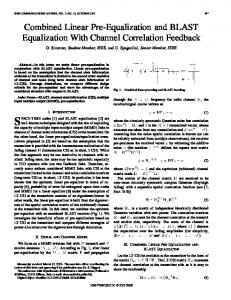
, whose input and output are Fig. 2. Illustration of the proposed CTCE system using three loudspeakers for 3-D sound reproduction.
is the channel impulse response matrix of size
, with
Fourth, it is very well known that this method is not very robust to head movements [8]. III. APPROACH TO CTCE WITH MORE LOUDSPEAKERS
.. .
..
.
..
.
..
.
..
.
.. .
is a Sylvester matrix of size
is the acoustic impulse response, of length loudspeaker to the th ear, and
, from the
th
is a vector containing the most recent samples of the source signal . The conditions for CTCT are mathematically expressed as follows:
In this section, we are going to show that by using channel diversity (i.e., using more than two loudspeakers), more options are available to us to find a robust and reliable solution to our problem. and , but Here again we have our binaural signals loudspeakers to try rendering the this time, we will use sound as exactly as possible at the listener’s ears. Fig. 2 depicts the principle of this approach with . Using the same notation as the previous section, we can easily see that the signals at the listener’s ears are (7) where this time
(5) where is a vector of length , whose th component is equal to 1, and is also a vector of length containing only zeroes. Assuming that has full column rank and , it is easy to see from (5) that this linear system . In this has more equations than unknowns since situation, the best (and only) estimator that we can derive from (5) is the least-squares solution, i.e., (6) However, this solution may not be good enough in practice for several reasons. First, we do not know how to determine . may not even be of full rank. Third, from this apSecond, proach, it is not clear what LS does best, crosstalk cancellation or equalization. In other words, we cannot quantify in a clean way the residual crosstalk signals or the equalization error.
.. . is a matrix of size
.. .
, and
is the channel impulse response matrix of size We now deduce the conditions for CTCE as follows:
.
(8) The linear system (8) has equations and unknowns. Assume that has full column rank. Depending on how we choose , we have three very different solutions.
HUANG et al.: CROSSTALK CANCELLATION AND EQUALIZATION WITH MULTIPLE LOUDSPEAKERS
651
A. Least-Squares Solution
A. Performance Measures
To obtain the least-squares solution [10], we should take in such a way that , which implies that . Therefore
In this letter, two performance measures are employed: signal-to-crosstalk ratio (SCTR) and signal-to-distortion ratio (SDR). Let us first denote (12) (9) So what the th ear hears due to the signal
where is a nonnegative regularization factor and is the identity matrix of size . Regularization is used to reduce its sensitivity to errors in the measured impulse responses [9].
is found as (13)
Therefore, the SCTR at the two ears would be (14)
B. Exact Solution An exact solution can be derived if we can make a square matrix. This is possible if , which implies that if the result of such division is an integer. Hence
denotes mathematical expectation. Substituting where (13) into (14) leads to (15)
(10)
This solution can be obtained if we decide to have more equa. Hence tions than unknowns [10], i.e.,
where , , 2 is the autocorrela. In general, the SCTRs depend not only on tion matrix of but also on the binaural signals. Since our the CTCE filters interest is merely in the CTCE system, without any loss of generality, we can assume that the binaural signals are white and have the same strength. Then . Consequently, the SCTRs are calculated as follows:
(11)
(16)
C. Minimum-Norm Solution
The first important thing to notice is that, compared to the two-loudspeaker presentation, we have a pretty good idea on how to determine the length of the CTCE filters . While this number of FIR filters is doubled, its required length will probably be much smaller than the length of the filters of the classical least-squares solution (with two loudspeakers), with likely much better performances. The least-squares technique may be the most interesting in practice since it gives an upper bound for . Moreover, may not be full column rank. In this case, we can reduce the length until we get an acceptable solution. The exact solution can be seen as a generalization of the multiple-input/output inverse theorem (MINT) [11]. Recall that the MINT can exactly equalize any number of points in a room using a monaural signal only. Here, we generalized the idea to binaural signals. The minimum-norm solution seems useless from a practical system design point of view because there is no good reason why we should choose much longer than necessary. In parfor the ticular, when the number of used loudspeakers is low, minimum-norm solution can be much longer than the length of the acoustic impulse responses .
IV. SIMULATIONS In this section, we evaluate the performance of the proposed CTCE algorithm in a comparison with the classical method by simulations.
and the average SCTR is given by . At the th ear, the signal distortion is defined as (17) Substituting (13) into (17) produces (18) Then the SDR at the th ear is determined by
(19) Using the assumption of white binaural signals, we deduce that (20) and the average
.
B. Simulation Setup The simulations were carried out using the impulse responses measured in a real, reverberant environment: the
652
IEEE SIGNAL PROCESSING LETTERS, VOL. 14, NO. 10, OCTOBER 2007
TABLE I PERFORMANCE OF A CTCE SYSTEM USING VARIOUS NUMBERS OF LOUDSPEAKERS AND IN DIFFERENT ACOUSTIC ENVIRONMENTS
Fig. 3. Floor plan of the varechoic chamber at Bell Labs (coordinate values measured in meters).
varechoic chamber at Bell Labs [12]. The chamber is a rectangular room with 368 electronically controlled panels that vary the acoustic absorption of the walls, floor, and ceiling [13]. Therefore, the level of room reverberation is well controlled by the percentage of open panels. Three panel configurations were investigated: 75%, 30%, and 0% open panels. Their average reverberation times are approximately 310 ms, 380 ms (moderately reverberant), and 580 ms (highly reverberant), respectively. The original impulse responses were measured at 8 kHz and had 4096 samples. For the three panel configurations, the impulse responses were truncated to , 380, and 580 samples, respectively. Gaussian random noise is added in the impulse responses with 30 or 15 dB signal-to-noise ratio (SNR). The regularization factor is specified as 0.01 and 0.5, respectively, at 30 and 15 dB SNR. We investigated using two and three loudspeakers for CTCE. The positions of the loudspeakers and the two microphones (to simulate a listener’s two ears) are shown in Fig. 3. C. Simulation Results The simulation results are summarized in Table I. It is clearly demonstrated that the performance of a CTCE system is significantly improved by using multiple loudspeakers in either lightly or heavily reverberant environments. If is chosen such that the number of parameters (denoted as , which determines the computational complexity of the CTCE algorithm) is the same, a CTCE system using three loudspeakers at 15 dB SNR can achieve almost the same performance as a CTCE system using only two loudspeakers at 30 dB SNR. In the case of using three loudspeakers, the exact solution is ideal in the absence of noise in the impulse responses. However, in practice, where the impulse responses cannot be precisely measured, the study suggests to use an LS algorithm and choose a that is only slightly smaller than . V. CONCLUSIONS CTCE is a challenging problem, but it is critical for handsfree 3-D sound reproduction. It has been reported that the performance of a CTCE system using only two loudspeakers is usually unsatisfactory in practice. In this letter, we analyzed the problem with use of multiple (more than two) loudspeakers. We showed
mathematically that using two loudspeakers only an LS solution can be obtained. Using multiple loudspeakers was recommended. We further showed that by using more loudspeakers, we can take advantage of acoustic channel diversity and get either an LS or an exact solution by choosing a proper length for the CTCE filters. As a result, we can design a more robust CTCE system that is less sensitive to errors in the measured impulse responses. Finally, these analyses were justified by simulations using real impulse responses measured in the varechoic chamber at Bell Labs. REFERENCES [1] C. Avendano, “Virtual spatial sound,” in Audio Signal Processing for Next-Generation Multimedia Communication Systems, Y. Huang and J. Benesty, Eds. Boston, MA: Kluwer, 2004, ch. 13, pp. 345–370. [2] B. S. Atal and M. R. Schroeder, “Apparent Sound Source Translator,” U.S. Patent 3,236,949, Feb. 1966 (filed 1962). [3] B. B. Bauer, “Stereophonic earphones and binaural loudspeakers,” J. Audio Eng. Soc., vol. 9, pp. 148–151, 1961. [4] P. A. Nelson, H. Hamada, and S. J. Elliott, “Adaptive inverse filters for stereophonic sound reproduction,” IEEE Trans. Signal Process., vol. 40, no. 7, pp. 1621–1632, Jul. 1992. [5] S. M. Kuo and G. H. Canfield, “Dual-channel audio equalization and cross-talk cancellation for 3-D sound reproduction,” IEEE Trans. Consum. Electron., vol. 43, no. 4, pp. 1189–1196, Nov. 1997. [6] A. Mouchtaris, P. Reveliotis, and C. Kyriakakis, “Inverse filter design for immersive audio rendering over loudspeakers,” IEEE Trans. Multimedia, vol. 2, no. 2, pp. 77–87, Jun. 2000. [7] S. Miyabe, M. Shimada, T. Takatani, H. Saruwatari, and K. Shikano, “Multi-channel inverse filtering with selection and enhancement of a loudspeaker for robust sound field reproduction,” in Proc. IWAENC, 2006, pp. 1–4. [8] D. B. Ward and G. W. Elko, “Effect of loudspeaker position on the robustness of acoustic crosstalk cancellation,” IEEE Signal Process. Lett., vol. 6, no. 5, pp. 106–108, May 1999. [9] Y. Tatekura, Y. Nagata, H. Saruwatari, and K. Shikano, “Adaptive algorithm of iterative inverse filter relaxation to acoustic fluctuation in sound reproduction system,” in Prof. Int. Congr. Acoustics, 2004, vol. IV, pp. 3163–3166. [10] T. K. Moon and W. C. Stirling, Mathematical Methods and Algorithms. Upper Saddle River, NJ: Prentice-Hall, 1999. [11] M. Miyoshi and Y. Kaneda, “Inverse filtering of room acoustics,” IEEE Trans. Acoust. Speech, Signal Process., vol. ASSP-36, pp. 145–152, Feb. 1988. [12] A. Härmä, Acoustic Measurement Data From the Varechoic Chamber, Technical Memorandum, Agere Systems, Nov. 2001. [13] W. C. Ward, G. W. Elko, R. A. Kubli, and W. C. McDougald, “The new Varechoic chamber at AT&T Bell Labs,” in Proc. Wallance Clement Sabine Centennial Symp., 1994, pp. 343–346.