increasing pipeline depths, and extensive support logic in microprocessor designs .... The distinction between these definitions and the classic definition of temporal ..... tion was done on an IBM RISC System/6000 running. AIX3.2.4 with the ...
ON EFFECTIVE DATA SUPPLY FOR MULTI-ISSUE PROCESSORS* Jude A. Rivers, Edward S. Tam, and Edward S. Davidson Advanced Computer Architecture Laboratory Electrical Engineering and Computer Science Department The University of Michigan Ann Arbor, MI 48109-2122 {jrivers,estam,davidson}@eecs.umich.edu Abstract Emerging multi-issue microprocessors require effective data supply to sustain multiple instruction processing. The data cache structure, the backbone of data supply, has been organized and managed as one large homogenous resource, offering little flexibility for selective caching. While memory latency hiding techniques and multi-ported caches are critical to effective data supply, we show in this paper that even ideal non-blocking multi-ported caches fail to be sufficient in and of themselves in supplying data. We evaluate an approach in which the first level (L1) data cache is partitioned into multiple (multi-lateral) subcaches. The data reference stream of a running program is subdivided into two classes, and each class is mapped to a specific subcache whose management policy is more suitable for the access pattern of its class. This sort of selective organization and caching retains more useful data in the L1 Cache, which translates to more cache hits, less cache-memory bus contention and overall improvement in execution time. Our simulations show that a multi-lateral L1 cache of (8+1)KB total size generally performs as well as, and in some cases better than, an ideal multiported 16KB cache structure in supplying data.
1. INTRODUCTION Demands for high performance microprocessors call for more aggressive exploitation of fine grain parallelism at the uniprocessor instruction level. Instruction level parallelism (ILP) allows for multiple instruction issue and processing during a clock cycle, constrained mainly by the dependencies among program instructions and the availability of processor functional resources. Aggressive efforts towards issuing up to 16 instructions (i.e. an average of three basic blocks) per clock cycle [1] are already underway. Achieving such a high ILP exploitation requires a closer compiler and microarchitecture alliance in dealing *This work was supported by a gift from IBM and a University of Michigan Graduate Fellowship, and used resources of the University of Michigan Center for Parallel Computing, which is partially funded by NSF grant CDA-92-14296.
b) Instruction Processing Instruction Fetch & Decode
Instruction Issue Queues
Integer Units
&
FP Units
Reorder Buffer Instruction Cache
c) Data Supply LD/ST Units
a) Instruction Supply Data Cache
.
d1 d2 .. dn
Data Cache (partitioned)
Figure 1: A structural partition of a dynamic superscalar processor showing the three sections. Figure also shows partitioning of the data cache into a multi-resource. Resulting subcaches d1, d2,..., dn can each be a different size with different parameters. with the three critical sections of the dynamic superscalar processor: instruction supply, data supply and instruction processing, as shown in Figure 1. Instruction supply covers processor resources and techniques that ensure that multiple instructions per clock are fed to the instruction processing section. Recent extensive literature on branch prediction, e.g. [2][3], high bandwidth fetch mechanisms, e.g. [4][5], and issue mechanisms demonstrates the importance of this stage to performance. Instruction processing deals generally with the availability of sufficient execution resources to ensure concurrent execution: functional units, bypass logic for forwarding operands, and the necessary interconnects that link various parts of the processor structure. Technological advancements in VLSI design will allow progressively more functionality to be placed within a single chip. Hence, the current trends of replicated functional units, increasing pipeline depths, and extensive support logic in microprocessor designs will likely continue. Data supply is concerned with processor resources and techniques that support the data demands of the issued instructions: the data memory hierarchy (caches and pri-
mary memory) as well as the management and techniques responsible for moving elements within the hierarchy and to the CPU. In particular, on-chip cache memories commonly serve as the head of the data memory hierarchy. However, an on-chip data cache is only beneficial if the internal state is organized and managed in such a way that requested data is supplied within a short cycle time. Multiissue processors are now capable of making multiple data requests per clock cycle. For example, with about a third of a program’s instruction mix [6] being memory references, an average of 5 load/stores per cycle would be necessary to sustain a 16-wide issue processor. Stalls due to data cache misses are particularly intolerable for processors that rely on efficient scheduling to exploit ILP. For such processors, cache misses can disrupt the compiler generated ILP schedule, and adversely affect performance. For efficient data supply, the first-order factors are the available bandwidth to the primary (L1) data cache and the management of its internal state. In this paper, we emphasize the structure and management issues of the L1 data cache. We believe that current cache management approaches threaten to render the data cache a major bottleneck for multi-issue processors. The naive approach of uniformly placing all referenced data in the cache, irrespective of their reuse behavior, fails to scale well with issue bandwidth. We show the benefits of adopting a dynamic behavior-conscious approach to data cache management. With increasing demand on data supply bandwidth, multiple ports from the processor to the cache are needed. Ideally, for a processor with multiple ports, we would expect each port to operate independently. Although current techniques of multi-port implementation (replicating the cache or interleaving the cache) do not attain this ideal performance, in this work we assume ideal ports. As we show later, even ideal non-blocking multi-ported caches fail to be sufficient in and of themselves. Apparently, if the internal state of the L1 data cache is not well organized and managed, numerous ports from the processor to the cache cannot ameliorate the effects of data cache misses. In the rest of this paper, Sections 2 and 3 make a case for partitioning the data cache into a multi-lateral resource, where each sub-resource is organized and managed in accordance with fitting criteria. Section 4 discusses our simulation environment and presents results, using a full multi-issue processor model. To illustrate the need for efficient management of the internal state of the L1 data cache, we isolate the cache effects on processor performance. Section 5 concludes this work.
2. MANAGING L1 DATA CACHE STATE For an on-chip data cache to be most beneficial to emerging processors, it must be fast and small with little
or no associativity; large highly-associative caches are not viable solutions to the data supply problem. The use of expensive fast SRAM in large caches greatly increases system cost. Furthermore, the size and resulting logic complexity of high associativity can substantially increase cache access time. This apparent limitation in the size, organization and speed of L1 data caches therefore makes the direct-mapped configuration a preferred choice, especially considering its short cycle time [7]. Small directmapped caches, however, suffer from high miss rate. Cache misses, in a uniprocessor environment, can be categorized into three groups: compulsory, capacity and conflict [8]. Compulsory misses, associated with the first access to a data block, are eliminated only by prefetching. Capacity misses result from referencing more active data than can fit in the cache, and conflict misses are additional misses due to cache block interferences within a set. Unfortunately, direct-mapped caches have the most conflict misses since they can only store one memory block per cache set. Cache designs can benefit from hybrid schemes [9] that attempt to combine the fast access of direct-mapping with the lower miss rate of set-associativity, at reasonable cost by exploiting the non-uniformity of the data reference stream with selective caching.
2.1. Program and Data Reference Behavior Conventional cache management policies do not consider program reference behavior in their data placement policies which are location insensitive. The placement location is a function of the address referenced, not the reference behavior. Abraham et al. [10] showed that a relatively small fraction of load/store instructions account for a large majority of memory references, and an even much smaller fraction of these account for most data cache misses. Furthermore, a large fraction of memory references are made by instructions that miss extremely infrequently [10][11]. Both [10] and [11] recommend the specific labeling of load/store instructions and the use of special cache control instructions to assist in selective caching of the referenced data. Even with specially labeled instructions, deciding where to place the referenced data in the cache structure based on the instruction is equivalent to treating all data referenced by this instruction to be of uniform behavior. Such uniformity, however, may not exist and this can result in poor management of the internal cache state, and provide minimal benefit in exploiting a code’s temporal (and/or spatial) locality. In a broader sense, the efficacy of a cache structure is ruled by its ability to maintain a balance between exploiting temporal and spatial locality. Conventional cache designs attempt to exploit spatial locality by choosing some fixed cache block size (often large) across all applications, and temporal locality by loading every referenced block into the cache without regard for its reuse behavior.
A closer look at underlying cache behavior, however, reveals additional factors that affect the ability to exploit locality. An application’s spatial locality is often predictable from the source code and cache misses may be predictable for a given block size and cache organization. However, temporal locality may be much more difficult to exploit. Exploiting the locality in an application’s data reference stream is thus affected by many factors: cache size, cache block size, degree of associativity, and the program execution style with respect to how references are presented to the cache.
2.2. The Cache Block Conflict Problem Data cache items can be accessed with varying usage patterns, especially in the multi-issue processor environment. A clear consequence is the chance that reusable data will be displaced from the cache by use-once and/or superfluous data, creating the problem of cache pollution. This problem is further exacerbated by the need to limit the L1 data cache to direct-mapping, in order to close the processor-memory speed gap. Active regions of memory (i.e. the working set of a running application) can be grouped into two major categories: dynamic temporal and dynamic non-temporal. In direct-mapped caches, the block conflict problem is more pronounced. As noted above, temporal reuse behavior is better exploited by some cache designs than others. Accordingly, we define the following: Definition 1: A block being replaced in the cache is considered dynamic temporal (T) if during this lifetimea and each of its previous lifetimes, at least one of its words was rereferenced. Definition 2: A block being replaced in the cache is considered dynamic non-temporal (NT) if during this lifetime or one of its previous lifetimes, none of its words was rereferenced. The distinction between these definitions and the classic definition of temporal behavior is that the granularity for determining temporal reuse is at the word, rather than the block level. A cache block that is regarded as temporal in the classical sense, can be classified as NT based on reuse patterns of its words during a cache lifetime. The reverse is also true, i.e., a classically defined non-temporal block can be accessed with dynamic temporality if its lifetimes are extended. Both T and NT blocks can be spatial if more than one word is referenced during a block’s lifetime, or non-spatial, if only a single word is accessed. In most applications, a significant number of data items are referenced frequently in an interleaved fashion in what we describe as the T reference pattern. Such patterns a. A lifetime of a cache block refers to the time interval that a block spends in the cache between an allocation and its next replacement. This means that a particular memory block can have many lifetimes.
are difficult for a compiler to detect accurately, yet they are responsible for a substantial portion of block conflicts and cache pollution. Suppose an access to a block in an NT memory region results in a miss to the cache, and the conflicting block that would have to be replaced from the cache under a conventional management policy is from a T memory region. Replacing the T data, which has a high probability of being reused in the near future, with NT data (whether spatial or non-spatial) can degrade overall performance. Accordingly, we define the following: Definition 3: A miss to a memory block mapped to a nonempty direct-mapped cache location is considered a T conflict if both conflicting blocks are T. Definition 4: A miss to a memory block mapped to a nonempty direct-mapped cache location is considered an NT conflict if at least one of the conflicting blocks is NT. Most dynamic NT conflicts are caused by blocks that are allocated and then replaced in the cache all within a few cycles, without the reuse of any word. Such conflicts are responsible for much of the performance degradation in direct-mapped and low associativity caches. The problem is that existing data placement techniques are not behavior conscious. In addition, compiler-assisted cache bypassing methods may fail to address this problem since the compiler may see a reuse pattern and therefore view a block as classical temporal, whereas the block is actually NT because some conflict pattern in the cache causes the block to be replaced before temporal rereferencing occurs. The items in a data reference stream of a running program can thus be subdivided into various data classes, and if the L1 data cache is partitioned into multiple (multi-lateral) subcaches as suggested in Figure 1, each data class can be mapped into a specific subcache whose structure and management policy is most suitable for the access pattern of its class. This sort of selective organization and caching ensures that more useful data are kept at the head of the memory hierarchy, which translates to more cache hits, less cache-memory bus contention, and an overall improvement in program execution time.
3. TEMPORALITY-BASED CACHING Temporality-Based Caching (TBC) [12] emerges from the basic premise that data references differ in behavior and improved performance may be achievable by partitioning the data reference stream into distinct classes and performing selective caching accordingly. In particular, TBC seeks to separate the data stream into dynamic temporal and dynamic non-temporal data. T blocks, possessing high reuse probability during a cache lifetime, are given the highest priority for residency in the cache. In order to reduce the effect of NT conflicts, NT data is excluded from the cache as far as possible. Two important issues in TBC design are the reference stream partition
Data To/From Functional Unit
r1 r2
...
...
Main Cache
rn
b)
3.1. The Non-Temporal Streaming Cache The NTS Cache redirects dynamically determined nontemporal data blocks away from the main (directmapped) cache. A separate very small, but fully associative dedicated cache, the NT buffer, is used for nontemporal data. This eliminates conflicts between T and NT blocks and accompanying pollution in the direct-mapped unit. The consequence is that the reuse behavior of temporal data is improved, and since the NT buffer is fully associative, otherwise NT conflict causing blocks are dynamically placed in a cache space where their spatial (and any undetected temporal) localities are better exploited. Adding an NT buffer should thus result in better cache utilization, minimal cache pollution, and a generous reduction in total memory traffic and program execution time.
The NTS Architectural Structure: A general block diagram of the NTS Cache appears in Figure 3. The design assumes the availability of a next level cache that can be either on-chip or off-chip. The NTS structure is divided into two parts: a data storing unit (DSU) and a nontemporal data detection unit (NTDU). The DSU consists of a direct-mapped data cache (henceforth referred to as main cache) and an LRU managed fully associative NT buffer. The NTDU is a hardware bit-map structure attached to the
L2 Cache Block Data
Full NTS Structure
...
Tag
...
NT bit
...
Figure 2: Two Temporality-Based Caching (TBC) schemes. a) the HP7200 Assist Cache, b) the NonTemporal Streaming Cache. technique and the placement location. A (static or dynamic) partition technique refers to the criteria used to separate the data reference stream into distinct classes. Placement location deals with where to place the data in each class. In this section, we present an enhanced version of the Non-Temporal Streaming Cache (NTS Cache) [12], which uses TBC to manage the L1 data cache. We compare and contrast the NTS Cache with the HP7200 Assist Cache [13], which also uses a TBC approach. As Figure 2 shows, both designs perform placement by partitioning the cache into two separate (multi-lateral) units: the main cache and a supporting buffer, and both use a dynamic partition technique.
...
a)
...
NT Buffer
...
N
...
... ... ... ... ... ... ... ...
NT?
...
Y
NT Tag Cache Block Data bit
NTDU Tag Cache Block Data
...
DM UNIT
...
DM UNIT
NT Buffer
...
Assist Buffer
T-hit?
Physical Address
Secondary Cache Figure 3: The Non-Temporal Streaming Cache structure main cache, laid out as a matrix of bits with breadth equal to the number of words in a cache block, and depth equal to the number of sets in the main cache. Cache block size is uniform across the DSU and the next level of memory, a second-level cache in this case. Each block in the main cache and the secondary cache carries an NT bit (the terms NT bit and NT tag are used interchangeably). This bit is used to decide where (main cache or NT buffer) a block that misses in the DSU, but hits in the secondary cache should be allocated in the DSU. Of utmost importance in this design is the requirement that the NT buffer be placed in parallel with the main cache and that both caches be probed in parallel. To avoid aliasing problems and cache flushing after a context switch, the design requires that both the main cache and the NT buffer be physically indexed. The DSU must be cycled at full processor frequency to ensure a one cycle latency. Assuming an NT buffer of N cache block entries, a content-addressable-memory (CAM) is used to compare the physical block address of the current reference with each of the N block addresses. For each DSU access, up to N+1 entries are checked for a valid match, i.e., N NT buffer entries, and one main cache entry. If the check provides a hit, the data is returned directly to the requesting functional unit. To achieve the rigorous timing requirements needed for the NT buffer lookup, it may be necessary to use aggressive self-timed logic, as was employed for this purpose in the HP7200 Assist Cache design [14].
The NTS Control Mechanism: The
general NTS control mechanism relies on the NTDU. The NTDU monitors the reuse behavior of blocks in the main cache by carrying a reference bit for each word in a cache block. In addition, an NT bit is associated with each block in both
the main cache and the secondary cache. Whenever a block leaves the main cache, if no element has been rereferenced during this cache lifetime, the block is marked as NT (i.e. its NT bit is set); otherwise, the NT bit is left in its prior state. The NT tag is preserved in secondary cache, but not in main memory and is thus lost when a block is replaced in the secondary cache. Whenever a miss occurs in the DSU, the requested block is allocated in the NT buffer if it is NT; otherwise it goes into the main cache. Note that: i) a block can have its NT tag set during any lifetime in main cache, and ii) an NT tag once set is never reset until the block is replaced in the secondary cache. Marking a possible T block as NT because of a particular lifetime behavior should not be very detrimental since data in both the main cache and the NT buffer are available in the same cycle on a cache hit. However, if too many blocks have their NT bit set, there will be a capacity problem in the NT buffer. One approach to lessen this impact is to allow turning NT tagging off (e.g. during program initialization). We emulate this approach in our experimental data by ignoring first 10 million references in the program trace. The control mechanism satisfies coherence by preventing an item from residing in both the main cache and the NT buffer simultaneously. Initially, all blocks are untagged. On a miss reference to an untagged block, it is loaded into the main cache. The reuse pattern of this block is monitored, and at the end of its lifetime a block that is determined to be NT is so tagged. On future miss accesses, an NT-tagged block is sent to the NT buffer. In case multilevel inclusion is a desired property [15], we must point out that holding data in the NTS structure can lead to possible violations of multilevel inclusion, e.g. all of the blocks in the NT buffer and the main cache that map to the same set in the L2 cache may not fit in that set.
3.2. The Assist Cache The HP-7200 Assist Cache design [13][14] provides a methodology for avoiding both block interference and cache pollution before they actually happen. In this design, a small fully-associative buffer (the Assist buffer) is placed in parallel with a direct-mapped cache at the first level, guaranteeing a one cycle lookup amongst both units. Cache block size is uniform across both the direct-mapped and the assist units. On a block request caused by a cache miss or a prefetch, the block is first loaded into the Assist buffer and is promoted into the direct-mapped unit only when it exhibits temporal reuse during this lifetime. Spatial-only data (compiler generated hints are used for detecting and marking spatial-only data), especially array data, may bypass the direct-mapped cache entirely, moving back to memory in FIFO fashion directly from the Assist buffer. The Assist block placement policy allows only unidirec-
tional communication between the Assist buffer and the direct-mapped unit; no back transfer from the directmapped unit to the Assist buffer is permitted, and thus swapping between the two units is not allowed.
3.3. Significance of the TBC Approach We briefly examine the effect of the temporalitybased caching policies on three common sources of reference conflicts [16]. We present theoretical comparisons of the TBC schemes to a conventional direct-mapped cache (DM) and an optimal direct-mapped cache (OPTDM) which has a bypass capability to the CPU which allows it to retain a resident block in a set that will be reused sooner in the future than the current block. We assume that OPTDM uses bypass optimally. For these comparisons a block size of one word is assumed, although they extend naturally to multi-word blocks. Exponents in examples below indicate the number of times that a sequence is repeated, and subscripts h and m indicate the references that hit or miss, respectively. As we see from the following subsections, this general theoretical relation: 0 < m NTS ≤ m ASSIST ≤ m OPTDM ≤ m DM ≤ 1
holds, where m i denotes the corresponding cache miss rate.
Conflict between Loops: The
execution sequence depicted in Figure 4A is an example of conflict between references in different loops, where references a and b map to the same cache set. For this sequence, the DM, OPTDM, Assist and NTS direct-mapped caches all have the same behavior, (amahn-1bmbhn-1)n, with miss rates: 1 m DM = m OPTDM = m ASSIST = m NTS = --n
Every time a request is made for an item, the item is either in the cache or is immediately or soon placed in the cache since it is also the next item to be requested.
Conflict between Loop Levels: Figure 4B shows an example of a conflict between a reference inside a loop with another reference outside the loop. The execution behavior of the four direct-mapped cache policies for this sequence is shown in Table 1. For DM, every access to b actually triggers two misses. Furthermore, b replaces a, causing a to miss the next time it is referenced. With its ability to see into the future, OPTDM keeps a in the cache and bypasses b each time it is requested. This causes a to miss only once, while b always misses. In the Assist cache, a is initially loaded into the Assist buffer and on temporal reuse, promoted into the direct-mapped unit. The first reference to b loads it into the Assist buffer, and subsequent requests to a are hits until b is rereferenced. Rereferencing b replaces a in the direct-mapped unit (since b has shown temporal reuse). This creates a pattern resulting
A) (anbn)n n
n
n
n
a
n
b
n
a
b
B) (anb)n n
n n
n
a
C)
a
b
(ab)n
n
n
a
b
a
b
b
Figure 4: Some common reference patterns, portraying block conflicts in DM caches. Suppose a and b reside in different blocks that map to the same set in a DM cache. Schematic diagrams show the placement behaviors, for a conventional DM cache, and an ideal scheme utilizing additional buffer for behavior conscious data placement. in both a and b missing every 2 sequential cycles. In the NTS cache, the first access to b replaces a (which has shown temporal reuse) in the main cache, but a subsequent access to a marks b as NT. The next access to b loads it into the NT buffer, where it is likely to remain for the rest of the execution. Thus, this results in 4 misses: 2 for a and 2 for b. Table 1: Execution Behavior of (anb)n for Four Cache Policies.
Policy DM
Behavior Sequence (amahn-1bm)n
OPTDM
amahn-1bm(ahnbm)n-1
ASSIST
(amahn-1bmahnbh)n/2
NTS
(amahn-1bm)2(ahnbh)n-2
mi 2n -------------------n(n + 1) n+1 -------------------n(n + 1) n -------------------n(n + 1) 4 -------------------n(n + 1)
Conflict within Loops: Our final example, Figure 4C, shows two references within a single loop competing for space in the cache. Table 2 shows the execution behavior of the four direct-mapped cache policies for this sequence.
In DM, there is a 100% miss rate due to the pingponging between a and b in the cache set. On the other hand, OPTDM selects one reference to be resident in the cache, and this reference will hit on subsequent accesses. The Assist cache will initially load both a and b into the buffer. A rereference to a promotes it into the directmapped unit. A rereference to b replaces a in the directmapped unit. The next reference to a results in a miss while b remains temporarily resident in the direct-mapped unit until a is rereferenced. This creates the sequential cyclic pattern shown. The NTS policy marks a as non-temporal when it is replaced by b. The next access to a results in that block being allocated in the buffer. Subsequent references to a and b will hit on all accesses. These examples have shown the significance of the TBC approach, and have also revealed the limitations of direct-mapping (and for that matter, low associativity) in handling some common reference patterns. Doubling the size of the cache may not necessarily improve the miss rate since this depends, to a large extent, on the memoryto-cache address mapping function. With a little logic (for classifying and partitioning the data reference stream) and an added buffer, the TBC schemes can significantly outperform the optimal DM placement policy. Table 2: Execution Behavior of (ab)n for Four Cache Policies.
Policy DM
Behavior Sequence
mi
(ambm)n
1
OPTDM
ambm(ahbm)n-1
n+1 -----------2n
ASSIST
ambmahbh(ambhahbmahbh)(n-2)/3
n+1 -----------3n
NTS
ambmambh(ahbh)n-2
3 -----2n
4. SIMULATION EVALUATIONS In this section, we present some simulation evaluations to demonstrate the potential of behavior-conscious TBC cache design. These experiments model L1 cache effects only, i.e. L2 and TLB misses are not modeled.
4.1. Simulation Environment Our experiments were carried out with the RCM_brisc+LE simulator, a combination of two detailed simulators. RCM_brisc [17] is a trace-driven simulator that simulates an RS6000-like (POWER) superscalar instruction set architecture. The LE cache simulator uses the Latency Effects cache model [18]; it is also a tracedriven simulator that accurately accounts for latencies experienced by memory accesses during program execution. RCM_brisc+LE therefore realistically models pro-
cessor-cache interaction.
4.3. Benchmarks and Metrics
4.2. Baseline System
We used 6 benchmarks for our experiments (see Table 3). APPSP and APPBT are taken from the NAS Benchmark suite, EQNTOTT and COMPRESS from the SPEC92 suite, and SPHOT from the RICEPS suite. The sixth benchmark, FEMC [12], is a floating-point code, developed and in use at the University of Michigan Radiation Laboratory for evaluating electromagnetic backscatter from a distant object. COMPRESS and EQNTOTT are integer intensive programs while the others are floatingpoint intensive. The programs are long, and each takes several minutes to complete execution on an IBM RS/6000 platform. Due to time and resource constraints, we traced and simulated the execution of 50 million instructions of each program, after discarding the first 10 million instructions of a program so as to avoid having our experiments skewed by the program initialization phase. Trace collection was done on an IBM RISC System/6000 running AIX3.2.4 with the ATRACE tracing package (developed by Ravi Nair of IBM T.J. Watson Labs). Table 3 presents the general characteristics and the number of memory references in the simulated portion of each benchmark. In addition, we also show perfect memory system performance for these programs. Perfect memory services a memory reference in zero-latency time. The Cycle Count column provides lower bound execution times (in millions of cycles) for the benchmarks. The IPC column gives instructions completed per cycle for each benchmark executing with perfect memory.
Our baseline system attempts to model a modern processor with a basic POWER RISC ISA. The processor allows up to 8 instructions per cycle to issue in-order to available functional units. Up to two of these issues can be memory accesses. Our processor model has a total of eight functional units: 2 FXUs, 2 FPUs, 2 L/Ss, and 2 BR units. Each functional unit has a number of reservation stations that buffer instructions between the issue and execution units, permitting out-of-order execution and completion of instructions. There are five register files: 32 GPR registers, 32 FPR registers, 40 physical registers (with register renaming); 2 link registers (for branches), 8 condition registers, and 2 count registers. An infinite number of register ports is assumed to minimize instruction issue conflicts and constraints and thereby increase the demand on the cache. The memory hierarchy includes separate L1 instruction and data caches. Since our focus is on the L1 data cache, we assume a perfect L1 instruction cache and treat all instruction fetches as hits with zero latency. The baseline L1 data cache is a non-blocking, multi-ported, writeback, write-allocate cache that is capable of satisfying up to R loads and W stores per cycle from the processor and has streaming support; R is the number of read ports and W is the number of write ports from the CPU to the L1 data cache. Any number of load/store misses can be outstanding on the L1-L2 bus simultaneously since we assume the availability of infinite miss information/status holding registers (MSHRs) [19]. The memory hierarchy also assumes an infinite L2 data cache; all L1 data misses are treated as hits in the L2 cache. The L2 cache is fully pipelined, and returns the whole 32 byte cache block on the 11th clock cycle after a miss, barring port conflict stalls. Three configurations of the L1 data cache were simulated in our experiments: LE, NTS and Assist. The traditional direct-mapped cache (LE) has a varying number of memory ports and two cache sizes: LE-8KB and LE16KB. An 8KB direct-mapped cache with a 1KB buffer is the baseline configuration for both the NTS Cache, NTS(8+1)KB, and the Assist Cache, ASSIST-(8+1)KB. Three memory ports (2R, 1W) to L1 data cache are standard, unless otherwise stated. L1 cache block size is 32 bytes for all these experiments. Though we assume a fixed common block size for both L1 and L2, typically block size may differ significantly between L1 and L2 because of their size difference. Our experiments are valid, with minor changes, for situations where the L2 block size is larger than the L1 block size. Since the L1 block is a subblock of the L2 block, it entails NT tagging for L2 subblocks.
Table 3: Test Program Characteristics
Program
Mem. Refs. (millions)
Perfect Mem. Performance
Loads
Stores
Cycle Count
IPC
APPBT
10.621
1.043
44.414
1.126
APPSP
10.183
1.542
41.435
1.207
COMPRESS
10.730
4.548
51.507
0.971
EQNTOTT
14.994
2.474
59.807
0.836
FEMC
11.978
4.767
37.338
1.339
SPHOT
16.948
5.151
65.139
0.767
As evident from Table 3, the basic 8-wide instruction issue strategy that we consider does not appear aggressive enough, generating IPC values as low as 0.767 for SPHOT to 1.339 for FEMC, even in presence of perfect memory. It is apparent that there is not a very heavy demand on data supply despite the issue bandwidth; yet lack of sufficient parallelism in the programs themselves may not be the
Cycle Count X – Cycle Count PerfMem RCR X = ----------------------------------------------------------------------------------------------------------------Cycle Count LE-8KB:2R1W – Cycle Count PerfMem
where Cycle CountPerfMem refers to the total cycle count of the processor with perfect memory, Cycle Count X denotes the total cycle count of the processor with X, and Cycle CountLE-8KB:2R1W refers to the cycle count of the processor with the LE-8KB cache with 2R and 1W ports, with all these configurations used simulate the same program. RCR is a normalized metric for the finite cache effect where cache configurations that perform better than LE8KB:2R1W have values between 0 and 1.
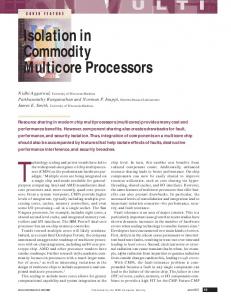
4.4. Performance Summary In Figure 5 we present the RCR numbers for 5 mem-
1
0.9
Relative Cache Effects Ratio
problem. As we pointed out earlier, trace generation was done on an IBM RS/6000 which can issue up to only 4 instructions per cycle; our processor may not find enough ready work in this compiled code. It may be limited by data dependencies and whether our issue queue is large enough to allow the processor to look far enough ahead to discover non-dependent instructions. With in-order issue, our processor model stalls upon encountering instructions for which functional units and queues are busy even when succeeding instructions could have proceeded to idle functional units. Though our instruction issue strategy fails to stress data supply, a more aggressive strategy that can sustain an execution rate of even 4 instructions per cycle would place a lot of demand on the data memory. In absence of unnecessary processor stalls, far fewer clock cycles would be taken to execute each of the programs. Also, if the issue strategy supported speculative execution, additional data references would be generated (e.g. along a wrong path) that do not contribute to computation. Two important metrics of choice are the time it takes to execute a benchmark, reported as Cycle Count, and the L1-L2 bus utilization, reported as Memory Traffic. Other popular metrics of choice are the cache miss and hit ratios. However, with multi-ported non-blocking caches, varying effective memory latencies are seen by the processor depending on the number of outstanding miss requests when an access occurs. Because of this variability in hit and miss latencies, and in latency masking effects due to overlapping of other processor activity, the miss/hit ratios metrics alone do not provide an accurate indication of overall system performance. Since our main focus is to show the effectiveness of the memory system when organized and managed intelligently, we derive a performance measure, the Relative Cache Effects Ratio (RCR), for comparing the various data cache configurations. The RCR of a machine with cache configuration X, is given by:
0.8
0.7
LE-8KB:2R,1W LE-8KB:3R,2W
0.6
LE-16KB:2R,1W ASSIST-(8+1)KB:2R,1W N TS -(8+1)K B :2R ,1W
0.5
0.4
0.3
0.2 APPBT
APPSP
COMPRESS EQNTOTT
FEMC
SPHOT
BENCHMARKS
Figure 5: RCR data for the various configurations. Graph focuses on the portion of processor performance attributable to the cache memory. ory configurations for each of the test programs. For this figure, the focus has been to extract data memory effects of the program runs for effective comparison of performance. The RCR number of a cache memory organization/configuration signifies processor execution performance due to the cache memory, relative to the base 8KB direct-mapped conventional cache with 2 read and 1 write ports (LE8KB:2R1W). The 5 bars shown for each benchmark correspond to RCR numbers for LE-8KB:2R1W; LE8KB:3R2W; LE-16KB:2R1W; ASSIST-(8+1)KB:2R1W; and NTS-(8+1)KB:2R1W, respectively. The first observation from Figure 5 is that increasing the number of memory ports beyond some point, while the cache structure and size remains constant, has effectively no impact on reducing the total execution time. In Figure 5, LE-8KB:3R2W is a direct extension of the base cache which adds two more memory ports, 1R and 1W. Clearly, investing in on-chip logic for two additional memory ports results in no meaningful improvement relative to the base configuration: 0.1% in APPBT, 0% in APPSP, 0.3% in COMPRESS, 0.1% in EQNTOTT, 0.7% in FEMC and 0.4% in SPHOT. The lack of substantial performance improvement in the presence of multiple ports (and nonblocking caching) results from high cache misses and long delayed hitsb in the L1 cache. For a conventional directmapped cache with naive placement and management, this is not surprising. Figure 5 also reveals the performance effects of both i) doubling the cache size; and ii) partitioning the cache space for selective placement and management. LE-16KB is double the size of the base cache. For fair comparison, we assume that both ASSIST-(8+1)KB and NTS-(8+1)KB b. Delayed hit [18], also called a secondary miss in the literature, refers to a miss to a block on which there is another miss request already pending in a non-blocking cache. This access experiences higher latency than a normal hit but does not suffer a full miss penalty.
20
MEMORY TRAFFIC (in million-words)
each will take as much real estate on chip as LE-16KB, even though realistically speaking, they may each require far less chip area. LE-16KB generates RCR improvements from as low as 7% in COMPRESS to as high as 52% in FEMC. The general trend of performance improvement from 8KB to 16KB is consistent with previous studies. As expected, the TBC schemes do fairly well relative to the base cache. NTS-(8+1)KB RCR improves from as low as 7% for COMPRESS to as high as 75% for APPSP while ASSIST-(8+1)KB improves from as low as 3% for EQNTOTT to as high as 56% for APPSP. Considering both TBC schemes and the 16KB direct-mapped cache, the integer programs, COMPRESS and EQNTOTT, appear to be less susceptible to improvement. Unlike the integer codes, the floating-point programs are more structured, often more loop-oriented with lots of data reuse capabilities, and thus benefit more in these simulations from behavior conscious cache organization and management. It is interesting to compare the TBC schemes against LE-16KB. Out of these six programs, NTS-(8+1)KB performs better than LE-16KB in 3 programs (APPBT 30%; APPSP 63%; SPHOT 41%); and the two tie in performance on COMPRESS. Among the two cases that LE16KB outperforms NTS-(8+1)KB (EQNTOTT 7%; FEMC 25%), the relative gain in EQNTOTT is not very significant. ASSIST-(8+1)KB follows a similar performance trend vs. LE-16KB. On average, the TBC schemes show superiority over the conventional direct-mapped schemes across most of the benchmarks. This good performance is well rooted in the functionality of the supporting buffer, which provides dynamic associativity and allows for intelligent data placement. The separation of the reference stream based on data behavior permits T data to reside longer in the direct-mapped unit with minimal disruption. In the NTS Cache, for example, because the buffer is managed differently and possesses a separate replacement queue, temporal and spatial locality can still be extracted from data marked dynamic nontemporal. Figure 6 presents data for the L1-L2 bus traffic, in words transferred from L2 to L1. This graph ignores copyback effects since they are handled through a write-buffer in the background. Again, NTS-(8+1)KB achieves performance competitive with LE-16KB, though the latter is almost double the capacity of the former. Lower memory traffic for the NTS Cache is an indication that the internal state of the L1 cache is well managed, and that useful/ reusable data tend to be resident in the cache more often. This also results in less L1-L2 bus contention. In fact, the performance of the NTS Cache can further improve to yield less traffic and shorter execution cycle counts. Currently, the NTS approach assumes that there is no way of knowing whether a given address location will result in
18
LE-8KB LE -16K B
16
A S S IS T -(8 + 1 )K B
14
N T S -(8 + 1 )K B
12 10 8 6 4 2 0 APPBT
APPSP
COMPRESS
EQNTOTT
FEMC
SPHOT
BENCHMARKS
Figure 6: L1-L2 bus utilization. Memory traffic shown does not include copy-back effects. dynamic temporal or dynamic non-temporal data. The consequence is that every compulsory miss to non-temporal data results in the data being placed in the main cache. The extent to which this data disrupts performance is not easily quantifiable and can be costly. The NTS scheme could certainly be helped by compiler interactions with mechanisms that generate hints as to the temporality of a memory location during compilation. In Figure 6, we also see that in some applications, like EQNTOTT and FEMC, the Assist cache generates noticeably more bus traffic than the base cache. This is due to the fact that these programs have long average temporal reuse distances. For such programs, most cache blocks loaded into the Assist buffer keep streaming through the buffer without ever being loaded into the direct-mapped unit. A more revealing benefit of the TBC approach can be seen in Figure 7, where we compare the performance of 5 cache configurations. These caches could be employed in situations where more die area is available and higher performance is desired. The five configurations are divided into three groups: two TBC designs of size (8+3)KB, two TBC designs of size (16+1)KB, and an LE-32KB cache. For the sake of comparison, we assume that all five of these designs require approximately the same chip area to implement, though in actuality, the (8+3)KB and (16+1)KB designs should be cheaper to implement than the 32KB design. We see from Figure 7 that while LE32KB performs somewhat better in most of the benchmarks, the NTS-(8+3)KB configuration remains highly competitive. In fact, for half of the benchmarks (APPBT, APPSP, and FEMC), NTS-(8+3)KB equals or exceeds the performance of LE-32KB. ASSIST-(8+3)KB generally exhibits performance slightly worse than NTS-(8+3)KB. It is interesting to note that, with the exception of the two integer intensive benchmarks, the (8+3)KB TBC approaches also perform slightly better than the (16+1)KB
6. REFERENCES
70.0
[1] Cycle Count (in Millions)
65.0
60.0
[2]
ASSIST:8K-3K NTS:8K-3K ASSIST:16K-1K
55.0
NTS:16K-1K
[3]
LE:32K
50.0
[4]
45.0
[5]
40.0
35.0 APPBT
APPSP
COMPRESS EQNTOTT
FEMC
SPHOT
[6]
BENCHMARKS
Figure 7: Comparative cycle counts of come cache configurations TBC designs. These results generally favor selective caching over increasing cache size for obtaining higher performance. Of course, a (16+1)KB TBC design will perform better than an (8+1)KB design, but allocating more space to the intelligent buffer can result in higher performance at a similar cost in die area and complexity.
[7] [8] [9] [10]
5. CONCLUSIONS Emerging multi-issue microprocessors need effective data supply to sustain multiple instruction issue and processing per cycle. We have shown in this paper that even ideal non-blocking multi-ported caches fail to be sufficient in and of themselves in supplying data. Instead, more intelligent cache organizations need to be used to more effectively feed the large execution cores of today’s and tomorrow’s microprocessors. In this paper we proposed the use of temporalitybased cache (TBC) organizations as a useful, intelligent caching scheme. Our simulation results show that using a TBC design of size (8+1)KB performs as well as, and in some cases better than, a traditional 16KB direct-mapped cache structure in supplying data. Furthermore, when larger caches can be employed, we find that it is generally more beneficial to allocate some space to a dynamicallyassociative buffer than it is to simply increase the size of the main cache. Our results show that an (8+3)KB TBC design performs as well as, and in some cases better than, a similarly designed (16+1)KB TBC design. Even more impressively, the (8+3)KB TBC design performs almost as well as a 32KB direct-mapped cache, which has almost three times greater storage capacity. Thus, we have shown through cycle-by-cycle simulations that TBC designs can address the data supply problem while incurring comparable cost to the more naive approach of simply increasing the size of the cache.
[11] [12] [13]
[14] [15] [16] [17]
[18] [19]
Y. Patt, “First, Let's Get the Uniprocessor Right,” MicroDesign Resources, Microprocessor Report, August 1996 T.-Y. Yeh and Y. Patt, “Alternative Implementations of Two-Level Adaptive Training Branch Prediction,” Proceedings of ISCA-19, May 1992 S. McFarling, “Combining Branch Predictors,” WRL Technical Note TN-36, Digital Equipment Corp., 1993 T. Conte, K. Menazes, P. Mills, and B. Patel, “Optimization of Instruction Fetch Mechanisms for High Issue Rates,” Proceedings of ISCA-22, June 1995. T.-Y. Yeh, D. Marr, and Y. Patt, “Increasing Instruction Fetch Rate via Multiple Branch Prediction and a Branch Address Cache,” Proceedings of ICS-VII, July, 1993 G.S. Sohi, and M. Franklin, “High-Bandwidth Data Memory Systems for Superscalar Processors,” Proceedings of ASPLOS-IV, April 1991 M. Hill, “A Case for Direct-Mapped Caches,” IEEE Computer 21 (1988) J.L. Hennessy, and D.A. Patterson, Computer Architecture, A Quantitative Approach, Morgan Kaufman Publishers Inc., San Mateo, 1990. K.B. Theobald, H.H.J. Hum, and G.R. Gao, “A Design Framework for Hybrid-Access Caches,” Proceedings of HPCA-I, Jan. 1995, pp. 144-153. S.G. Abraham, R.A. Sugamar, B.R. Rau, and R. Gupta, “Predictability of Load/Store Instruction Latencies,” Proceedings of MICRO-26, Dec 1993 G. Tyson, M. Farrens, J. Matthews, and A.R. Pleszkun, “A Modified Approach to Data Cache Management,” Proceedings of MICRO-28, Dec 1995 J.A. Rivers and E.S. Davidson, “Reducing Conflicts in Direct-Mapped Caches with a Temporality-Based Design,” Proceedings of ICPP, Aug 1996 I pp 154-163 G. Kurpanek, K. Chan, J. Zheng, E. DeLano, and W. Bryg, “PA7200: A PA-RISC Processor with Integrated High Performance MP Bus Interface,” COMPCON Digest of Papers, Feb 1994 E. Rashid et al, “A CMOS RISC CPU with On-Chip Parallel Cache,” ISSCC Digest of Papers, Feb 1994 J-L. Baer and W-H. Wang, “On the Inclusion Properties for Multi-Level Cache Hierarchies,” Proceedings of ISCA-15, May 1988. S. McFarling, “Cache Replacement with Dynamic Exclusion,” Proceedings of ASPLOS-V, Oct 1992 J-D Wellman and E. S. Davidson, “The Resource Conflict Methodology for Early-Stage Design Space Exploration of Superscalar RISC Processors,” Proceedings of ICCD, Oct 1995 E.S. Tam and E.S. Davidson, “Early Design Cycle Timing Simulation of Caches,” Technical Report CSE-TR-31796, University of Michigan, Nov 1996 D. Kroft, “Lockup-Free Instruction Fetch/Prefetch Cache Organization,” Proceedings of ISCA-8, May 1981.