Jun 30, 2008 - lems that arise in reservoir simulation, the most widely used method in ... simulator codes is still the implicit first-order upwind scheme.
On efficient implicit upwind schemes Jostein R. Natvig
Knut–Andreas Lie
June 30, 2008 Abstract Although many advanced methods have been devised for the hyperbolic transport problems that arise in reservoir simulation, the most widely used method in commercial simulators is still the implicit upwind scheme. The robustness, simplicity and stability of this scheme makes it preferable to more sophisticated schemes for real reservoir models with large variations in flow speed and porosity. However, the efficiency of the implicit upwind scheme depends on the ability to solve large systems of nonlinear equations effectively. To advance the solution one time-step, a large nonlinear system needs to be solved. This is a highly non-trivial matter and convergence is not guaranteed for any starting guess. This effectively imposes limitations on the practical magnitude of time-steps as well as on the number of grid blocks that can be handled. In this paper, we present an idea that allows the implicit upwind scheme to become highly efficient. Under mild assumptions, it is possible to compute a reordering of the equations that renders the system of nonlinear equations lower (block) triangular. Thus, the nonlinear system may be solved one (or a few) equations at a time, increasing the efficiency of the implicit upwind scheme by orders of magnitude. Similar ideas can also be used for high-order discontinuous Galerkin discretizations. To demonstrate the power of these ideas, we show results and timings for incompressible and weakly compressible transport in real reservoir models.
Introduction Although decades of research have been focused on efficient and accurate methods for simulating fluid transport in petroleum reservoirs, the most widely used discretization in commercial simulator codes is still the implicit first-order upwind scheme. This indicates that there is a real need for robust schemes that need not be modified when faced with rough coefficients, unstructured, twisted, and degenerate grid geometries characterizing modern reservoir models. High performance of implicit finite-volume methods can only be achieved with efficient solvers for systems of nonlinear equations. Here, we present a method to obtain unsurpassed performance from a standard first-order implicit upwind scheme applied to advective flow, i.e., without gravity or capillary forces; these can be treated by operator splitting if necessary, see (Gmelig Meyling, 1991). Our method is simple to explain. By rearranging the unknowns in the nonlinear system to be aligned with the flow direction, we are able to obtain a nonlinear lowertriangular (block) system that can be solved by one nonlinear Gauss–Seidel iteration. Hence the computational cost per time-step is comparable to simple explicit schemes. To appreciate the potential for such a speedup, recall that to advance the solution one timestep with an implicit method, one needs to solve a large system of equations for the fluid composition in each grid block. Due to the non-convexity of the flow models, the cost of solving the nonlinear system, e.g., with Newton–Raphson’s method, increases quickly with the magnitude of the time-step or the number of grid blocks. Furthermore, for non-convex nonlinear systems, the Newton–Raphson method is not guaranteed to converge. However, each local iteration in the nonlinear Gauss–Seidel iteration is unconditionally stable because the convergence of the underlying nonlinear equation solver is guaranteed. Therefore, the time-steps and model sizes that are possible to use with the implicit upwind scheme will in practice be limited by the efficiency of the nonlinear solver and not by the stability of the discretization. We have previously demonstrated the power of this simple idea for both linear and nonlinear problems: in (Natvig et al., 2007) we computed time-of-flight and stationary tracer flow, whereas in (Natvig and Lie, 2008) we considered incompressible two-phase and three-phase flow. The reordering idea is particularly powerful when applied together with an implicit highorder discontinuous Galerkin scheme, for which the degrees of freedom of neighboring grid blocks are coupled only by the upwind flux and thus can be rearranged to obtain a triangular block system that can be solved efficiently using a Gauss–Seidel type method. In the following we extend the reordering approach to compressible two-phase flow without gravity or capillary forces. The same ideas should also in principle apply to more general compressible multiphase flow models, as long as the models have only positive characteristics. The outline of the paper is as follows. First, we give an overview of the mathematical models and briefly introduce the implicit upwind scheme. Then, we describe how the nonlinear equations and unknowns arising in the finite-volume discretization may be rearranged to obtain a triangular (block) structure. Finally, we present numerical examples to demonstrate the efficiency and utility of our solution method. Mathematical Model Our model problem is incompressible or weakly compressible, immiscible, two-phase flow driven by pressures forces alone. A reasonable mathematical model for this flow must have all fluids flowing in a direction of decreasing pressure, i.e., that each phase velocity vi follows Darcy’s law, vi = −λi K∇p, (1) where K is a positive-definite permeability tensor and the fluid pressure p is common for all phases since we disregard capillary forces. The mobility λi is a positive (scalar) function that models how the flow of phase i is altered by the presence of other phase. The conservation of mass for phase i can be written in terms of the phase saturations u = (u1 , u2 ) as φ
∂ui qi ∂p + ∇ · (fi v) = − φ (cr + ci )ui − fi (u)ci v · ∇p, ∂t ρi ∂t
11th European Conference on the Mathematics of Oil Recovery — Bergen, Norway, 8 - 11 September 2008
(2)
1 ∂ρi where cr = φ1 ∂φ ∂p is the rock compressibility and ci = ρi ∂p is the compressibility of phase i. To obtain an equation for the fluid pressure, we introduce the total velocity v = v1 + v2 and add the conservation equations for the two phases to obtain
φ(cr + u1 c1 + u2 c2 )
q1 q2 ∂p + (c1 v1 + c2 v2 ) · ∇p + ∇ · v = + . ∂t ρ1 ρ2
(3)
To solve the system (1)–(3), we will use a sequential splitting where the pressure equation (3) and transport equation (2) are solved sequentially, each by an implicit scheme. In the following, we tacitly assume that a suitable numerical solution of (1) and (3) is available, given in the form of compressibilities, pressure time-derivatives, and gradients that are constant in each grid block and fluxes that are constant on grid block interfaces. Moreover, we drop the phase subscripts from here on.
Discretization To simplify notation, we introduce the shorthands a = (cr + ci ) ∂p ∂t and b = ci v · ∇p and let un denote the fluid composition at time tn . Assuming that un−1 is given, integrating (2) over a control volume C and approximating the time derivative by a backward difference, we derive the following nonlinear boundary-value problem for un Z ³ φ C
∆t
n
(u − u
n−1
n
n
Z
´
) + φau + f (u )b dx +
Z n
∂C
(f (u )v) · n ds =
C
q dx. ρ
(4)
To get a finite-volume scheme, we partition the domain into grid blocks Ci and approximate u, a, and b by piecewise constant functions with constant values in each grid block. Since we use a piecewise constant approximation of u, the value of f (u) is not well-defined on ∂C. To obtain a consistent discretization, we introduce the upwind numerical flux function. Given inner and outer approximations u+ and u− of u and a normal velocity v · n that is positive when directed outward, the upwind flux fˆ is given by fˆ(u+ , u− ) = v + f (u+ ) + v − f (u− ),
(5)
where v + = max(v · n, 0) and v − = min(v · n, 0). If we let Γij = |∂Ci ∪ ∂Cj | denote the interface area between grid blocks Ci and Cj , the upwind matrix V may be defined by Vii =
X
+ vij Γij ,
− Vij = vij Γij .
(6)
j
The control volume equation (4) may then be written as (I + ∆tA)U n + ∆tφ−1 (B + V )F (U n ) = ∆tφ−1 Q + U n−1 ,
(7)
where I, A, φ, and B are diagonal matrices and U n−1 , U n , F (U n ), and Q are column vectors with one entry for each grid block in the domain. We write (7) compactly as G(U n ) = 0 with G(U n ) = αU n + βF (U n ) − γ,
(8)
where γ is a vector, α is a diagonal matrix, and β is a sparse matrix. The vector-valued function G is non-convex because F is a vector of non-convex functions. Therefore, the standard tool for solving nonlinear systems, the Newton–Raphson method, is not guaranteed to converge when applied to (8). Assume for the moment that β is lower triangular. Then (8) can be written in the more revealing form
α11 α22
U1n β11 U n β21 β22 2 + .. .. . .
f (U1n ) f (U n ) 2 = .. .. . .
γ1 γ2 . .. .
11th European Conference on the Mathematics of Oil Recovery — Bergen, Norway, 8 - 11 September 2008
(9)
Hence, the solution can be computed with the nonlinear equivalent of a single Gauss–Seidel iteration. In each step of this process, a single nonlinear equation is solved using, e.g., the bisection method. In reality, β only has triangular structure in special cases, such as the homogeneous quarter five-spot on a Cartesian grid. However, as we will see in the next section, it is often possible, and quite easy, to find a permutation matrix P that renders P βP T lower (block) triangular. There are big advantages with permuting the equations to triangular structure. Because the bisection method is guaranteed to converge to a solution if it exists, the nonlinear Gauss–Seidel method is guaranteed to converge. This makes the implicit upwind scheme unconditionally stable. Second, with modern root-finding schemes, the convergence rate obtained for each scalar nonlinear equation is close to second order. Furthermore, solving one or a few nonlinear equations at a time is more efficient because we get local control over the iteration. The number of iterations needed for convergence may vary considerably over the domain. Using Newton–Raphson’s method on the whole domain, we have no way to differentiate between ’hard’ and ’easy’ parts of the domain. However, by decomposing the system (9) in a sequence of smaller systems, we may control the number of iterations locally. In fact, we may even change other aspects of the computation locally as well, such as the type of nonlinear solver or the order of the spatial discretization.
Permutation to triangular system To rearrange the equations and unknowns of (8) to obtain a triangular system of nonlinear equations, we seek a (symmetric) permutation P that renders P βP T lower triangular. This permutation may be associated with a sequence p = P [1, . . . , n]T of grid blocks. Since the characteristics of the transport equations (2) are all positive, and the upwind flux approximation preserves this property in a discrete sense, we know that if there is a flux from grid block Ci to grid block Cj , then locally, the solution Uin in Ci depends on the solution Ujn in Cj . Therefore, a necessary condition for P βP T to be lower triangular is that i appears before j in p. However, a sufficient condition for a triangular structure to exist is that globally there are no fluxes from Cj to Ci , either directly or through intermediate grid blocks. To see how we find a suitable sequence p, we form a directed graph G(V, E), where each vertex in V corresponds to a grid block and each directed edge in E corresponds to a positive + flux. In other words, if there is a positive flux vij from Ci to Cj , then there is a directed edge from vertex Vi to vertex Vj in G. Note that there is a one-to-one correspondence between G and the flux field since the sparsity pattern of v + is the adjacency graph of G. In a directed graph, the task of aligning the vertices with the direction of the edges is called a topological sort. This is a classic problem in graph theory, and a topologically sorted sequence of nodes is straightforward to obtain as the post-ordering of the depth-first traversal of the reversed graph, where all the directed edges have been reversed. The post-ordering appends a vertex i to p only when all vertices reachable from i have been added. In other words, grid block Ci is added to the sequence only after all blocks that form the discrete domain of dependence of Ci have been added. However, a topological sort may not exist if there are cycles in G. A cycle (or strongly connected component) is a collection of vertices where each vertex can be reached from any other vertex. The solution to this problem is to collapse all vertices in strongly connected components to a single super-vertex. The occurrence of cycles in G corresponds to irreducible matrix blocks on the diagonal of P βP T . An efficient method to obtain both a topological sequence and the strong components of G is Tarjan’s algorithm (Tarjan, 1972). The parallel to systems of equations is immediate: If the directed graph G is acyclic, the system of equations may be permuted to a lower triangular structure. If there are loops in G, the system may only be permuted to a block-triangular system, where each irreducible diagonal block corresponds to a strongly connected component. Before we proceed, we remark that the idea of rearranging the rows and columns of a square 11th European Conference on the Mathematics of Oil Recovery — Bergen, Norway, 8 - 11 September 2008
matrix to obtain a triangular matrix is well-known in the case of linear equations. If such a permutation exists, the solution of the corresponding linear system is obtained by a simple forward substitution. This method was published in the 70’s by Duff and Reid (1978). The same idea has also been applied to nonlinear systems by Dennis et al. (1994), although not in the context of fluid flow. Wang and Xu (1999) used somewhat similar ideas to compute convectiondominated fluid dynamics. The closest work to ours, however, was done by Reed and Hill (1973) who used a discontinuous Galerkin scheme to solve a neutron transport equation. In the context of porous media flow we refer to Kwok (2007) for an overview of efficient implicit schemes for fluid transport.
Numerical Examples In this section we will compare three different solvers for the nonlinear boundary-value problems (8) arising in each time-step of the implicit upwind method. The first nonlinear solver is a plain implementation of Newton–Raphson’s method with the direct sparse solver from the UMFPACK library (Davis and Duff, 1997), which is generally considered a decent and very robust solver. To get a robust scheme we use 0.5 as initial guess in all iterations, use a relaxation factor of 0.9, and iterate until the nonlinear residual is less than 10−6 . We will call this solver NR–UMFPACK in the following. The performance of the Newton-Raphson method depends on the performance of the linear solver. The second nonlinear solver is the Newton–Raphson method combined with Permuted Forward Substitution (PFS). This linear solver is based on permuting the linear system to lower (block-)triangular form and then using a very efficient forward (block) substitution. For each scalar diagonal element, we compute the solution directly, while for each irreducible diagonal block associated with strongly connected collections of grid blocks, we solve the corresponding linear system using UMFPACK. We call this solver NR–PFS in the following. The third nonlinear solver for (8) is, of course, the Nonlinear Permuted Forward Substitution (NPFS) solver described above. Whereas PFS solves linear equations for each diagonal element in the permuted linear system, NPFS uses nonlinear solvers. In the following examples, we will use Ridder’s method (Press et al., 1992) for the scalar nonlinear equations and the NR– UMFPACK method described above for strongly connected grid blocks. For each nonlinear solver, we report elapsed CPU time per time-step and the average number of iterations per block. Keep in mind that the NPFS solver will use a different number of nonlinear iterations in each grid block. It may even use no iterations if the nonlinear residual is already zero in a grid block. Therefore, the average number of iterations per grid block may sometimes be less than one. In the timings, we exclude time used to calculate the grid-block permutation. These times are reported as a separate number, since one permutation may be used for many time-steps in a sequential splitting scheme. For each simulation, the pressure is computed by a mimetic finite-difference method. For compressible oil, we recompute the pressure and flux fields for each time-step, while for incompressible oil, we do not recompute pressure between time-steps. Because the mimetic solver resembles the mixed finite-element method, we cannot expect flux fields to be acyclic, as discussed in (Natvig and Lie, 2008). However, both the number of cycles and the magnitude of the largest cycle are small, and cycles have little effect on the overall efficiency of the schemes based on permutation of grid blocks. Case 1: The first model is a simple quarter five-spot with unit permeability and porosity. The flow is driven by two rate-controlled wells placed in the corners. We use a Cartesian grid with 100 × 100 × 1 grid blocks, each with dimensions 1 × 1 × 1m. We inject water at a rate of 100 cubic meters per day for 64 days. Both the medium and the water phase are considered incompressible, while for the oil phase we consider two cases: (i) incompressible oil, and (ii) compressible oil with compressibility given by Table 1. The mobilities are quadratic functions of water saturation and the oil to water viscosity ratio is 1.0. 11th European Conference on the Mathematics of Oil Recovery — Bergen, Norway, 8 - 11 September 2008
Table 1: Table of the formation-volume factor Bo [m3 /Sm3 ] as a function of pressure p [bar]. p Bo
27.5890 1.012
82.7371 1.0040
137.8951 0.9960
193.0532 0.9880
248.2113 0.9802
303.3693 0.9724
358.5274 0.9646
386.1064 0.9607
Table 2: Runtimes and average number of nonlinear iterations per block per time-step versus the time-step ∆t for Case 1 with incompressible oil and compressible oil (bottom). ∆t days 2 4 8 16 32 2 4 8 16 32
NR–UMFPACK time (sec) iterations 1.34e-01 13.88 1.43e-01 14.69 1.48e-01 15.12 1.47e-01 15.00 1.48e-01 15.00 1.34e-01 13.84 1.43e-01 14.56 1.46e-01 14.88 1.42e-01 14.50 1.39e-01 14.00
NR–PFS time (sec) iterations 2.45e-02 13.88 2.54e-02 14.69 2.59e-02 15.12 2.53e-02 15.00 2.62e-02 15.00 2.42e-02 13.84 2.52e-02 14.56 2.58e-02 14.88 2.51e-02 14.50 2.44e-02 14.00
NPFS time (sec) iterations 2.48e-03 1.98 2.71e-03 2.27 3.06e-03 2.65 3.41e-03 3.17 3.97e-03 3.84 2.49e-03 1.98 2.71e-03 2.27 3.04e-03 2.65 3.46e-03 3.18 3.98e-03 3.81
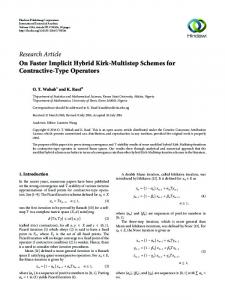
Table 2 reports the elapsed CPU time per time-step for different choices of the time-step. We first observe that NR–PFS is almost an order of magnitude faster than NR–UMFPACK. The better performance of NR–PFS is directly attributed to the efficiency of the PFS linear solver. Secondly, we observe that NPFS is an order of magnitude faster than NR–PFS. This difference can to a large extent be attributed to the iteration count. As pointed out above, NPFS has the ability to vary the number of iterations used from on grid block to the next. It will even use no iterations in grid blocks where the nonlinear residual is zero, as e.g., will be the case in the unswept zone, where the saturation is identically zero. Similarly, in some blocks volume errors coming from the sequential splitting may cause saturations to be outside [0, 1]. NPFS detects this and sets the saturation to either 0 or 1 without any iteration. The Newton–Raphson method, on the other hand, is bound to use the same number of iterations in all grid blocks. The time used to compute the permutation P was 8.0 × 10⁻⁴ seconds. Case 2: The second model is a synthetic faulted reservoir with 72 720 active blocks, with a layered and log-normally distributed permeability field with a ratio of maximum to minimum permeability of 5.3 × 10³ , see Figure 1. We have placed four pressure-controlled wells in this model, two injection wells, I1 and I2, both with bottom-hole pressure 500 bar, and two
Figure 1: Saturation profile after 1 600 days for the synthetic faulted reservoir model with layered lognormal permeability field, two injection wells, I1 and I2, and two production wells, P1 and P2. 11th European Conference on the Mathematics of Oil Recovery — Bergen, Norway, 8 - 11 September 2008
Table 3: Runtimes and average number of nonlinear iterations per block per time-step versus the time-step ∆t for waterflood simulations of Case 2 with incompressible oil (top) and compressible oil (bottom). ∆t days 100 200 400 800 100 200 400 800
NR–UMFPACK time (sec) iterations 6.66e+01 14.38 6.38e+01 14.62 5.76e+01 14.75 5.02e+01 14.50 7.27e+01 13.81 6.54e+01 14.50 6.68e+01 14.25 5.63e+01 14.50
NR–PFS time (sec) iterations 1.25e+01 14.38 1.27e+01 14.62 1.28e+01 14.75 9.96e+00 11.50 1.18e+01 13.81 1.24e+01 14.50 1.22e+01 14.25 1.24e+01 14.50
NPFS time (sec) iterations 4.35e-02 2.00 4.58e-02 2.33 5.42e-02 2.79 6.22e-02 3.26 6.55e-02 1.84 6.62e-02 2.15 7.21e-02 2.66 9.15e-02 3.24
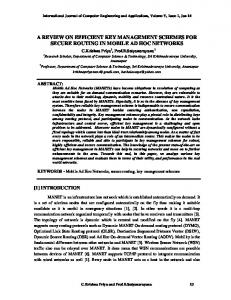
Figure 2: Water saturation in the Johansen formation from the North Sea after 100 000 days of water injection.
production wells, P1 and P2, with bottom-hole pressure 250 and 300 bar, respectively. For this case, the nonlinear system (8) will not be in (block) triangular form. Furthermore, due to the heterogeneity of the model, we cannot expect the flux fields to be acyclic. However, in the computations reported below, the number of strongly connected components was on average 20, the number of grid blocks in strongly connected components was altogether 942, and the largest component involved contained 823 grid blocks. The time used to compute the permutation P was 1.1 × 10⁻² seconds. Table 3 reports the elapsed CPU time per time-step for a simulation of 1600 days of water flooding a reservoir initially filled with incompressible oil. Again, there is an order of magnitude difference in runtimes both between NR–UMFPACK and NR–PFS and between NR–PFS and NPFS. Table 3 also reports the elapsed CPU times when the oil is assumed compressible oil. As we see, the runtimes do not change significantly for weakly compressible fluids. Case 3: The third model is a geological model of a North Sea sandstone formation, with one large fault and several smaller ones, see Figure 2. The permeability and porosity fields are quite smooth with jumps between the layers. The ratio of largest to smallest permeability is 8.8 × 10⁴ . The grid, however, is quite rough with 27 437 blocks, many of which are twisted and pinched. The ratio of largest to smallest grid block is roughly 4 × 10³ and the ratio of largest to smallest face areas is 106 . The model was originally used to study the feasibility of CO2 deposition, but here we pre11th European Conference on the Mathematics of Oil Recovery — Bergen, Norway, 8 - 11 September 2008
Table 4: Runtimes and average number of nonlinear iterations per block per time-step versus the time-step ∆t for waterflood simulations of the Johansen formation from the North Sea with incompressible oil (top) and compressible oil (bottom). ∆t days(!) 12 500 25 000 50 000 100 000 12 500 25 000 50 000 100 000
NR–UMFPACK time (sec) iterations 2.26e+00 12.69 2.35e+00 12.62 2.38e+00 13.25 2.50e+00 13.50 2.19e+00 12.69 2.02e+00 12.75 2.09e+00 13.25 2.20e+00 14.00
NR–PFS time (sec) iterations 3.28e-01 12.69 3.32e-01 12.62 3.46e-01 13.25 3.49e-01 13.50 3.91e-01 12.69 3.86e-01 12.75 3.90e-01 13.25 4.11e-01 14.00
NPFS time (sec) iterations 4.44e-02 0.93 4.73e-02 1.10 4.16e-02 1.41 4.21e-02 1.99 5.82e-02 1.33 6.07e-02 1.48 6.16e-02 1.79 6.39e-02 2.38
Figure 3: Number of iterations for each block in the Johansen model for a typical time-step. tend that it is a petroleum reservoir. The reservoir covers roughly 50 × 50 kilometers and 1 kilometer in the vertical direction and the volumes and time scales involved are, of course, totally unrealistic, but the heterogeneity and geometrical complexity are representative for a real reservoir. In the model, we place one producer in the center near the large fault, and three injectors in different sectors. All wells are vertical, pressure-controlled wells with bottom-hole pressures of 300 bar in the producer and 700 bar in the injectors. We observe that the number of strongly connected components in the flux fields was on average 77.4, the number of grid blocks in strongly connected components was around 780, and the largest component involved contained 380 grid blocks. The time used to compute the permutation P was 3.6 × 10⁻³ seconds. Table 4 confirms the trends seen in the two previous cases that NPFS is about one order of magnitude faster than NR–PFS, which again is about one order of magnitude faster than NR– UMFPACK. We also note the low iteration count for NPFS. To support the explanation given in Case 1, Figure 3 shows the number of iterations in each grid block for a typical time-step after the injection fronts have extended into the reservoir. The figure shows that no iterations are performed in the unswept zone and that the maximum number of iterations appears in the well blocks and in regions behind the injection fronts.
Concluding Remarks We have shown that the solution of purely advective flow can be made orders of magnitude faster by utilising the flow directions of the flux field (as is done in a streamline method) to 11th European Conference on the Mathematics of Oil Recovery — Bergen, Norway, 8 - 11 September 2008
rearrange the discrete equations into a lower (block) triangular form that can be solved very efficiently using a single nonlinear Gauss–Seidel iteration. We have previously shown (Natvig and Lie, 2008) that this idea may be used to develop implicit methods that scale linearly with model size. Herein, the focus has been on extending the methodology to compressible flow and on investigating the robustness versus that of a standard Newton–Raphson method. Although the results show that the method is highly efficient, one may object that gravity and capillary forces cannot be included directly in the method, as this would violate the underlying assumption of unidirectional flow. However, gravity and capillary forces can easily be treated using operator splitting, as has been done successfully with streamline methods for the last 10–20 years. Moreover, the ideas presented here can readily be extended to more complex flow models and higher-order spatial discretizations, as demonstrated in (Natvig and Lie, 2008). In summary, we find the results very promising and believe that the method has a significant potential for practical applications. Acknowledgements: The research was funded by the Research Council of Norway through grant no. 186935/I30. We thank B. Skaflestad and H.M. Nilsen for useful discussions and help with developing the pressure solver used in all the experiments.
References Davis, T.A. and Duff, I.S. [1997] UMFPACK: An unsymmetric-pattern multifrontal method for sparse LU factorization. SIAM J. Matrix Anal. Appl., 18(1), 140–158. Dennis, Jr., J.E., Mart´ınez, J.M., and Zhang, X. [1994] Triangular decomposition methods for solving reducible nonlinear systems of equations. SIAM J. Optim., 4(2), 358–382. Duff, I.S. and Reid, J.K. [1978] An implementation of Tarjan’s algorithm for the block triangularization of a matrix. ACM Trans. Math. Software, 4(2), 137–147. Gmelig Meyling, R.H.J. [1991] Numerical methods for solving the nonlinear hyperbolic equations of porous media flow. In: Third International Conference on Hyperbolic Problems, Vol. I, II (Uppsala, 1990). Studentlitteratur, Lund, 503–517. Kwok, F. [2007] Scalable linear and nonlinear algorithms for multiphase flow in porous media. Natvig, J.R. and Lie, K.A. [2008] Fast computation of multiphase flow in porous medis by implicit discontinuous Galerkin schemes with optimal ordering of elements. J. Comput. Phys. Natvig, J.R., Lie, K.A., Eikemo, B., and Berre, I. [2007] A discontinuous Galerkin method for computing single-phase flow in porous media. Adv. Water Resour., 30(12), 2424–2438. Press, W.H., Teukolsky, S.A., Vetterling, W.T., and Flannery, B.P. [1992] Numerical recipes in C. Cambridge University Press, Cambridge, second edition. The art of scientific computing. Reed, W.H. and Hill, T.R. [1973] Triangular mesh methods for the neutron transport equation. (LA-UR-73-479). Tarjan, R. [1972] Depth-first search and linear graph algorithms. SIAM J. Comput., 1(2), 146– 160. Wang, F. and Xu, J. [1999] A crosswind block iterative method for convection-dominated problems. SIAM J. Sci. Comput., 21(2), 620–645.
11th European Conference on the Mathematics of Oil Recovery — Bergen, Norway, 8 - 11 September 2008