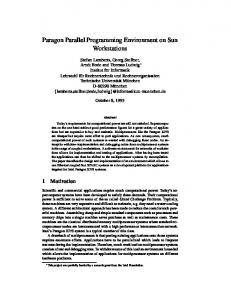
On Exploiting Declarative Programming and Parallel Execution in Computer Based Real-time Systems Bengt Lennartsson (Email: BenLenQCarlstedtse) Nahid Shahmehri (Email: NahShaQCarlstedt.se) Staffan Bonnier (Email:
[email protected]) Carlstedt Elektronik AB, Industrivagen 55, S-433 61 PARTILLE, Sweden. Phone: ( 4 6 ) 31 - 26 21 80 Fax: (+46) 31 - 26 21 81 is just to give a summary of what all these people have developed, and to illustrate by a very simple example how H and rp8601 can be used in a sequence control application. All the persons who have contributed: the employees at the company, its Scientific Advisory Group, and others, are hereby deeply acknowledged.
Abstract This paper presents experiences from modelling real-time applications in the declarative functional language H developed hand-in-hand with a novel rp8401 parallel graph reduction architecture, both designed with the requirements from real-time embedded systems in mind. In rp8601 the analog and digital interactions with the environment have been designed into the chips and into the language, and so have mechanisms to handle time constraints. Traditionally declarative programming means that the programmer need not be aware of the processor operations. Instead he can focus on the abstract relations between the input and the output streams. The specific real-time requirements have normally not been taken into account in the declarative view. Our conclusion is that declarative functional programming is a viable techniquefor the development of complex software for embedded real-time systems. However, considerable efforts have to be spent on educating and training the application programmers in the new programming paradigm.
1
The rp8601 project is aiming at exploiting the combination of two maturing and well researched ideas: massive parallelism and declarative programming. Parallelism gives better system performance as the total capacity available is equal to the power of each processing element multiplied by the number of such elements. The objective for a declarative language is increased programmer productivity and higher program quality. The programmer can directly specify the operationsin terms of the rules and the constraints the computation has to obey, rather than as all the small steps for the operations and data movements. However, previous attempts to exploit parallelism have, in the general case, failed due to the difficulty to efficiently distribute the total computationover all the available parallel processors. In order to distribute the computation over the parallel hardware, a large amount of manual control of the program execution and of the load balancing have been needed. The industrial use of declarative languages has so far been rather limited, mainly because of performance problems due to the mismatch between the declarative languages and the von Neumann hardware architecture. Hence the increased performance by parallel execution has been paid forby increased programming efforts. The reduced programming effort by means of
Background and acknowledgement This paper presents an overview of a development project at Carlstedt Elektronik AB. The comerstones in this project are the language H and the pamllel graph reduction architecture rp8601, both originating from Gunnar Carlstedt. As early as 1986he presented his EuroMicro paper A Languagefor Behavior, Structure and Geometry [l].The last sentence in this paper reads: The language will be called “H”. Since then many persons have been involved in transforming Gunnar Carlstedt’s visionary ideas into a working system. The role of the authors of this paper
131
0-8186-5715494$04.000 1994 IEEE
Introduction
declarative languages has resulted in the penalty of relatively slow execution. The combinationof the declarative language H and the specially &signed parallel hardware architecture, rp8601, gives all the benefits mentioned above, but without the extra costs and penalties! Instead there are even more benefits as H and rp8601 smngly support each other.
1.1
Consequences of the rp8601 architecture rp86Olsystemsare built from two basic oomponent
1.2
types: the computememory and rheport memory. The computememorycorresponds to the processor and its local memory in a traditional multipmcesor system. Tbe port memory plays therole of an U 0processortogether with its local programmemory and Yo buffers.
Implicationsfrom the declarative programming language H
The progntmminglanguage H will in the fmt product generationbe a functionallanguage. Later on logic programming features like logical variables and unification may be added if required. The execution of the purely functional language H is free from side-effects. A symbol denoting a variable can not change from one value to another during the execution of a program, i.e. the “variables” in H do not “Vary” as they can do in imperative languages. A symbol in H is defined by an expfession, and during execution this expression is reduced until only one single canonid value remains. Thus a symbol stands for a constant value, perhaps not yet known. llanks to hedom fiom side-effects, a reference to a value can always be replaced by the value itself. The execution mechanism employed for functionalpgrams is called reduction. The result will be the same independently of the order in which the reductions are d. They can be made fully in parallel, and no extra infomation from the programmer is needed. A general presentation of the princiiles of declarative programs can be found in [2] and [3]. The references [41and [SI give an introductionto reduction and to the implementation of functionai languages in general. Hence, if there were any hardware architectureable to reduce all reducible subexpressions in parallel, it would exploit aU the inherent parallelism available in tbe problem. The architecture of rp8601 is based on
Flgurp 1 One single system composed of compute memories, C, and port memories, P.
Tbe comparison with traditional systems is misleading, bowever. ’Iberp8601 is based on associative, ar content addressable, memory.A specific physical memory location has no p e ” t l y assigned address or label. The only means available to address a location is by its anrent contents. Both the compute memory and the port memory components irre based onthesame” forasouatl * ‘veaddressing. The associarive memory has the general property of strongly supporting global search operations. It is also very powerful during execution of H programs, and it makes the garbage collection extremely efficient. Assume that an H variable x is referend from many places in the program,that is, the value of x is needed for the reductim of many (sub-)expressions. when the value of x bas reduced to canonkal form, this value will be braadcast togeUm with the symbol x, andall refelenas to xcanbefeplacedby this canonical value in one single memory operation! 13
thisidea
Thus the declarative nature of the H language has two major implications: 1. The H programmer need not use his time to specify in which order different operations are performed asmust tbe programmer in an imperativelanguage. 2. On execution of an H progfam, parallel graph re duuion hardware can directly be fully exploited withwt any extra effort or infomarim from the Programmer. The graph Feduction strategy used for execution of H programs enables sharing of subgraphs, so reductions do not have to be repeated when the result is needed at different ‘’places9’in the total computation.
Conceptual architectureversus engineeringdesign decisions
Many engineering trade-off decisioos are about granularity. What word length is most appropriate? Should the instruction set contain complex composite operationsar be based on a RISCphilosophy?In most such situations there are extreme points, and the optimal design, based on experience and engineering howledge, is samewhere m betweea. In rp8601 these are alsomany such trade-off decisions, and it is veay likely gome of them will change as more experiencewill be gatbered. Some examples: Wemory word size”: Each storage unit holds a “closure”, ar a graph node, consisting of four ‘Wue fields”,a colltext field, a closure typefield, an at132
infinite data structures m a y create pblems. So even here some middle way has to be taken.
tribute field, and an identifier. The four ‘‘value fields”, the context field, and the closure identifier field each has 32 bits “data” + a 6 bit tag field + error detectiodcomtion bits. So each storage unit has space for 192 bits, 24 bytes. However, due to the extra type and status information in the tag and attribute fields, and to the more compact representation of functions and operators, one storage unit of rp8601, one closure, holds more information than do 24 bytes in a traditional system. Size of a compute memory module: In the compute memory each storage unit holding a 24 byte c b sure, as described above, is capable of simple operations like replacing an identifier by a value. However, each storage unit does not have the full power for arithmetic and logical operations. It would be possible to give this power to each storage unit, but that would mean a considerablewaste of silicon area. As only a small fraction of the nodes of the graph, or the closures in the memory, have the information needed for immediate reduction, there need not be reduction power available for all closures at the same time. On the other hand only one processing unit per system would mean that the possibility for parallel operations would not be exploited. So, a natural solution is to have “processors”available for a suitable fraction of the storage units. Currently a Compute Memory has 5 12 storage units (closures)and one core cell containing a reduction unit and a numeric unit. A port memory module has in the current plan the same storage capacity, 512x24 bytes = 12 U, plus type and status information, as the compute memory has. Scheduling strategy: When processing power is the bottleneck, demand driven evaluafion’ is a natural strategy. Demand driven means that a computation is postponed until the result is really needed. In a system having a surplus of processors data driven evaluation’ may be more appropriate. If you evaluate an expression as soon as the required values are available, you are applying data driven evaluation. Fully demand driven evaluation is one of the extreme points. Processing power is saved and infinite data streams can be used. At the other extreme point, fully data driven, computable data is always available in case it is needed. Demand driven evaluation and real-time requirements do not match very well. A fully data driven strategy and
2
Real-time constraints vs functional pWFa”ing
The rp8601architecture and the H language have been designed with embedded real-time applications in mind. The most important characteristics for this class of applications are: 1. Unconventional Y O the computer system and its physical environment are interacting via digital and analog signals. 2. The interaction between computer system and its environmentmust take place at prescribedpints in time (at regular intervals, within a certain time interval after an extemaI event, or at a certain value of the external “real time”). 3. The embedded systems are generally running “for ever” rather than terminating after having computed a result as a function of the input. 4. The computation in an embedded application often contains a model of the dynamic physical environment, and such models have in general a periodically updated state as the main component. The properties 1-4 above are generally not associated with functional programs. In our case the unconventional YO is taken care of by the powerful rp8601 port chips. This will, however, not be discussed any further in this paper. In the following it will be illustrated by means of an example how the aspects2-4 are handled. Other declarative languages taking some of the real-timerequirements into account are Strand [81 and Erlang [9].The concurrency in Strand and Erlang are of the type “interacting sequentialprocesses” while H has much finer granularity in its parallelism.
3 The H language The language H is intended for both applications and systems programming, and is divided into two sublanguages: HUF: The Functionaldefinition sublanguage. Hus: The System description sublanguage. The general idea is that most application programming can be done using only the graphical system description language. Thus it is necessary that a large and powerful library of predefinedprimitive functions and boxes are available. 3.1 The functional definition sublanguage HUFallows functions to be defined in a way similar to traditional functional languages (such as ML, Haskell etc.) [6-71. Tbe language HUFprovides:
l.Oihe.r names for demand driven are: lazy cvaluation, b a c h r d chaining, or conservative evaluation. Instead of a b driven the terms: eapcr ” evaluation..soeculative . evaluatim,orforward chaining are used.
133
b) Waiting car detected by the NS sensors: (1) turn EW lights to G+Y for 2 s (still R on NS); (2) t u ” S lights to R+Y andEW to R for2 s; (3) turn NS lights to G for 10 s (still R on EW); (4) turn NS lights to G+Y for2 s (still R on EW); (5) turn NS lights to Rand EW to R+Y for 2 s; (6)turn EWlights to G for 15 s (still R on NS); (7)cbeck NS s e w n again. The sensors are thus checked for the presence or absenceof cars on the NS road at the end of each cycle.
A module system, admitting selective exportation
of dehed objects (such as types and functions). This enables the definition of abstract data types. A type checking system, allowing both polymorphism and subtyping. The latter implies a more expressive language of types than the one used in traditio~~I Hindley-Milnersystems [5]. pa#em matching as amfor discriminatingarguments m function applications.
3.2 The system description sublanguage This sublanguage HUS allows the user to express the relations between input and output streams in a
4.2
graphical notation.The diagrams aremade f ” basic building blocks interconnected by streams. At this level the flow between pats is specified and analysed. Tbe language H u provides: ~ A graphical and a textual syntax. The language is, however, primarily graphical. A module system, allowing diagrams to be enclosed in boxes. These boxes may themselves be used as (non-primitive) building blocks. A type system, ensuring that the flow in diagrams will not be blocked by incompatible connections.
4
An HUS program umsists of a number of building blocks interconnectedby streams. A stream is considered an infinite seqmwe (list) of values. A building block consumes its input streums and produces its output streams. A stream is represented as an arrow. When attached to a block, its direction indicates whether it represents an input or an output stream of the block. A box descnptwn is an encapsulation of an HUs program. Thus box descriptions serve as modules of the language. Input and output c o ~ e c t o f sof the program become input and output sockets of the description (“valleys” and “hills” on its border respectively). The input and output CoRnectOrs of a program Serve as the interface between the program and the extemalworld. To defme aprogram we need three kinds of blocks’, see Figure 3.
A traffic light controller example
Let us now illustrate how H may be used for programminga trafficlight controller. Cablesconnect the real-timeenvironment to threeports of the computer system. ’Ibe ports are: the sensor part, the NS-Light port and the EW-Light port.
4.1 The problem spedfcation Tbe behaviour of the traffic lights can be described by the two cycles below. The NS sensors are checked at certain times. Depending on the result one of the two following sequences of behaviourswill be initiated,(G. Y. and R are used to denote the colours: green, yellow, and red,respectively).
Figure 2
The top level Hm program
An input connector
Figure 3
An output connector
A box description
with one input stream, two output streams, and two parameters. The three kinds of elementary building
blocks Of HuS In order to put a box description into use, an in-
stance of the description must be created. Such an instance is simply called a box. It is obtained by instantiating the formal parameters of the description and by connecting its sockets.There are two ways of establishing tbe latter: By connecting the input and output sockets to ports. The program of the box description is then made to interrsd directly with external devices connected to the ports. By connecting the input and output sockets to streams. The box may then be used as a building block of a larger program.
Traffic lights controlled by rp860l.
a) No waiting car detected by the NS sensors: (1) keep E W lights G, and NS R, for another 15 s; (2) check NS sensors again.
1. The ~ o c e o f symbob h k very preliminuy. It will d m g e aa the language evolves. .ndthe maucte graphical syntax may be med to particular application e m s .
134
Fl
The top-level program is encapsulated in one single box description, Figure 4. The sensor state (car or NoCar) is the input on the top. The NS light (G, GY, R, or RY) is output at the bottom, left, and the EW light (G, GY, R, or RY) at the bottom, right.
f
A function f with five (positional) parameters PI,p2, p3,p4, p 5 , where p3, p4 and p5 are the three streams, from left to right, entering the box at the top.
ci3
implementation of the trafficcontrol is illustrated in Figure 7, where c 1 and c2 are the cycles defined as: c l = [ (15, (G,R)) I ;
Top level program.
The box trafficcontrol defines the relation between the input stream and the output streams. There is a notion of “real” time; the green EW and the red NS light shall be maintained for 15 s, for instance. In the following it will be shown how these non-functional properties can be modelled in the functional framework. To model real-time we need two more symbols in our graphical language, see Figure 5.
a A clock tick generator; time T between ticks.
C2 = [ ( 2 ,
(GYrR)), (2, (R,RY))r
(10, (R,G)), ( 2 , (R,GY)), (2, (RY,R)), (15, (G,R)) I ;
I
1
I
b A stream controlled input connector.
Figure 5 Two more elementary symbols. The clock tick generator has no input. After initialisation it emits a token, a tick, every T seconds. The stream controlled input is a symbol making the request for input explicit at the system description level’. After initialisation the input connector will convey a value from the environment to the executing program every time a token arrives at the arrow of the input connector symbol in Figure 5 b. Thefunctionbox serves as an interface between the graphical Hus and the textual HuF. A function box description, having n parameters and m input sockets, must be defined in terms of a function taking n+m arguments, the last m of which are streams. In HUFthere must be afinction type definition: f
7-
Figure 6
trafficcontrol
Figure 4
Pl P2
Figure 7 The content of trafficcontrol. The definition is partly in the graphical Hus language and , . partly in the purely functional,H
Each cycle consists of a number of Phases.Thus a cycle is defined as a list of phases: type Cycle = [ Phase 1 ; A Phase consists of a pair of time duration and
colour indication. The colour indication is itself a pair which indicates the colour of the traffic lights on the EW and NS roads for the duration defined by the fust element of the phase. type TimeDuration = Nat; type Phase = (TimeDuration, (Colour,Colour))
:: tpl->tp2->tp3->tp4->tpS->tr
(where t p l denotes the type of p l etc.) followed by thefunction rules defining how the output stream r can be computed from the parameters p 1 and p2 and the three input streams; see Figure 6. A straight forward request-driven “declarative”
;
The diagram is itself composed f ” instances of three different box descriptions, namely: cycleSelector, splitCycle, and 1ightTimer.
4.3 Implementationof the details At initialisation the tokens GetInput and GetPhase will be present on their streams, and the clock ticks are emitted every second from then on. Car or NoCar will be sent from the input connector and, depending on which token is present, the fmt tuple of c i
1. The general model for the ports in H is that there is a request streum sent to the port, and a response streum from the port to the executing program. It may often be the case, however, hat the request stream is invisible at the system desaihon level; its role is confined to the low level configurationof the port.
135
or c2 will be transferred selected by the cycleselector. In Hm the type definitions for clock ticks,
letThrough ((phase:cycle):cycles) (GetPhase:gphase)= phase : (1etThrough (cyc1e:cycles) gphase); letThrough ([]:cycles) (GetPhase:gphase)
light colours, car sensors and the definition of the function cycleselectorare as below:
--
data ClockTick = Tick; data Colour = G I Y I R I RY I GY; data Carsensor = Car I NoCar;
GetInput: (1etThrough cycles gphase); Box pass (==) GetInput passestheinputvalues which are equal to GetInput and filters away other values. Box pass ( / = ) GetInput performs
cycleBelector :: t(CarBoneor, Cycle)] -> Btroam CarBonaor -> Stream Cycle;
cycleSelector behaviour (sensor:sensors)
the opposite filming.
car).
paaa :: (PhaaePlue -> PhaeePlue -> Bool) - > RequeatInput -> Btream PhaeePlue - > Btream PhaeePlua; pass p comp (phasep:cycle)= if (p phasep comp) then (phasep : (pass p cycle)) else (pass p cycle);
The EW and the NS lights defined in the tuple will be sent to the output connectors,and after the prescribed time interval a new phase will be quested by means of a new GetPhase token. This will proceed until there are no more phases in the cycle. Then new sensor information will be asked for, and a new cycle will be selected dqxmding on Car or NoCar. Thisinfonnal explanation illustrates the modelling of the application at the graphical system description
Figure 9
-
(assoc [ I behaviour sensor): (cycleSelectorbehaviour sensors);
The predefined assoc function returns the cycle which corresponds to the car sensor value (Car or No-
PhasePlus
f8t :: (a, b) -> a; fst (x, -1 = x; end I : (a, b) -> bi
RequestInput
Figure 8
Definition of the box split.
The '@' before a function name in a function box, see Figure 9, means that the function is from the element of the input streams to the element of the output stream rather than on the whole streams. This is known in the functional programming community as the map function. The two functions f st and snd from Figure 9 are defined as:
level Hus.
snd
(-I
Y) = Y;
Definition of the box splitcycle.
The splitcycle box is m m complex than the previously discussed cycleselectorfunction box. 'Ihisbox ca"unicates with the box 1ightTimer.It sends one Phase at a time on arrival of a GetPhase request When the last phase is consumed it sends a GetInput request to the input COM~C~OZS. This is done by defining the two function boxes letThrough and pass. In HUF the type defmitions for GetInput and GetPhaseare:
ClockTic
NS-Light
EW-Light
Figure 10 Definition of the box 1ightTimer. The delay function takes a time d d o n t and a s t " of clock ticks as input and produces a GetPhase when t clock ticks has passed. This is achieved by transferring into an interndl state. Tbe technique can be studied in detail in, for example, [2].
data Requestphase = GetPhase; data RequestInput = GetInput; type PhasePlus = Phase I RequestInput; 1etThrough:: Btream Cycle -> Stream RequeetPhaee - > Btream PhaeePlua;
136
power of the higher order functions in H, the function blocks themselves can be implemented much faster and safer than in the imperative way. The H language and the programming environment will make the interconnecting work safer and faster. H and rp8601 are now being tested in a full scale AutomaticGuided Vehicle application. The experience so far is that the principles shown in the traffic light example really scale up. Comparisons between Eirlang and imperative programming in telecommunication applications within Ericsson show similar results.
delay :: Stream TimeDuration - > Stream ClockTick - > Stream RequeetPhaee;
delay ((duration+l):durations) (Tick: ticks) = delay (duration : durations) ticks; delay (0:durations) (Tick:ticks) = GetPhase: (delay durations ticks);
4.4 Comments on the implementation One property of this implementation of traf ficControl is that tokens occur on the streams only when requested by the receivers. Where the ordering of events or of computations is essential, the control has been made visible and explicit by means of the two request streams in Figure 7. The duration of the phases is controlled by the ticks from the clock tick generator. It is assumed that the computation in the boxes will be done “immediately” when the required input tokens arrive. The strategy is similar to what is called resource adequate systems in 1103. The assumption that sufficient processing power is available is quite realistic in the rp8601 case. The structure of the algorithm, Figure 7, together with the surplus of processing capacity, guarantees that the intemal streams will not be flooded, and that the phase durations will be as required.
5
6
Futurework
The development of H and rp8601 will proceed, and they will be introduced to the real-time systems market. By then, the language as well as the development support environment and the developmentmethodology will have evolved further. We will encourage studiesto measure how programmerproductivity may be improved by the use of a declarative language. As rp8601 is aiming at removing the current penalty of poor runtime efficiency, order(s) of magnitude in increased productivity by means of expressive declmtive languages will mean a lot.
References [ 11 G. Carlstedt: A language for behavior, structure and geometry. P m e d n g s Eurom‘cro ’86.Venice, Italy, September 15-18, 1986. p ~567-580. . [2] H. Abelson, G. J. Sussman: Structure and Interpretation of ComputerProgram. The MIT Press. The MIT Electrical Engineering and Compter Science Series. 1989. ISBN 0-262-01077-1. [3] A. J. Field, P. G. Harrison: Functiml Progmmming. AddisonWesley Publishing Company. International Computer Science Series. Reading 1988. ISBN 0-201-19249-7. [4] R. F%meijer, M. van Eekelen: Functiml Programming and Parallel Graph Rewriting. Addison-Wesley Publishing Company. International Computer Science Series. Padstow, Cornwall, UK, 1993. ISBN 0-201-41663-8. [5] S . L. Peyton Jones: The Implementation of Functional Programming Languages. Rentice-Hall International Series in Comp t e r Science. New York, June 90.ISBN 0-13-453333-X. [6] A. Wikstrom: Functi~malProgmmming Using Standand ML Rentice-Hall International Series in Computer Science. Camhidge, 1987. ISBN 0-13-331968-7. [7] P. Hudak et.al. (4s): Report on the Pmgramming Language Haskell - A Non-strict, Purely Functional Language. Version 1.2. March 1992. ACM SigPlan Notices. 27. (5). pp.1-164. [8] 1. Foster, S. Taylor: Strand - New Concepts in Parallel Programming. Rentice-Hall, Inc. New Jersey 1990. ISBN @13850587-X. [9] J. Armstrong, R. Viiding, M. Williams: Concurwnt Ptugmmming in ERDWG. Rentice-Hall International. Trowbridge, Wilshire, UK, 1993. ISBN 0-13-285792-8. [lo] H. W. Lawson:Cy-Clone - An Approachto the Engineering of Resource Adequate Real-time Systems. Real-TimeSystems. Vol4. No 1. (March 1992). [ l l ] H. Elmqvist:AnObjectandData-FlowBasedVisualLanguage for Process Control. Proceedings of Instrument Society of America (IW2-C&), Toronto, Canada, Apnl28-30,1992.
Conclusions
This very simple example illusmites the principles for module definition and interconnection in H. Once a module has been defined and implemented, it can serve as an off-the-shelf reusable component. Such building blocks can be defined at any level of complexity; they can be built by interconnecting simpler boxes by means of streams, or they can be defined in terms of higher order functions. The combinationof the graphical HUSand HUFhas turned out to be very useful and expressivein different domains, not only for the simple sequence control problem used as an illustration in this paper. High speed signal processing and direct digital control are two other target areas. So far our experience is that the domain of real-time applications can be added to the areas where a declarative language has turned out to be superior to imperative languages. The power of graphical tools for building applications from module libraries has been demonstrated by the AMPL language at ABB. and by the SattLine system from SattContml [ l l ] in industrial automation. After some hundred library functions have been defmed, almost all application development can be done in terms of connecting existing function blocks. Due to the freedom from side-effects and to the 137