IEEE SIGNAL PROCESSING LETTERS, VOL. 6, NO. 3, MARCH 1999
61
On Fast Algorithms for Computing the Inverse Modified Discrete Cosine Transform Yun-Hui Fan, Vijay K. Madisetti, Member, IEEE, and Russell M. Mersereau, Fellow, IEEE
Abstract—Two new fast algorithms for computing the inverse modified discrete cosine transform (IMDCT) as used in the adaptive spectral entropy coder (ASPEC) [2] are proposed. A fixed-point error analysis is presented to determine the number of significant bits required for fixed-point implementations. Index Terms—Audio coding, discrete cosine transform, discrete Hartley transform, discrete transform, error analysis, quantization, signal reconstruction.
factor of two and an inverse transform. Direct implementation additions and multiplications. requires The first algorithm (IMDCT-I) is a variation of the algorithm by Lee in [4]. The derivation begins with multiplying both , which is sides of (1) by always nonzero for integer . After some manipulation with the equation and separation of the output into two halves, we get a pair of equations as follows.
I. INTRODUCTION
T
HE MODIFIED discrete cosine transform (MDCT) is part of the time domain aliasing cancellation (TDAC) transform that appeared in [6]. The ASPEC coder utilizes the oddly stacked TDAC transform. We will consider the transform of lengths of power of two. In important practical applications, e.g., playback media, the computational speed of a decoder is of more importance than the encoder, and a majority of the computational resources is consumed in the transform computation. Therefore, we will present two fast IMDCT algorithms and, more importantly, a fixed-point error evaluation. It will be shown in Section II that while both algorithms are FFT-like, many differences do exist. Due to a slight difference in the decomposition processes, the two algorithms possess very different characteristics—one requires fewer operations and less memory but is unsuitable for fixedpoint implementation, while the other requires relatively more operations and memory, but is more suitable for fixed-point implementation. In Section III, an experimental evaluation of fixed-point errors of the latter algorithm will be presented. II. IMDCT ALGORITHMS The IMDCT discussed in this article is defined by the equation [2] (1) and . is a where positive integer. The IMDCT combines an interpolation by a Manuscript received February 18, 1997. This work was supported by the U.S. Air Force under Contract F33615-94C-1493 RASSP Technology Base Program, 1994–1997, to GTRC/DSP Laboratory. The associate editor coordinating the review of this manuscript and approving it for publication was Prof. A. Tewfik. The authors are with the Center for Signal and Image Processing, Electrical and Computer Engineering, Georgia Institute of Technology, Atlanta, GA 30332-0250 USA (e-mail:
[email protected]). Publisher Item Identifier S 1070-9908(99)01791-5.
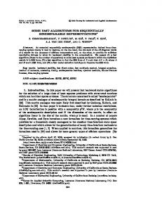
for where . Further decomposition requires an additional manipulation similar to that of the decimation-in-time FFT. The whole process is repeated as many times as necessary to completely decompose the IMDCT into several sets of two-point transforms. The flowgraph of a 16-point IMDCT using this algorithm is shown in Fig. 1(a). However, after more carefully examining the flowgraph we realize that the flowgraph can be simplified and, consequently, the number of operations can be drastically reduced. The resultant flowgraph is shown in Fig. 1(b). The required numbers of additions and multiplications are and , respectively. In contrast to [3], which showed a fast algorithm requiring additions and multiplications, our algorithm requires fewer additions. When the subsequent windowing and adding are considered for perfect reconstruction, our algorithm can be easily modified to absorb the window and additions result in a computation that requires multiplications totally. That is, a total of and operations are required, which is fewer than the shown in [8], which is number of operations based on the fast algorithm developed in [3]. The second algorithm (IMDCT-II) is inspired by [5] and based on the fast Hartley transform (FHT) derived in [1]. The basic operation here is decomposing the summation (over the odd samples) into a summation of sines and a summation of cosines. The derivation begins by separating the outputs of (1) into two halves, and treating each half as a summation over
1070–9908/99$10.00 1999 IEEE
62
IEEE SIGNAL PROCESSING LETTERS, VOL. 6, NO. 3, MARCH 1999
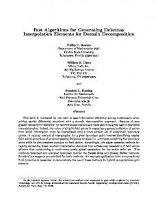
(a) Fig. 2. Flowgraph of a 16-point IMDCT using algorithm IMDCT-II. Multiplications by appropriate sines and cosines are indicated, but not shown explicitly.
and
(b) Fig. 1. Flowgraphs of a 16-point IMDCT using algorithm IMDCT-I. (a) IMDCT-I. (b) IMDCT-I simplified.
the odd samples. Thus, a decomposition into sines and cosines is required. Equation (1) becomes
After this decomposition and some manipulation, each summation is separated into summations over the odd and even samples similar to a decimation-in-time FFT. The whole process is repeated as many times as necessary. The flowgraph of a 16-point IMDCT using this algorithm is shown in Fig. 2. The required numbers of additions and multiplications are and , respectively. It can be clearly observed that IMDCT-I is the most efficient of the three algorithms in terms of the number of arithmetic operations. IMDCT-II is less efficient than IMDCT-I, but it is far more efficient than the direct computation for big . Furthermore, as will be shown in Section III, IMDCT-II has advantages for fixed-point implementation over IMDCT-I. III. FIXED-POINT ERROR ANALYSIS
for
(2)
for
(3)
and
where
Although the IMDCT-I algorithm is efficient, the nature of its twiddle factors (which are secants) renders it unsuitable for a fixed-point implementation. The IMDCT-II algorithm, however, is more suitable for fixed-point computations due to the dynamic range of its twiddle factors, which are sines and cosines, even though it requires more operations and more memory than the IMDCT-I algorithm. Hence, we will investigate the fixed-point errors produced by the IMDCTII algorithm. Specifically, we will look at the number of erroneous bits and the number of significant bits at the output. The computation of the IMDCT was done as follows. The were first normalized so that input values . Then, the inputs to each adder were shifted right by one bit to avoid overflow. From Fig. 2, it is observed that the structures of the first and the last stages differ from those of the
FAN et al.: INVERSE MODIFIED DISCRETE COSINE TRANSFORM
63
intermediate stages. Let be the maximum of the absolute values of the input. The maximum increases to at most after the first stage, to after the second stage is , to after because after the last stage. the third stage, and to , By inductive reasoning, it may be concluded that for , of the absolute values of the output is the maximum, , at most. Numbers are shifted right by one bit every time before an addition to avoid overflow. Although the nominal binary point remains at the same location, the implicit or actual binary point shifts to the right as the numbers move through the stages. There is only one addition at both the first stage and the last stage, so the implicit binary point shifts right by one bit at each. There are two additions at each of the intermediate stages, so the implicit binary point shifts right by two bits here. Finally, there is only one addition at the last stage, so the implicit binary point shifts right by one bit. Thus, bits for an the implicit binary point shifts right by -point IMDCT. If , then This means that the implicit integer part bits. Actually, of the output requires fewer than the maximal number of bits required by the implicit integer The length of part is both the input register and the twiddle factor register is bits. Then, the maximal number of bits remaining after removing the leading zeros from the maximum of the absolute values of the output registers is
TABLE I ERRORS
TABLE II NUMBER OF ERROR BITS
(4) Assume that no overflow occurs before each right shift, then one bit is lost at both the first stage and the last stage, and two bits are lost at each of the intermediate stages. Hence, the minimal number of bits remaining after removing the leading zeros from the maximum of the absolute values of the output registers is (5) and are Equations (4) and (5) showed that both dependent of the register length, , as well as the IMDCT length, . The experiments were performed on 20 sets of and . The final outGaussian random sequences for each puts were compared with those of the floating-point IMDCT. The results are presented in Table I. It is observed that the last bit of the register is uncertain (or inaccurate) regardless of the register length. The number of actual significant bits remaining and decreasing . at the output decreases with increasing To evaluate the performance of the perfect reconstruction using our fixed-point IMDCT-II algorithm combined with the subsequent window and addition, we did the following experiment. The floating-point window and MDCT were applied to a random sequence of 16-b integers. Those outputs were then scaled and quantized to fit into -bit registers on a frame-by-frame basis. The frames were 50% overlapping. The fixed-point IMDCT, windowing, and overlapping-and-adding were applied to the scaled and quantized MDCT outputs. The final samples were compared with the original samples. The experiments were performed on 20 frames of Gaussian random
sequences for each in Table II.
and each
. The results are presented
IV. CONCLUSION The IMDCT is used as part of perfect reconstruction process in some audio decoders. We are not aware of any other published article specifying the register length of a fixed-point digital signal processor required to compute IMDCT’s for some given criteria [7]. If there is no quantization and encoding involved, the reconstructed samples are identical to the original samples. However, it is inevitable that in audio encoding some bits of the samples are lost as a result of quantization and encoding. Therefore, it is desired that one avoids further bit losses during the reconstruction at the decoder. Based on our experimental results, we determined that using the IMDCT-II algorithm, 33-b registers are required for a 1024-point IMDCT in order to perfectly reconstruct 16-b integer samples. ACKNOWLEDGMENT The original version of this article has undergone numerous constructive changes at the suggestion of the reviewers. REFERENCES [1] R. N. Bracewell, “The fast Hartley transform,” Proc. IEEE, vol. 72, pp. 1010–1018, Aug. 1984. [2] K. Brandenburg et al., “ASPEC: Adaptive spectral entropy coding of high quality music signals,” in Proc. 90th AES Conv., Paris, France, Feb. 1991.
64
[3] P. Duhamel, Y. Mahieux, and J. P. Petit, “A fast algorithm for the implementation of filter banks based on time domain aliasing cancellation,” in Proc. IEEE ICASSP, 1991, pp. 2209–2212. [4] B. G. Lee, “A new algorithm to compute the discrete cosine transform,” IEEE Trans. Acoust., Speech, Signal Processing, vol. ASSP-32, pp. 1243–1245, Dec. 1984. [5] H. S. Malvar, “Fast computation of discrete cosine transform through fast Hartley transform,” Electron. Lett., vol. 22, pp. 352–353, Mar. 27,
IEEE SIGNAL PROCESSING LETTERS, VOL. 6, NO. 3, MARCH 1999
1986. [6] J. P. Princen, A. W. Johnson, and A. B. Bradley, “Subband/transform coding using filter bank design based on time domain aliasing cancellation,” in Proc. IEEE ICASSP, 1987, pp. 2161–2164. [7] S. R. Quackenbush, private communication, 1994. ˇ c and M. Popovi´c, “A new efficient implementation of the oddly [8] D. Sevi´ stacked Princen–Bradley filter bank,” IEEE Signal Processing Lett., vol. 1, pp. 166–168, Nov. 1994.