the Butler for permission to start competing for forks (action askButler()), .... The State Diagram of class Butler is presented in Figure 11. The ..... Benjamin Cum-.
On Formalizing UML with High-Level Petri Nets Luciano Baresi and Mauro Pezz`e Dipartimento di Elettronica e Informazione – Politecnico di Milano Piazza Leonardo da Vinci, 32 – 20133 Milano, Italy tel.: +39-2-2399-3400 – {baresi|pezze}@elet.polimi.it
Abstract. Object-oriented methodologies are increasingly used in software development. Despite the proposal of several formally based models, current object-oriented practice is still dominated by informal methodologies, like Booch, OMT, and UML. Unfortunately, the lack of dynamic semantics of such methodologies limits the possibility of early analysis of specifications. This paper indicates the feasibility of ascribing formal semantics to UML by defining translation rules that automatically map UML specifications to high-level Petri nets. This paper illustrates the method through the hurried philosophers problem, that is first specified by using (a subset of) UML, and then mapped onto high-level Petri nets. The paper indicates how UML specifications can be verified by discussing properties of the hurried philosophers problem that can be verified on the derived highlevel Petri net.
1
Introduction
Object-oriented methodologies are increasingly used in software development [19]. Despite the proposal of several formally based object-oriented methods ([10,6]), current industrial practice is still dominated by informal notations, such as OMT ([27]), Booch ([7]), Jacobson ([16]), which have merged into the Unified Modeling Language (UML, [11]). The success of these methodologies is due to user-friendly intuitive graphical representation, good tool support, and traditional skepticism of practitioners against formal methods. Unfortunately, the lack of dynamic semantics of such notations limits the capability of analyzing defined specifications. CASE tools ([18,28,20]), which support this kind of object oriented methodologies, provide powerful analysis capabilities as to syntactic and static semantic properties, but they do not address dynamic semantic analysis, that is, execution, testing, reachability analysis, whose benefits have been widely recognized [31]. Researchers are trying to introduce dynamic analysis capabilities early in the requirements specification by either proposing new formally defined requirements specification notations or adding formality to existing informal notations. New formally defined specification notations ([13]) have been widely experimented, but they succeeded only in specific industrial sectors, such as the design of telecommunication protocols or safety critical applications, where the high costs G. Agha et al. (Eds.): Concurrent OOP and PN, LNCS 2001, pp. 276–304, 2001. c Springer-Verlag Berlin Heidelberg 2001 �
On Formalizing UML with High-Level Petri Nets
277
of failures deeply modify the cost-benefit tradeoff. Attempts to add formal semantics to existing informal notations ([6,32]) barely modify end-user interfaces and interaction modalities, thus overcoming one of the major obstacle for breaking into much larger industrial sectors. The most popular approaches consist in defining translation algorithms that provide given specification notations with fixed semantics. By applying these algorithms users define a formal model that is equivalent to the original informal specification. Unfortunately, the results are particular formalizations of some notations, which, even if well suited for some application domains, cannot easily be generalized. Recently, we investigated a new rule-based approach that allows users to associate different semantics with the same notation. Such an approach, called CR approach ([3], Customization Rules Approach), allows users to fit their interpretations of an informal notation by defining particular set of rules. Users do not only ascribe their semantics to the notation they are familiar with, but they can exploit all the benefits of a formal engine (simulation, analysis) without even knowing that it exists. This approach has been successfully validated by ascribing formal semantics to several data flow-based notations, such as different dialects of structured analysis ([2]) and to new special-purpose notations ([4,23]). Object-oriented notations impose further requirements to the CR approach. Specific features such as inheritance, polymorphism, multiple overlapping views of the same features, and the emphasis on non-strictly operational aspects present new challenges. The goal of this paper is to demonstrate the suitability of the CR approach for the definition of the dynamic semantics of UML. The paper does not present the set of rules that formally define UML. It illustrates rather intuitively the automatic mapping of UML to high-level Petri nets through the hurried philosophers problem. The paper also indicates how we can prove important properties of the problem by analyzing the high-level Petri net derived from the UML specification. This paper is organized as follows. Section 2 briefly sketches the CR approach. Section 3 discusses a possible use of the CR approach for formalizing UML. Section 4 shows the applicability of the approach to the hurried philosophers problems. Finally, Section 5 concludes by indicating the ongoing work.
2
CR Approach
This section describes a flexible framework for defining the syntax of graphical notations, for expressing their operational semantics through a mapping onto an operational formal model, and for presenting the results of dynamic analysis of the formal model in terms of the graphical notation. A notation is defined by means of three sets of rules, that specify the abstract syntax, the semantics, and the visualization of dynamic analysis results, respectively. Abstract syntax rules define the elements of the graphical notation and their connectivity. Semantic rules define the dynamic behavior of the notation as a transformation in a formal operational model. Visualization rules describe the presentation of the results of dynamic analysis on the formal model in terms
278
L. Baresi and M. Pezz`e
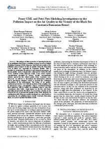
of the chosen graphical notation. Concrete syntax – not considered here – can easily be inherited from existing CASE technology. Figure 1 illustrates the approach. The general framework comprises a graphical (specification) notation and a formal model. Application specialists define their models by using the graphical notation, for example UML. User models are scanned to automatically build the formal representation that corresponds to the graphical specification. The corresponding formal model gives semantics to user models and provides dynamic analysis capabilities. Semantic properties of the graphical specification can be checked on the formal model. Visualization rules translate the analysis results in terms of the graphical notation. In this way, domain experts exploit the benefits of formality without having to care about it. They can execute and analyze their models without being proficient in the formal model. Graphical Specifications Notations (e.g., UML)
Formal Kernel Model (e.g., Petri nets) Abstract Syntax Rules Semantic Rules
Visualization Rules
Fig. 1. The CR approach.
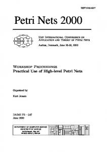
The definition of the abstract syntax and semantics of graphical notations requires the capability of designing rules to specify graphical languages. The framework proposed in this paper refers to the well known theory of graph grammars [22]. Two graph grammars, called Abstract Syntax Graph Grammar (ASGG) and Semantic Graph Grammar (SGG), define the abstract syntax and the semantics of the notation. Each ASGG production corresponds to a SGG production. User modifications on models defined with the graphical notation are captured by means of ASGG productions; the associated SGG productions describe how to automatically update the corresponding formal model. By applying a pair of ASGG and SGG rules, we define also a correspondence between the (abstract) elements of the user model and the elements of the corresponding formal model. Such a correspondence is used by visualization rules. A sample pair of ASGG and SGG rules is illustrated in Figure 2. The two graph grammar rules are given in a graphical style. A rule is a directed graph whose nodes are divided in three parts. The bottom left part indicates the ele-
On Formalizing UML with High-Level Petri Nets
279
ments on which the rule applies; the bottom right part indicates the elements introduced by the application of the rule; the top (embedding) indicates how the new elements have to be connected to the graph. Graph grammar nodes correspond to syntax elements of the specified notation, that is, either nodes or arcs. For example, in the bottom right part of Figure 2(a) nodes 1 and 2 represent nodes of type object, while node 3 represents an arc of type method invocation. Graph grammar arcs indicate relations between the elements of the notation. For example, the graph grammar arcs from node 1 to node 3 and from node 3 to node 2 represent relations connect between the nodes. Arcs belonging to the bottom left part of a rule define the connections (relations) that must exist among selected nodes - to apply the rule. Arcs in the bottom right part of a rule define the relations established by applying the rules. Arcs crossing the border between the bottom left and top parts of a rule select the nodes in the existing graph to which the newly created nodes (bottom right part) will be connected. Arcs crossing the border between the top and the bottom right parts of a rule set the connections between the added subgraph and the nodes identified so far.
7 8 9 10
P
O
1
O
1
V 2
1 3
m O 2
P 3
V
P
V 5
6
4
O 2
3.name = 3.kind = "method invocation"
(a) Syntax Rule
5.type = 1.type 6.type = 2.type
(b) Semantic Rule
O: object m: method invocation P: parameter V: value Fig. 2. AddMethodInvocation: abstract syntax and semantic rules.
The pair of rules of Figure 2 corresponds to adding a method invocation between two objects (UML Collaboration Diagrams, addressed in Section 3.1). The abstract syntax rule (2(a)) can be applied to two nodes of type object (nodes
280
L. Baresi and M. Pezz`e
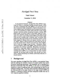
1 and 2 of type O, in the bottom left part of the rule) and results in adding an arc of type method invocation between them (node 3 of type m in the bottom right part). The same numbers associated with the nodes in the bottom left and bottom right parts indicate that the two objects are kept in the graph together with their connections. The semantic rule (2(b)) applies to the two pairs of nodes of type parameter and value that correspond to the two objects selected by the abstract syntax rule (pairs �1, 2� and �3, 4�, of nodes of type P and V ). The four places are “fused” into two new places of type P and V , that represent the actual invocation of the method. The “fusion” is modeled by removing the four places and introducing two new ones. The connections with the embedding force the new P node to be connected to the same arcs to which the two old P nodes were formerly connected, and similarly for the new V node. Figure 3 shows a sample application of the rule of Figure 2.
m2
m2
O1
O1 O2
O2 m3
O3
O3 m1
m1
(a) Abstract Syntax View
O1net P
P V
V
m3o m3i
m1 O2net P
V P
O1net P
V
m2
P V
m1 O2net
V
P
V
m2
m3
O3net
O3net
(b) Semantic View Fig. 3. A sample application of rule AddMethodInvocation of Figure 2.
Often graphical notations are textually annotated. Textual annotations must suitably be translated into the operational formal model. For example, classes of UML Class Diagrams are annotated with attributes and methods. Textual parts of graph grammar rules are used to define the correspondences between textual attributes of the graphical notation and the elements of the formal model. For example, the textual rules of the ASGG production of Figure 2(a) indicate that
On Formalizing UML with High-Level Petri Nets
281
the name of node 3 is supplied by users and its type is method invocation. In the SGG production of Figure 2(b) the type of the new places 5 and 6 is equal to the type of the removed places 1 and 2, respectively. Visualization rules translate states and events of the semantic model in proper representations of the graphical elements. A textual grammar describes the mapping by referring to the types of the objects introduced by syntax and semantic rules. Figure 4 shows the visualization rule that maps the firing of a transition tId of type stateTransition to a set of (abstract) visualization events on UML elements. Readers not familiar with C-like syntax can simply skim through Figure 4: The rule, triggered by the firing of a transition tId of type stateTransition, selects: – All places of type P (parameter) in the preset of tId and associates them with the readParameters visualization event to visualize all the actual parameters of the invoked method. – All places of type S (state) in the preset of tId and associates them with the leaveState visualization event to visualize the current state of the finite state machine and the fact that it is about to change. – All places of type V (value) in the postset of tId and associates them with the writeValues visualization event to visualize all values produced by executing the method. – All places of type S (state) in the postset of tId and associates them with the enterState visualization event to visualize the new current state of the finite state machine. Customization rules can syntactically be checked to verify the existence of a rule for each construct of the modeled notation and to verify the syntactic matching of the rules. Formal semantic checks are not possible, since a set of customization rules capture a particular interpretation, and thus, it should be validated with respect to the “idea” of the notation implicitly assumed while writing the rules. However, customization rules can be verified by inspection, testing, and animation. Inspecting the high-level Petri nets produced on relevant examples can reveal problems in the customization rules; execution and analysis of well understood benchmarks could reveal unexpected behaviors of the highlevel Petri nets that may be caused by erroneous customization rules. As in the case of compilers, customization rules can produce erroneous semantic interpretations that reflect in spurious behaviors. Only user experience can distinguish between errors in the specification and errors in the customization rules. Such errors are the price paid to the flexibility of the CR approach: the more unstable (flexible) the semantics of the informal notation is, the more error-prone the customization rules can be. However, previous experiences in customizing structured analysis allow us to believe the customization rules for an industrial-strength informal specification notation, such as UML, can effectively be validated through inspection, testing, and animation.
282
L. Baresi and M. Pezz`e
– triggering semantic event: firing of a transition tId type stateTransition if (getType(tId) == ‘‘stateTransition") then begin – mark UML elements corresponding to places of type P in the preset of tId with – visualization event readParameters (the event uses the values associated with – such elements) foreach plP (getType(plP) == ‘‘P") in preset begin entityId = getAbsId(plP); eventType = ‘‘readParameters"; eventPars = [("value", compute(plP))]; end – mark UML elements corresponding to places of type S in the preset of tId with – visualization event leaveState (the event causes the system to leave the state – represented with such elements) foreach plS (getType(plS) == ‘‘S") in preset begin entityId = getAbsId(plS); eventType = ‘‘leaveState"; end – mark UML elements corresponding to places of type V in the postset of tId with – visualization event writeValues (the event defines the values associated with – such elements) foreach plP (getType(plP) == ‘‘V") in postset begin entityId = getAbsId(plP); eventType = ‘‘writeValues"; eventPars = [("value", compute(plP))]; end – mark UML elements corresponding to places of type S in the postset of tId with – visualization event enterState (the event causes the system to enter the state – represented with such elements)
end
foreach plS (getType(plS) == ‘‘S") in postset begin entityId = getAbsId(plS); eventType = ‘‘enterState"; end
Fig. 4. An example of Visualization Rule.
On Formalizing UML with High-Level Petri Nets
3
283
Formalizing UML
Formalizing UML with the CR approach presents new challenges and problems. Object-oriented features like inheritance, polymorphism, multiple overlapping views, and emphasis on non-strictly operational aspects must carefully be studied. Possible incompletenesses and inconsistencies of UML specifications – due to the possibility of defining different views of the model – complicate the task of defining formal dynamic semantics. In UML, several non-homogeneous views can capture different details of the same components and often overlap. For example, Class Diagrams can describe only a subset of the classes defining the application; Interaction Diagrams provide a snapshot of a group of objects cooperating to achieve a common goal. Formalization must be able to capture different details from different sources, integrate them, and – if possible – identify and solve inconsistencies. This paper illustrates a possible use of the CR approach to ascribe semantics to consistent UML specifications by means of high-level Petri nets ([14])1 . We do not present all the details of the customization rules (graph-grammar productions) that define the abstract syntax and the semantics of UML, but we illustrate the semantic aspects by describing the underlying high-level Petri nets. Due to space consideration, we show only a sample of the details (predicates and actions) associated with the high-level Petri nets in the Appendix. 3.1
UML
This section briefly introduces UML. Readers proficient in the notation can either skip or skim the section. An UML specification ([11]) comprises 7 kinds of diagrams: Use-Case Diagrams describe user scenarios. They define the possible interactions between the system under development and the external actors. Class Diagrams define the classes and/or packages (groups of classes) that compose the system and the relations among them: – associations (undirected arcs) represent conceptual relationships between classes. The relationships can be clarified by defining the roles played by each class in the relationship. – aggregations (arcs with a white diamond head) represent part-of relationships. Objects of the class at the diamond head “contain” (references to) objects of the class at the tail. Compositions (arcs with a black diamond head) are heavier aggregation relations. Composition restricts aggregation by either requiring an object to be part of one other object only, or by binding the life of the “contained” object to the life of the “container” object. – generalizations (arcs with a white arrow head) represent inheritance relationships. 1
An introduction to high-level Petri net is presented in the Appendix.
284
L. Baresi and M. Pezz`e
Figure 7 shows the class diagram for the case study. The diagram shows associations, generalizations and aggregations. Interaction Diagrams give snapshots of the interactions among objects. They describe how groups of objects cooperate in some behavior. In UML, there are two kinds of Interaction Diagrams: Collaboration Diagrams: Objects are shown as icons, while messages (method invocations) are represented with arrows. The sequence among messages is indicated by numbering the messages. A sample collaboration diagram is shown in Figure 14. Sequence Diagrams: Objects are shown as boxes at the top of vertical dashed lines and messages are drawn with (horizontal) arrows between the dashed lines (objects). Messages are ordered from top to bottom. State Diagrams describe the dynamics of each class as a Statechart [15]. Events and actions correspond to invocation of services (methods, from an implementation-oriented perspective) that are exchanged among objects (i.e., the arcs among entities in the Interaction Diagrams). Messages exchanged among objects are treated according to the defined communication type: simple, synchronous, balking, timeout, and asynchronous. Sample state diagrams can be found in Figures 8, 9, 10, and 11. Activity Diagrams combine SDL [29] and Petri net features to provide a means for specifying the behavior of tasks that present internal parallelism. Package Diagrams describe the partitioning of the system into modules (UML packages). Deployment Diagrams describe how packages and objects are allocated on processors (or on more general hardware components). 3.2
Towards Customization Rules
In this paper, we deal with Class Diagrams, State Diagrams, and Interaction Diagrams. From the semantics viewpoint, Collaboration Diagrams and Sequence Diagrams can be considered different concrete views of the same elements, and thus can be treated similarly. Activity Diagrams, even if they could be useful in deriving the dynamic behavior of designed systems, are not addressed in this work. Package Diagrams and Deployment Diagrams are not considered since they specify the system at the design level, whereas here we concentrate on requirements definition. Class Diagrams. Class Diagrams indicate the classes that compose the system, the (static) relations among them (associations, aggregations, and generalizations), and the external interfaces of the classes, that is, the services provided by the classes. From the semantic viewpoint, classes identify the subnets that will define the whole model and the services provided by the classes. Services are represented with pairs of high-level Petri net places, which indicate service requests and returned values. The type of the first place models the types of the formal parameters associated with the service invocation; the type of the receiving place models the types of returned values. Figure 5 presents an example: the high-level Petri net of class Fork, which is discussed in detail in Section 4.
On Formalizing UML with High-Level Petri Nets
285
Fork id void add() void remove() boolean get() void release() boolean required() boolean released()
Add
Release
Released
Fork
Required
Get
Remove
Fig. 5. The high-level Petri net corresponding to class Fork.
State Diagrams. The behavior of each class is described with a State Diagram, that is, a Statechart [15]. State Diagrams, modeling different classes, interact through exchanging invocations of services (messages). States are annotated with the identifier of the state and the action performed in the state. Transitions are annotated with labels that indicate the event that trigger the transition (above the line) and the actions produced by the triggered transition (below the line). An empty event indicates that the transition can fire spontaneously, while an empty action indicates that the transition produces no action. States are modeled with high-level Petri net places, and transitions with high-level Petri net transitions. Service invocations are modeled by connecting high-level Petri net transitions to the places modeling the service in the class’s interface. Figure 6 illustrates the different translation schemas, corresponding to different kind of interactions. Examples of translations of State Diagrams are given in the case study in Section 4. Interaction Diagrams. Interaction Diagrams identify the matching between the requests and the services. The same information could be obtained by matching the names of required and exported services in Class Diagrams and State Diagrams. Interaction Diagrams are used to make these connections explicit and to solve conflicts of method invocations due to late-binding and polymorphism. The services and their invocations are modeled with separate places, that are “merged” according to the information provided by Interaction Diagrams. The pair of graph grammar rules that define the merging of corresponding places is shown in Figure 2.
286
L. Baresi and M. Pezz`e
State
State Event
Event
Action State
State
(a) Isolated event (not producing an action)
(b) Events producing an action
State State
Invocation Action
Answer
InternalState
State State
(c) “Spontaneous” actions (not triggered by an event)
(d) Method invocation requiring acknowledgment State
State
Invocation Answer
Invocation InternalState Answer
Answer
Invocation InternalState
Answer
InternalState
Invocation
State State
(e) Parallel method invocation requiring acknowledgment
(f) Sequential method invocations requiring acknowledgment
Fig. 6. Translation schemas for State Diagrams
On Formalizing UML with High-Level Petri Nets
4
287
Hurried Philosophers
In this section, we specify the hurried philosophers problem in UML, we illustrate the high-level Petri net derived from the UML specification with the CR approach and its use to prove fundamental properties. The hurried philosophers problem extends the dining philosophers problem [9] by allowing new philosophers to be temporarily invited at the table. As in the original proposal, philosophers must get their left and right forks to eat. If forks are not available, philosophers can ask their neighbors for the forks. Some philosophers have the additional capability of introducing new philosophers, that sit around the table with a new plate and fork, taken from a (bounded) heap of shared resources. The newly arrived philosophers leave the table if asked to leave by the invitee, returning plate and fork to the heap of shared resources. At least two philosophers must be seated around the table. 4.1
UML Model
The Class Diagram of Figure 7 describes the main components of the hurried philosophers model and their relations. Class Philosopher describes the common features of all philosophers. They require interactions with forks and their neighbors to be able to eat. Class ArrivingPhilosopher inherits from InvitingPhilosopher, that inherits from Philosopher. Class InvitingPhilosopher adds service introduceNewPhil to introduce a philosopher and service removePhil to remove a philosopher; class ArrivingPhilosopher adds services for joining and leaving the table. Class Butler prevents deadlocks by restricting the number of philosophers that can concurrently compete for forks; it enforces fairness by granting authorizations to enter the forks competition. Philosophers ask the Butler before starting competing for forks. Class Dispatcher dispatches plates and forks to invited philosophers, and collects plates and forks from leaving philosophers. Since plates and forks are handled similarly, we explicitly model forks only. Class Dispatcher uses class Fork to add new forks. Philosopher. The different types of philosophers (permanently or temporary invited) can naturally be modeled by means of inheritance. Figure 8 shows the State Diagram of class Philosopher and its subclasses InvitingPhilosopher and ArrivingPhilosopher. The properties of the subclasses are highlighted by gray background. Each philosopher starts from state Thinking, where he asks the Butler for permission to start competing for forks (action askButler()), and then move to state Hungry, where he waits for permission. When the Butler allows the philosopher to proceed (event return(ACK)), he tries to pick up his left fork (action leftFork.get()) and enters state AFLF (Asking For Left Fork). If the fork is available (event return(true)), the philosopher enters state HLF (Holding Left Fork). If the fork is not available (event return(false)), he asks the fork to notify its availability (action leftFork.released()), and he waits for the fork to be released in state ANFLF (Asking Neighbor For Left Fork). As
288
L. Baresi and M. Pezz`e
Fork id void add() void remove() boolean get() void release() boolean required() boolean released()
Dispatcher forks fId provide() void collect(fId)
InvitingPhilosopher Philosopher id leftFork rightFork
void introduceNewPhil() void removePhil()
Butler state boolean askButler(pId) pId addGuest() void delGuest(pId) void notifyButler(pId) void reset()
ArrivingPhilosopher void leaveTable(pId) void new(pId, fId)
Fig. 7. Class diagram for the Hurried Philosophers.
soon as the fork is released (event return(true)), he acquires the fork (action leftFork.get()) and moves to state HLF. Notice that the request for service leftFork.get() from state Hungry to state AFLF could result in either a positive or negative answer. The obtained response is the event that determines the next step in the behavior of the philosopher. On the contrary, the invocation of the same service (leftFork.get()) from state ANLF to HLF can result only in a positive answer since the requested fork is in state Available (Figure 9). In fact, the request for leftFork.get() is modeled with a synchronous invocation (see Figure 14) and the fork answers only when it is actually available. Once acquired the left fork, the philosopher checks whether the fork has been required by his left neighbor (action leftFork.required()) and moves to state QLF (Querying Left Fork). If there is a pending request, the philosopher releases the fork and moves back to state Thinking. Otherwise he tries to acquire the right fork with a process analogous to the one followed to get the left fork, and moves to state Eating. When he finishes eating, after a given delay, he releases the forks and goes back to state Thinking. An InvitingPhilosopher can introduce a new philosopher upon finishing eating and before releasing the forks (event introduceNewPhil()). The receipt of this event causes the philosopher to move to state WFD (Waiting For Dispatcher)). In this case, he interacts with the Dispatcher, that provides a new identifier for the fork to be put between the inviting and the arriving philosophers, if any is still available. An InvitingPhilosopher can also remove a
On Formalizing UML with High-Level Petri Nets
289
new(pId, fId) addGuest(this)
Thinking
askButler(this) Hungry
return(true) leftFork.release() return(false) leftFork.released()
return(ACK) leftFork.get() AFLF delay() leftFork.release() rightFork.release()
ANFLF
return(true)
HLF return(true) leftFork.get()
return(NULL) leftFork.release() rightFork.release()
leftFork.required() QLF
removePhil() leftFork.release() rightFork.release() leaveTable(this)
return(false) rightFork.get() return(false) rightFork.released()
ANFRF
return(true) rightFork.get()
leaveTable(pId) leftFork.release() collect(rightFork) delGuest(this)
AFRF
return(true)
Eating
introduceNewPhil() provide() WFD
Fig. 8. State Diagram of class Philosopher.
return(fId) new(this, fId) leftFork.release() rightFork.release()
290
L. Baresi and M. Pezz`e
philosopher before releasing the forks (event removePhil()). Adding or removing philosophers from state Eating simplify the updating of philosophers’ states. An ArrivingPhilosopher is added to state Thinking (event new(pId, fId)). pId and fId identify the right neighbor and the right fork of the philosopher that has to be created (added). An ArrivingPhilosopher can leave the table only from state Eating. Fork. Figure 9 shows the State Diagram of class Fork. Forks can be in either state Available, or state Used, or state Required. A new fork is added (created) on demand by the Dispatcher, that provides the identifier of the new fork. A first get() returns true to confirm the acquisition and it moves the fork to state Used. A second get(), not interleaved with a release(), returns false to notify the current unavailability of the fork and moves the fork to state Required. A release() in either state Used or state Required moves back to state Available. A required returns the current status of the fork. A released() can be served only in state Available. In this way, we define a synchronous communication with the asking object (philosopher), further illustrated by the Collaboration Diagram of Figure 14. Forks are removed (destroyed) by the Dispatcher on demand. add(fId) return(fId) released() return(true)
Available
get() return(true)
release() return(NULL)
required() return(false)
get
Used
get() return(false)
release() return(NULL)
Required
required() return(true)
remove() return(NULL)
Fig. 9. State Diagram of class Fork.
Dispatcher. The State Diagram of Figure 10 describes the behavior of the Dispatcher that grants up to 2 forks. The Dispatcher serves provide() requests by invoking service add() of class Fork and collect() requests by invoking service remove() of class Fork. The Dispatcher of Figure 10 can easily
On Formalizing UML with High-Level Petri Nets
291
be extended to n forks by either adding new states or introducing a state variable to record the number of currently available forks.
2Fork
provide() add(fId)
collect(fId) remove()
1Fork
collect(fId) remove()
provide() add(fId)
Empty
provide() return(NULL)
Fig. 10. State Diagram of class Dispatcher.
Butler. The State Diagram of class Butler is presented in Figure 11. The Butler keeps track of the identity of all the philosophers seated around the table. Events addGuest() and delGuest(pId) are used to keep the list of “active” philosopher up-to-date. Philosophers query the Butler by means of service askButler(). This event generates no action directly, but when predicate readyToEat evaluates to true, the Butler lets the Philosopher start eating. To ensure fairness, this version of the Butler adopts a very simple policy: each Philosopher can eat once, then he has to wait for the other philosophers to eat. Thus predicate readyToEat is satisfied if the philosopher has not already eaten. When a philosopher finishes eating, he notifies the Butler (event notifyButler()). When all the philosophers around the table have eaten once (event readyToReset), the Butler resets (action reset()) his state, and all the philosophers can start eating again. Other policies can be implemented without impacting on the approach described in the paper. 4.2
High-Level Petri Net Semantics
Figures 12 and 13 show the Petri nets produced by applying the CR approach to classes Fork and Dispatcher, respectively. They define the frameworks within which the instances of these classes (tokens) flow.
292
L. Baresi and M. Pezz`e addGuest() return(pId)
delGuest(pId) return(NULL)
Buttler
notifyButler() return(NULL)
readyToReset reset()
askButler(pId)
if (readyToEat) return(true)
Fig. 11. State Diagram of class Butler.
External interfaces are derived from the Class Diagram of Figure 7 – together with State Diagrams – and are modeled with pairs of Petri net places. Each pair represents either an offered or a required service (method) and the corresponding answer. In Figures 12, and 13, interfaces are highlighted with rounded squares. States and transitions of the State Diagrams of Figures 9 and 10 are modeled with Petri net places and transitions, respectively. Each state is modeled with a Petri net place and each transition is modeled with a Petri net transition (see Section 3.1) connected to the places that represent the input and output states and to the places corresponding to the methods triggering the transition. For example, transition get from state Available to state Used of the State Diagram of Figure 9 is modeled with the Petri net transition getT1 from place Available to place Used of the Petri net of Figure 12. Since the transition of the State Diagram is labeled with event get() and action return(true), the corresponding Petri net transition “reads” from the P place of method get(), that represents the service invocation, and “writes” true in the V place of method get(), that represents the answer provided by the service. New objects are instantiated by adding tokens, as done by the subnet corresponding to methods add of class Fork and method new of class ArrivingPhilosopher. Newly created tokens contain the identity of the newly created objects and the class the created object belongs to. The inheritance of properties is governed by the predicates of high-level Petri net transitions. Such predicates forbid tokens corresponding to objects of a superclass to enable transitions modeling services provided by a subclass. In the hurried philosophers problem, classes Philosopher, InvitingPhilosopher and ArrivingPhilosopher share the same subnet, as shown in Figure 15. However, tokens modeling InvitingPhilosophers are prevented to enable transitions that model methods of class ArrivingPhilosopher, for example, method leaveTable. The predicates of the
On Formalizing UML with High-Level Petri Nets
Add
P
P addT
293
Released
releasedT
V
V Available
Release
P
P
releaseT1
V
V releaseT2
Required
Get
getT1
Used
P
P
Remove
removeT requiredT1
V
V
getT2 Required
requiredT2
Fig. 12. Petri net semantics of class Fork.
corresponding high-level Petri net transitions require tokens to indicate class ArrivingPhilosopher as the class they belong to, to fire those transitions. Errors in method invocations (late binding) result in partial deadlocks, that is, tokens stacked in a place. Objects can be deleted by removing the corresponding tokens, as done by methods remove of class Fork, or method leaveTable of class ArrivingPhilosopher. Collaboration Diagrams define the connections among the subnets corresponding to the different classes. The customization rule that adds arcs in Collaboration Diagrams merge the places corresponding to the service in the interfaces of the two objects (classes) exchanging the message. For example, the Collaboration Diagram of Figure 14 models the “starteating” task among a Philosopher P, the Butler B, and a Fork LF (the left fork of P). As indicated by the numbering of the arcs (service invocations), the Philosopher P ask the Butler B for permission (askButler(P)); the Butler B replies with a positive acknowledgment (return(ACK)); the philosopher tries to get his left fork (LF.get()); Fork LF replies false; the philosopher waits on service LF.released() (synchronous communication), and eventually receives a positive answer from the Fork LF. Special arrows indicate synchronous communications. Customization rules merge P and V places of services askButler(), get(), and released().
294
L. Baresi and M. Pezz`e
2Fork
Collect
V
P removeT2
Provide
provideT1
P
V
collectT2
addT1
1Fork
provideT2 removeT1 Remove
P V
V
Add
addT2
collectT1
P
Empty
Fig. 13. Petri net semantics of class Dispatcher.
B : Butler
1: askButler(P) ACK P : Philosopher 2: get()
3: released() 4: get()
true
false
LF : Fork
true
Fig. 14. A Collaboration Diagram for the Hurried Philosophers problem.
On Formalizing UML with High-Level Petri Nets
295
The result of merging the interface places of all the services used in all the Collaboration Diagrams of the example are shown in Figure 15. The figure illustrates the high-level Petri net produced by applying the customization rules, that formalize UML, to the specification of the hurried philosophers problem described in this paper. In Figure 15, subnets corresponding to the different classes are highlighted with boxes; only interface places lie on two boxes that correspond to the joined subnets. The Petri net is reported here to illustrate the semantics, but it is not shown to domain experts, who analyze the Petri net by interacting with the UML model as illustrated in the next section. 4.3
Analysis and Validation
The analysis of a UML specification formally defined by means of a high-level Petri net consists of three main steps: – Define the properties on the Petri net that are equivalent to the properties of the UML specification that users would like to analyze. – Analyze the Petri net with respect to the properties identified so far. – Translate the analysis results on the Petri net in terms of UML. Section 2 briefly illustrates the technique used in the CR approach to define the correspondences between states (markings) and events (firings) of Petri nets and states and events of UML specifications. The textual rules, sketched in Section 2, translate those analysis results that can be expressed with markings and events. This is not a heavy constraint since almost all results can be stated in this way. This section describes how relevant properties of the hurried philosophers problem, defined in UML, can be mirrored on the corresponding high-level Petri net. We do not give the details of the algorithm that maps UML properties to high-level Petri net properties. The correspondence among the different sets of properties for the case study should illustrate the degree of difficulty of such a definition. We also indicate which analysis algorithms for high-level Petri nets can be used to verify such properties. The original proposal of the hurried philosophers problem ([30]) explicitly draws our attention to three main properties: absence of deadlock, boundedness when resources (forks) are bounded, and mutual exclusion of the states of forks (in any case a fork is either in the hand of a philosopher or in the fork heap). Additional properties are required in the partially operational formulation of the problem: fairness (philosophers eat in turn), bounds on the states of the system (there are at least two philosophers at the table), and bounds on the behavior of the system (a philosopher must eat at least once before leaving the table). The UML specification (i.e., an object-oriented model) suggests yet other interesting properties: wrong method invocations, that is, methods invoked in the incorrect state, and presence of critical sequences. In the following, we refer to few main analysis techniques of high-level Petri nets: checks on the structure of the Petri net or on the syntax of transition
T
ttttt
PHILOSOPHER
FORK
DISPATCHER
L. Baresi and M. Pezz`e
BUTLER
296
Fig. 15. The semantic high-level Petri net for the hurried philosophers problem produced with the CR approach illustrated in this paper.
On Formalizing UML with High-Level Petri Nets
297
predicates, net execution, and reachability analysis and model checking. Checks on the structure of the net or on the syntax of the predicates can straightforwardly be automated by means of widely available technology, for example, [8,1]. Execution of high-level Petri nets is currently provided by most CASE tools for high-level Petri nets [8,26]. Reachability analysis and model checking can be performed in many different ways. The reachability graph of the Place/Transition net obtained by ignoring the predicates and actions of the high-level net can be built fairly efficiently by using well-known algorithms. Model checking techniques can be used to prove properties on the reachability graph. Since the reachability graph of the Place/Transition net is only an approximation of the reachability set of the high-level net, only few properties can be proven in this way. Complex properties may require the construction of the reachability graph for the highlevel net, such as the occurrence graph illustrated in [17]2 . We studied many of the properties discussed in this section by using execution and reachability analysis capabilities provided by Cabernet [26]. Absence of deadlocks. Absence of deadlock can be formulated by requiring that there exist no reachable UML states that prevent any method to be invoked eventually. Since method invocations are mapped on transition firings, this property can be formulated in Petri net terms as the absence of markings where no transition will ever be enabled again. Such a property can be tested by executing the Petri net and animating the corresponding UML specification. It can also be verified by building the occurrence graph of the high-level Petri net. Boundedness. Boundedness can be formulated by requiring an upper bound to the number of objects that can be created according to the UML specification. Since objects correspond to tokens, this property can be mapped on the Petri net property that requires the number of tokens to be upper-bounded. Such a property can be tested by executing the Petri net and animating the corresponding UML specification. It can be verified by building the occurrence graph. The reachability graph of the Place/Transition net corresponding to the high-level net can be used instead each time the specification does not make use of predicates to bound resources. For example, boundedness of the number of forks in the system can be proven by means of the reachability graph of the Place/Transition net. This is why the number of tokens of type Fork is bounded by the number of states of class Dispatcher, or, equivalently, the number of Petri net places that model the internals of class Dispatcher. An extension to handle n forks, specified by using a UML state variable, mapped to a variable of the token modeling the Dispatcher, cannot be verified with the reachability graph of the Place/Transition net. Mutual exclusion of the states of forks. Mutual exclusion of the states of Forks can be formulated by requiring each object of class Fork to be in one state of a 2
Occurrence graphs have been originally defined for Coloured Petri nets, that have been shown equivalent to other classes of high-level nets [21].
298
L. Baresi and M. Pezz`e
given set, or, similarly, we can require each token of type Fork to be in one Petri net place of a given set. This can easily be checked statically on either the UML specification or on the corresponding high-level Petri net. The validity of such a property is a consequence of the operational style of both Statecharts, used to model the internals of UML classes, and Petri nets. Fairness. Fairness can be expressed by requiring given sets of UML actions to happen infinitely often. This can easily be expressed by asking the Petri net transitions of the type corresponding to the set of actions to fire infinitely often, i.e., are live ([25]). Traces of Petri net executions can reveal possible problems; model checking on the occurrence graph can be used to prove the property. For example, checking that in none of the path of the occurrence graph the same philosopher eats twice before every other philosopher eats once can be used to prove that philosophers eat in turn. Bounds on the states of the system. Bounds on the system states can be expressed by formulating properties on the states of UML objects (classes). Such properties can be mapped to properties on the markings of the places of the type corresponding to the bounded classes. They can be tested with execution and proven with reachability analysis. For example, asking at least two philosophers to be at the table, that is, asking at least two Philosopher object to be in one of the states characterizing class Philosopher, can be formulated by requiring at least two tokens of type Philosopher to belong to each reachable marking. Bounds on the behavior of the system. Bounds on the behavior of the system can be expressed by stating properties on the sequences of UML events, that is, firing sequences of the corresponding Petri net transitions. Such properties can be tested by executing the net and can be proven on the occurrence graph. The reachability graph of the corresponding Place/Transition net can help in identifying possible wrong sequences, whose feasibility can be checked by executing the high-level Petri net. For example, the property that each philosopher must eat at least once before leaving the table can be formulated by asking that, between the invocation of methods addGuest and leaveTable, the philosopher must be in state Eating. Similarly, place Eating must be marked between the firing of transitions addGuest and leaveTable. Wrong method invocations. Wrong method invocations can be stated by requiring that given methods will never be invoked in the wrong state. For example, the invocation of method get when the fork is in state required would cause a run-time error in the final implementation. Such a property corresponds to requiring that in no markings of the high-level Petri net both places get and required are marked. This is a typical property that can be proven by model checking on the occurrence graph. Animating the net execution cannot prove the validity of such a property, but can increase the confidence in the correct behavior.
On Formalizing UML with High-Level Petri Nets
299
Critical sequences. Critical sequences can be highlighted by requiring specific non-interruptible sequences of method invocations. For example, invocations of methods released() and get() on the same Fork cannot be interleaved with the invocation of other methods to obtain a correct behavior of the system. This translates on requirements on firing sequences that can be tested with execution and proven with model checking on the occurrence graph.
5
Conclusions
This paper presents an exercise on ascribing formal semantics to UML specifications. The method is illustrated by indicating a semantics for the hurried philosophers problem: the UML specification of the problem is mapped onto high-level Petri nets. The paper suggests a generalization of the mapping (a set of rules) that can be used to automatically produce formal semantics of UML specifications by means of high-level Petri nets. The paper indicates how users can analyze UML specifications by querying the corresponding high-level Petri net.
References 1. ARTIS s.r.l., Torino, Italy. Artifex 3.1 – Tutorial, 1994. 2. L. Baresi. Formal Customization of Graphical Notations. PhD thesis, Dipartimento di Elettronica e Informazione – Politecnico di Milano, 1997. in Italian. 3. L. Baresi, A. Orso, and M. Pezz`e. Introducing Formal Methods in Industrial Practice. In Proceedings of the 20th International Conference on Software Engineering, pages 56–66. ACM Press, 1997. 4. L. Baresi, M. Di Paola, A. Gargiulo, and M. Pezz`e. LEMMA: A Language for an Easy Medical Models Analysis. In Proceedings of IEEE Computer Based Medical Systems 97, 1997. To appear. 5. L. Baresi and M. Pezz`e. Towards Formalizing Structured Analysis. ACM Transactions on Software Engineering and Methodology, 7(1), jan 1998. 6. B.W. Bates, J.M. Bruel, R.B. France, and M.M. Larrondo-Petrie. Guidelines for Formalizing Fusion Object-Oriented Analysis Methods. In Conference on Advanced Information Systems Engineering (CAiSE) 96, pages 222–233, 1996. 7. G. Booch. Object-Oriented Analysis and Design with Applications. Benjamin Cummings, second edition edition, 1994. 8. S. Christensen, J. B. Joergensen, and L. M. Kristensen. Design/CPN — A Computer Tool for Coloured Petri Nets. Lecture Notes in Computer Science, 1217, 1997. 9. E.W. Dijkstra. Co-operating Sequential Processes. Academic Press, 1965. 10. E. H. D¨ urr and N. Plat. VDM++ Language Reference Manual. Technical report, IFAD - The Institute of Applied Computer Science, 1995. 11. M. Fowler and K. Scott. UML Distilled: Applying the Standard Object Modeling Language. Addison-Wesley, Reading, Mass., 1997. 12. H. Genrich. Predicate/transition nets. In W. Reisig and G. Rozemberg, editors, Advances in Petri Nets, LNCS 254-255. Springer-Verlag, Berlin-New York, 1987.
300
L. Baresi and M. Pezz`e
13. S. Gerhart, D. Craigen, and T. Ralston. Experience with Formal Methods in Critical Systems. IEEE Software, 11(1):21–28, January 1994. 14. C. Ghezzi, D. Mandrioli, S. Morasca, and M. Pezz`e. A Unified High-Level Petri Net Model For Time-Critical Systems. IEEE Transactions on Software Engineering, 17(2):160–172, February 1991. 15. D. Harel, H. Lachover, A. Naamad, A. Pnueli, M. Politi, R. Sherman, A. ShtullTrauring, and M. Trakhtenbrot. STATEMATE: A Working Environment for the Development of Complex Reactive Systems. IEEE Transactions on Software Engineering, 16(4):403–414, April 1990. 16. I. Jacobson. Object-Oriented Software Engineering–A Use Case Driven Approach. ACM Press/Addison Wesley, 1992. 17. K. Jensen. Coloured Petri Nets. In W. Reisig and G. Rozemberg, editors, Advances in Petri Nets, LNCS 254-255. Springer-Verlag, Berlin-New York, 1987. 18. Mark V Systems. ObjectMaker User’s Guide, 1994. version 3. 19. B. Meyer. Object-oriented Software Construction. Prentice Hall, New York, N.Y., second edition, 1997. 20. MicroGold Software. WithClass97 User’s Guide, 1997. 21. S. Morasca, M. Pezz`e, and M. Trubian. Timed High Level Nets. The Journal of Real-Time Systems, pages 165–189, 1991. 22. M. Nagl. A Tutorial and Bibliographical Survey on Graph Grammars. In V. Claus, H. Ehrig, and G. Rozenberg, editors, Graph Grammars and their Application to Computer Science and Biology, volume 73 of Lecture Notes in Computer Science, pages 70–126. Springer-Verlag, 1979. 23. A. Orso. An Environment for Designing Real-Time Control Systems. Technical Report 97-56, Dipartimento di Elettronica e Informazione - Politecnico di Milano, 1997. 24. C. Petersohn, W.P. de Roever, C. Huizing, and J. Peleska. Formal Semantics for Ward & Mellor’s Transformation Schemas. In D. Till, editor, Proceedings of the Sixth Refinement Workshop of the BCS FACS. Springer-Verlag, 1994. 25. J. Peterson. Petri Net Theory and the Modeling of Systems. Prentice-Hall, Englewood Cliffs, NJ, 1981. 26. M. Pezz`e. Cabernet: A Customizable Environment for the Specification and Analysis of Real-Time Systems. Technical report, Dipartimento di Elettronica e Informazione, Politecnico di Milano, Italy, May 1994. 27. J. Rambaugh, M. Blaha, W. Premerlani, F. Eddy, and W. Lorensen. ObjectOriented Modeling and Design. Prentice Hall, New York, NY, 1991. 28. Rational. Rational Rose: User Manual. 29. O. Færgemand and A. Olsen. Introduction to SDL-92. Computer Networks and ISDN Systems, 26:1143–1167, 1994. 30. C. Sibertin-Blanc. Cooperative Nets. In R. Valette, editor, Application and Theory of Petri Nets 1994, Proceedings of the 15th International Conference, volume 815 of Lecture Notes in Computer Science, pages 206–218, 1994. 31. I. Sommerville. Software Engineering. Addison-Wesley, fifth edition, 1996. 32. E.Y. Wang, H.A. Richter, and B.H.C. Cheng. Formalizing and Integrating the Dynamic Model within OMT. In Proceedings of the 19th International Conference on Software Engineering, pages 45–55. ACM Press, May 1997.
On Formalizing UML with High-Level Petri Nets
A
301
High-Level Petri Nets
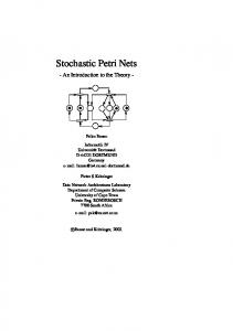
High-level Petri nets are Petri nets augmented with conditions and action on values associated to tokens. High-level Petri nets have been instantiated in several equivalent ways. The most well known classes of high-level Petri nets are Coloured Petri nets ([17]) and Predicate/Transition nets ([12]). In this paper we use HLTPNs, introduced in [14], since it is the model supported by Cabernet ([26]), which is the tool used in our experimental work with the CR Approach. [14] focuses mainly on the introduction of time in high-level Petri nets. In this paper, we refer to the untimed model; timing aspects will be considered in future extensions of our work. We refer to the Petri net extension use in this paper simply as high-level Petri nets. High-level Petri nets are Petri nets, i.e., bipartite connected graphs, where places are associated with types; tokens are associated with variables and values, according to the type of the “container” place; transitions are associated with predicates and actions, according to the types of the places of their pre and postsets. Variables that occur in predicates and actions of transitions are dynamically bounded to variables of tokens in the pre and post-sets of the transitions. A transition t is enabled by a tuple tup − in of tokens in its preset if the predicate of t evaluates to true on the values of the tokens in tup − in. The firing of an enabled transition removes the enabling tuple from its preset and produces a new tuple tup − out of tokens in its postset. The values of tokens in tup − out are obtained by evaluating the action of t on the values of the variables of the enabling tuple. Figure 16 shows a sample high-level Petri net, that corresponds to a subset of class Butler and the invocation of method delGuest by an arrivingPhilosopher. Class Butler is modeled with a place butler always marked, a transition reset, a pair of transitions for each method, and a set of interface places. Transition tt Reset “clears” the token in place Reset when all active philosophers have eaten once after the last reset. Figure 16 shows only the pair of transitions and the interface places corresponding to method delGuest. Transitions LeaveTable and LeftTable model the invocation of and the answer from method delGuest, according to the schema illustrated in Figure 6. Places leaveTableP, eating, leaving, and leaveTableV are part of the model of class philosopher. Figure 16 lists the types associated with the places as C++-like classes, the association of types to places as C++-like objects, predicates and action of transitions as C++-like predicates and functions, tokens as values for the attributes characterizing the type of the place the tokens belong to. Place butler, of type butlerState contains a pair of boolean variables for each philosopher, indicating the state (active or not) and the condition (hungry or not). The token that initially marks place butler indicates two active, hungry philosophers, and two non-active philosophers. Transition reset fires when none of the active philosophers is hungry (i.e., all active philosophers have eaten once after the last reset), as stated by the associated predicate. The predicate compares field active with the negation of field hungry. This is true when all
302
L. Baresi and M. Pezz`e
active philosophers (field active == true) ate after the last reset (field hungry = false) and all non-active philosopher (field active == false) are hungry (field hungry = true, the default value for non-active philosophers). The firing of transition reset sets all philosophers to hungry, as stated by the associated action. eating leaveTableP
0
2
hungry
LeaveTable leaving
1
active
delGuestP
DelGuest butler
Reset
TableLeft delGuestV
true false
leaveTableV
Fig. 16. A sample high-level Petri net. Classes class philosopher { string type; integer id; integer leftFork; integer rightFork; }; class philInfo { boolean active; boolean hungry; }; Places philosopher philId butlerState philPhil
class philPhil { philosopher state; philosopher param; }; class butlerState { philInfo st[3]; } class philId { integer id; };
leaveTableP, eating; delGuestP, delGuestV, leaveTableV; butler; leaving;
Transitions DelGuest predicate butler.st[delGuestP.id].active == true
3
On Formalizing UML with High-Level Petri Nets
303
action delGuestV = delGuestP; butler.st[delGuestP.id].active = false; butler.st[delGuestP.id].hungry = true; LeaveTable predicate (eating.rightFork == leaveTableP.leftFork) && (eating.type == ‘‘arrivingPhilosopher") action delGuestP.id = eating.id; leaving.state = eating; leaving.param = leaveTableP; Reset predicate (butler.st[0].active (butler.st[1].active (butler.st[2].active (butler.st[3].active action butler.st[0].hungry butler.st[1].hungry butler.st[2].hungry butler.st[3].hungry
== == == ==
= = = =
!(butler.st[0].hungry)) && !(butler.st[1].hungry)) && !(butler.st[2].hungry)) && !(butler.st[3].hungry))
true; true; true; true;
TableLeft predicate leaving.state.id == delGuestV.id action leaveTableV = leaving.state.id;
Transition LeaveTable models the request for removing a philosopher from the table. It is enabled by two neighbor philosophers: a philosopher in place leaveTableP asks his neighbor in place eating to leave. This is stated by the first term of the predicate that identifies neighbor philosophers by means of the shared fork. The philosopher that will leave must be of class ArrivingPhilosopher as asked by the second term of the predicate. This is the standard way of forbidding objects of a given class in a inheritance hierarchy to invoke methods of subclasses in the same inheritance hierarchy. Transition LeaveTable produces a token in place delGuestP with the id of the leaving philosopher, and a token in place leaving with both the philosophers involved in the execution of the method (fields state and param).
304
L. Baresi and M. Pezz`e
Transition DelGuest models the method execution. It removes the philosopher from the table only if active, as stated by the predicate. It “moves” the token from place delGuestP to place delGuestV and suitably sets the state of the token modeling the butler. Transition LeftTable is enabled by two corresponding tokens in places leaving and delGuestV, as stated by the predicate. This predicate avoids wrong associations when several philosophers are concurrently executing the same method. Transition LeftTable produces a token in place leaveTableV that indicates the completion of the method execution.