IEEE JOURNAL ON SELECTED AREAS IN COMMUNICATIONS, VOL. 19, NO. 5, MAY 2001
883
On Iterative Decoding in Some Existing Systems Jan Bajcsy, Member, IEEE, Chan-Vee Chong, Student Member, IEEE, D. A. Garr, J. Hunziker, and Hisashi Kobayashi, Fellow, IEEE
Abstract—Iterative decoding is used to achieve backward compatible performance improvement in several existing systems. Concatenated coding and iterative decoding are first set up using composite mappings, so that various applications in digital communication and recording can be described in a concise and uniform manner. An ambiguity zone detection (AZD) based iterative decoder, operating on generalized erasures, is described as an alternative for concatenated systems where turbo decoding cannot be performed. Described iterative decoding techniques are then applied to selected wireless communication and digital recording systems. Simulation results and utilization of decoding gains are briefly discussed. Index Terms—Concatenated coding, digital recording systems, iterative decoding, wireless communication systems.
I. INTRODUCTION
A
PRIMARY objective of any digital communication system is to transmit information at the maximum possible rate and receive it with minimum distortion or errors. The concept of capacity from channel coding theorem upper-bounds the transmission speed at which reliable communication is possible on a large class of channels. Because only long codewords can guarantee small decoding errors at high transmission rates and the codebook size increases exponentially with the codeword length, finding the message best matching received channel data becomes a difficult task. As a result, finding good codes with practical decoders turned out to be the main challenge in achieving reliable transmission at rates close to the channel capacity. The most powerful channel coding techniques known today are based on concatenation, that is combination of smaller encoders at the transmitter. The data are encoded by a cascade of encoders and this in effect creates a powerful code of large block length. The concept appeared originally in Elias’ product codes [1], was conceptually utilized in Gallager’s low density parity check (LDPC) codes [2], and got named and developed to schemes with many practical applications in Forney’s conManuscript received May 2000; revised December 20, 2000. This work was supported in part by the National Science Foundation, the New Jersey Commission on Science and Technology, Asahi Chemical Co. Ltd, Seiko Communications Systems, and the Ogasawara Foundation for the Promotion of Science and Engineering. This paper was presented in part at GLOBECOM’98, Sydney, Australia, November 1998, and at ICC’99, Vancouver, Canada, June 1999. J. Bajcsy is with the Department of Electrical and Computer Engineering, McGill University, Montreal, QC, Canada H3A-2A7 (e-mail: jbajcsy@tsp. ece.mcgill.ca). C.-V. Chong is with the Department of Electrical Engineering and Computer Science, M.I.T., Cambridge, MA 02139 USA (e-mail:
[email protected]). D. A. Garr, J. Hunziker, and H. Kobayashi are with the Department of Electrical Engineering, Princeton University, Princeton, NJ 08544 USA (e-mail:
[email protected]). Publisher Item Identifier S 0733-8716(01)03906-3.
catenated codes [3]. Optimal decoding of concatenated codes on most channels would be, in most cases, too complex to be practical so suboptimal decoders have been proposed in the literature and got applied in practical systems. The basic idea is to utilize decoders of constituent encoders and decode noisy channel data either in one sequence of steps or repetitively. The latter approach, in particular turbo decoding principle proposed originally for parallel concatenated convolutional codes by Berrou et al. [4], achieved unprecedented performance only a few tenths of a dB from capacity of the additive white Gaussian channel. Further studies showed successful use of turbo decoding principle in many concatenated systems of practical interest [5]–[8]. The structure of this paper is as follows. Concatenated encoding techniques are first described, viewing encoders and decoders as mappings. Using this setting, iterative decoders for systems with concatenated structure are reviewed, including an ambiguity zone detection (AZD) based iterative decoder. The iterative decoders are then applied to a recording system, a GSM system, and a wireless system with diversity. Simulation results and discussion of performance improvement utilization are presented. II. CODES FROM CONCATENATION AND THEIR DECODING A. Preliminaries In a digital communication system encoder is a mapping from to a codebook a set of messages (1) where is a subset of sequences which are allowed as inputs to the channel or the next stage encoder. Similarly, decoder is a mapping from the set of received channel data into a decision set (2) Encoders in this setting are devices that introduce a redundancy and/or memory constraint, as the data pass through them in digital communication, e.g., error-correcting codes, run-length limited codes, or constrained channels but may also interleave (permute) the symbols prior or after application of the constraint. Given encoder or decoder can be implemented using different algorithms, e.g., a minimum distance decoder for a binary linear block code on a binary symmetric channel can be implemented via exhaustive search, syndrome decoding algorithm, or Viterbi algorithm that uses code’s trellis structure. Unless stated otherwise, we will assume binary encoders, and . Log-APP ratios (logi.e., arithmic ratios of a posteriori probabilities) are defined for bi-
0733–8716/01$10.00 © 2001 IEEE
884
IEEE JOURNAL ON SELECTED AREAS IN COMMUNICATIONS, VOL. 19, NO. 5, MAY 2001
Fig. 1. Schematic block diagrams of two encoders concatenated in (a) parallel (b) series. (Note that for notational convenience, interleavers are considered to be parts of encoding maps.)
nary random variables and vectors, e.g., for binary vector channel data
and
Fig. 2. Schematic block diagrams of iterative decoders for two codes concatenated in (a) parallel (b) series.
(3)
where outer and inner encoders are described as
Decisions about message bits can be then formed via thresholding, denoted by the use of unit-step function
(7)
if otherwise or its vector version
.
B. Encoder Concatenation Concatenation of encoders in a communications system may occur because of the original transmitter or receiver architecture, or due to the channel over which the data are transmitted in a practical communication system. For instance, a serial concatenation may result from cascading several encoders at the transmitter, e.g., a product code, followed by a run-length limited code and a partial response channel, as often found in a digital recording system. It may also be due to a channel subject to multipath fading or ISI in a coded system, as is the case in the GSM system [9]. Parallel concatenation can be a result of diversity, when multiple transmissions and/or receptions occur in the time, space, or frequency domain. It can be also be a result of an automatic repeat request (ARQ) protocol when another set of channel data about the same source message becomes available at the receiver. A hybrid concatenation occurs if a combination of the aforementioned factors is present in a system, as in the message watch paging system of Seiko Communications. The parallel concatenation of two encoders, shown in Fig. 1(a), can be formally written as (4) where
The encoder concatenation concept and definitions can be easily extended to cases where we deal with more encoders. For instance, the original turbo encoder from [4] can be rewritten in this setting with (4) and (5) as follows. and encoder is based on the nonuniform interleaver and applying the rate 1/1 recursive convolutional ). Encoder is based code (no systematic part, on systematic encoding with the recursive convolutional code ). ( C. Iterative Decoding of Concatenated Codes 1) Turbo Decoding: For data encoded by concatenated encoders and corrupted by channel noise, finding an optimal decoder is usually difficult for commonly used criteria, e.g., minimization of sequence error probability (MLSE) or bit error probability (MAP criteria). Except for a few simple cases, such a decoder constructed by conventional means would be too complex to be practical. Turbo decoding is the best suboptimal scheme known today. An iterative turbo decoder is schematically shown in Fig. 2(a) in case of two encoders concatenated in parallel. It connects the two subdecoders in a loop, where soft decision decoding information is gradually refined as it is passed between the decoders and can be expressed as
(8) . The with the initial condition chosen to be and are defined using log-APP decoding vector functions ratios
(5)
(9)
Similarly, serial concatenation of two encoders, depicted in Fig. 1(b), can be formally written as a composite mapping
(10)
(6)
where vectors and , termed extrinsic information, are treated as if they contained independent probabilities (log-ratios) about
BAJCSY et al.: ON ITERATIVE DECODING IN SOME EXISTING SYSTEMS
885
bits in message . [To achieve this formally, and can be defined as realizations of a fictitious Gaussian random vector with .] unit covariance matrix and mean Decisions about the source message bits after the th iteration can be made by forming hard decisions at Decoder 1, e.g., via thresholding (11) is the unit step function defined in Section II-A. where Turbo decoding from (8), when applied to decoding of serially concatenated encoders from (6), (7), is schematically shown in Fig. 2(b). It can be formally described as
The proposed AZD based decoding process is similar to crossword puzzle solving and its spirit is illustrated in the following simple example, while the remainder of the section gives its formal description and addresses implementation issues. Example 2.1: A binary crossword puzzle, shown on the left of (16) is supposed to be solved, i.e., all unknown binary letters denoted by s are to be resolved. Hints state that the sum of symbols is even in each of the first two rows as well as columns. We attempt to resolve the unknown symbols by iteratively applying the row and column constraints. Iteration 1 proceeds as follows
(12) where the initial condition is again chosen to be . The decoding functions and in this setting are defined as (13) (14) where vectors and are treated as if they contained indepen. dent probabilities (log-ratios) about coded bits in The decision about the message bits can be again determined by making hard decisions at Decoder 1, e.g. (15) For a memoryless channel [e.g., additive white Gaussian and can be noise (AWGN)], the decoding functions implemented using the BCJR algorithm. As the iterative process tends to converge reasonably fast, the scheme has practical storage, computational and implementation complexities for encoders with trellis structure of reasonable size. The complexity of the turbo decoder can be lowered by using approximate soft output Viterbi algorithm (SOVA) algorithm [10] in implementing the decoding functions, though the performance slightly worsens. 2) Iterative AZD Based Decoder: This section gives a general description of the AZD based iterative decoder whose initial version has been proposed by Kobayashi and Bajcsy [11]. This decoder builds on the idea of the ambiguity based detection of Kobayashi and Tang [12] in order to obtain a low complexity iterative decoder based on generalized erasures. The technique can be seen as an alternative to turbo decoding, especially in systems where original system design, stringent limitations on the overall receiver complexity or limited availability of practical soft decision decoders for some codes (e.g., Reed Solomon codes) may prevent turbo decoding. The AZD based iterative decoder can be seen as an application of the bisection method principle to suitably formulated decoding problem for concatenated encoders, while the turbo decoder can be seen as an application of the functional iteration technique to decoding in concatenated systems [13]. It is important to note that for channel with pure erasures, independent studies have been done on concatenated code design and iterative decoding by Luby et al. [14], [15].
(16)
No erased digits in the initial array can be resolved using the column-wise hints without possibly making an error, i.e., two erasures in column 1 could be resolved either as or as . The same applies to in column 2. In the second step of iteration 1, row-wise constraints are used is resolved based on the first row constraint. and and still cannot be resolved because they could either both be 1 is not involved in any row constraint. or 0, and Iteration 2 starts with the rightmost expression of (16) and tries to resolve the remaining erasures using again the constraints on columns and rows, i.e.
(17)
, whereas First, single erasure in column 2 is resolved as two erasures in column 1 cannot be uniquely resolved. Applying and the next iteration row-wise constraints then reveals can be started. Iteration 3 starts by using the column constraints and after is found to be 0 (18)
the iterative process stops as all erasures in the original array have been resolved. The described iterative principle can be applied to decoding of two encoders concatenated in parallel (4), (5). Schematic block diagram of AZD based iterative decoder is shown in Fig. 2(a), and it can be formally written as
(19)
886
IEEE JOURNAL ON SELECTED AREAS IN COMMUNICATIONS, VOL. 19, NO. 5, MAY 2001
starting with the initial condition . Assuming for simplicity binary encoders and AWGN channel, have the th coordinate of vector decoding functions their output defined as or
if
(or 1) for all
(20)
otherwise or
if
(or 1) for all
(21)
otherwise utilizing the set of possible candidate messages at each decoder and
III. APPLICATION OF ITERATIVE DECODERS
for all s.t. and for all s.t.
(22)
are chosen based the actual code Thresholds parameters and channel parameters and may be gradually tightened as the and in (21) and (20)]. decoding proceeds [denoted by The decoding decision about the transmitted message is contained in after each iteration. The AZD based iterative decoder proceeds similarly in case of two serially concatenated encoders from (6) and (7). It is schematically shown in Fig. 2(b) and can be written as
(23) . Assuming again bistarting with nary encoders and AWGN channel, vector decoding functions have the th coordinate of their output defined as or
if
(or 1) for all
(24)
otherwise or
if
(or 1) for all
(25)
otherwise where the candidate sets at each decoder are defined as and for all s.t. for all s.t.
(26)
is a systematic encoder, the decoding decision about If the transmitted source message is contained in each iteration. Otherwise, it can be formed at Decoder 1 coordinate wise, i.e., or
if
(or 1), for all
for block codes, while suitably modified SOVA can be used for codes with trellis structure (e.g., for general PR channels, convolutional codes, etc.). In particular, binary erasures at the input of a SOVA decoder do not contribute to calculated path metric, while output erasures are generated for symbols whose reliability is below chosen threshold. The latter rule is based on the distance-based requirement for generating erasures in (24)–(26) and on an observation from [10] that is the distance between the maximum-likelihood decision and the closest codeword (or message, depending on what we decode) differing from in position . The described AZD based iterative decoder easily extends to nonbinary codes and can be applied to decoding in various communication systems.
(27)
otherwise. practically, decoding To implement decoding functions algorithms capable of handling errors and erasures can be used
Iterative decoding techniques from Section II are applied to several existing communications systems with concatenated structure. Since related standards specify the system transmitter side but leave the receiver implementation up to the manufacturers, the proposed solutions are backward compatible in practice. Each studied system is first briefly described, parameters of its transmitter are specified and simulation results of conventional (one-path) receiver and applied iterative decoder are compared. A. Existing Recording Systems The main technical goals in digital recording product development are increased recording density, greater reading speed, higher reliability, and lower cost. Magnetic disk drives and tapes, digital audio tape, and digital video tape are important examples of magnetic recording applications, while compact disc, DVD, and rewritable DVD are among such optical recording systems. In the recording process of many of these systems, the data are first encoded by one or more error correcting encoders, followed by a modulation code and a partial response channel [16]–[18]. The error correcting codes are usually Reed–Solomon (RS) codes or their variants, e.g., shortened codes or product codes. The modulation code is usually a variation of a runlength-limited sequence code which guarantees clock recovery and alleviates the intersymbol interference (ISI) introduced by the channel [19], [20]. The channel with ISI is usually followed by an equalizing filter that confines the span of ISI within a reasonable number of symbols, thus creating, in effect, a partial response (PR) channel. For instance, in digital magnetic recording products or describes the read the PR channel out process. Conventionally used receivers for these systems use a one-path decoding structure, where the PR channel is usually followed by a maximum-likelihood decoder (combined scheme known as PRML proposed originally in [21]) followed by error correcting decoders. We consider a recording system with serial concatenated structure from Fig. 1(b) which has parameters similar to those of the CD, DVD, and digital video tape. The first encoder is and the based on a (28, 24, 5) shortened RS code over block interleaver. The output bytes are interleaved by a second encoder applies a (32, 28, 5) shortened RS code over the
BAJCSY et al.: ON ITERATIVE DECODING IN SOME EXISTING SYSTEMS
887
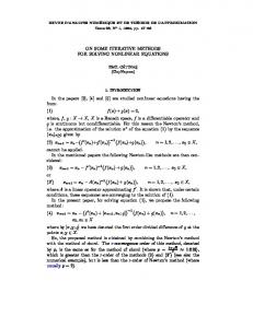
Fig. 3. Recording system performance curves for the conventional and iterative receiver on pure erasure channel.
Fig. 4. Recording systems performance curves for channel with AWGN (rightto-left): Original one-path receiver and iterations 2–4.
same field and interleaves coded bytes by another block-based interleaver. Resulting data are passed onto effective channel which in our systems actually consists of a modulation encoder, PR channel with ML detection and an AZD detector. The modulation encoder maps bits corresponding to each byte into nine bits and these are passed onto a partial response channel. The PR channel includes the ISI channel and the equalizing filter so that has passed through the PR channel is that a sequence mapped into a sequence, which in polynomial form is given by
the output data of the effective channel include correct and wrong bytes as well as erasures. The simulation results are shown in Fig. 4, which depicts the SNR versus residual error rate (BER). The four curves depict the performance after iterations one through four. The first iteration result is equivalent to the result of the conventionally used one-path receiver. For the channel SNR of 7.5 dB, the iterative receiver lowers the BER rate by a factor of almost 1000 after four iterations. Another way to view these results is that decoding gain of about one dB is achieved due to . As the speed of read-out the iterative decoding at BER of is a crucial bottleneck in data recording applications (e.g., rewritable DVDs, magnetic drives, digital magnetic tapes, etc.), achieved decoding gain can be traded for faster reading of the data, i.e., read head spending less time over given data symbols. For instance, one dB decoding gain corresponding to about 20% less needed signal power (assuming constant noise level) can be used to achieve faster data read out by up to 20%, and this can be achieved in a fully backward compatible manner with respect to existing standards. Finally, it is important to remark that the use of turbo codes and turbo decoding/equalization are the focus of active research on the next generation magnetic and optical recording systems. Papers presented by, for instance, Ryan et al. [23], Souvignier et al. [24], and Song et al. [25] contain results of ongoing effort in this area. Furthermore, there have been experimental studies on iterative turbo decoding of product codes based on binary block codes, e.g., for high rate Hamming codes using a neurocomputer [26] or using Chase algorithm [27] to achieve soft-decision decoding of BCH codes [28].
(28) Channel noise corrupts the PR symbols and these are detected via maximum likelihood sequence estimation (MLSE) using the Viterbi algorithm over the PR trellis diagram. The decoded bits are then passed to the modulation decoder which uses redundancy introduced by modulation encoder to decide, whether the data have been received reliably or should be declared as “erasures” or ambiguous digits. We have applied AZD based iterative decoder (23) from Secare based on RS detion II-C2. Decoding functions coding with erasures for appropriate RS codes. First, we tested the decoder on a somewhat simplified model of the recording channel with i.i.d. distributed byte-erasures due to the channel noise. In this case, RS decoders will not introduce any errors in the decoding process but they will be unable to decode if there are excessive erasures. The simulation results, shown in Fig. 3, depict the original erasure rate versus residual byte era, the iterative resure rate. At residual byte erasure rate of ceiver can resolve about two and a half times as many erasures as the one-path receiver. Another way to interpret these results is that at the symbol erasure rate of 15% our decoder outperforms the existing decoder by almost five orders of magnitude. Note that the decoding converges after two to four iterations in most cases, thus making this iterative technique practical from the decoding delay point of view. We then looked at the system performance assuming Gaussian noise corrupts duobinary PR symbols. Note that when the channel noise level is large, the AZD may introduce errors and
B. GSM System In the pan-European digital cellular standard Groupe Speciale Mobile (the Global System for Mobile Communication, or GSM), original error-correcting protection is based on a convolutional outer encoder, while Gaussian-filtered minimum shift keying (GMSK) is used as a bandwidth efficient modulation scheme [9]. GMSK is similar to traditional minimum shift keying (MSK) except that the baseband signal is passed through a Gaussian lowpass filter prior to frequency modulation
888
IEEE JOURNAL ON SELECTED AREAS IN COMMUNICATIONS, VOL. 19, NO. 5, MAY 2001
so the signal spectrum is shaped to make the modulation signal spectrally efficient. In the time domain, this spreads the signal over multiple bit periods and introduces a controlled amount of ISI. Further ISI may be introduced to the received signal by multipaths in the radio channel and the overall transmitter has a serially concatenated structure given in Fig. 1(b), where the GMSK modulator together with the multipath channel act as the inner encoder. In this section, we apply iterative turbo decoder from equation (12), approach also referred to as turbo equalization [6], to improve the conventionally used one-path GSM receiver. Encoder 1 is based on a rate 1/2 convolutional code with generator polynomials (29) (30) which protects only the more important “Class I” bits, whereas the less important “Class II” bits are left unencoded [9]. Resulting data stream is interleaved using the interleaver described in [9] and a 26-bit training sequence
Fig. 5. Simulation results of the GSM system for multipath channel with two significant reflections.
(31) is inserted into the middle of each packet. The combined effects of the Gaussian filtering and the multipath channel can be modof finite duration which eled as a single impulse response is given by (32) at where denotes convolution. By sampling (where is the symbol interval), we obtain the discrete-time . In particular, a binary sequence impulse response , , that enters the GMSK modulator and multipath channel, is transformed into a noiseless complex valued channel sequence (33) represents the initial phase offset of the modwhere ulator. Hence, Encoder 2 has a finite state machine structure and can be represented by a trellis diagram. [At the receiver, the can be eliminated by multiplying the time varying factor of and the effective channel parameters received symbols by are usually estimated using a matched filter based on the training sequence (31).] Iterative decoder (12) has been applied to the described implemented using system with decoding functions SOVA algorithm. We have assumed AWGN corrupting channel from equation (33) and the effect of GMSK/mulsymbols tipath was modeled as a finite shift register encoder with five registers. Some of the simulation results are shown in Figs. 5 and 6 with decoding result after first iteration corresponding also to the conventional one-path GSM receiver. Decoding gain after four iterations is about 1.5 dB for convolutionally coded Class I bits. This gain can be utilized, for instance, by using less expensive analog radio frequency (RF) filters in manufactured GSM handsets. Lower SNR due to the worse performance of the filters is offset by the decoding gain and the same performance is achieved.
Fig. 6. Simulation results of the GSM system for multipath channel with three significant reflections.
C. System with Transmitter Diversity We consider an existing system used for transmission of paging messages [29]. A paging message for a given subscriber enters the system via an automated phone system, through an Internet web page, via e-mail, etc. Message packets are then transmitted over a digital channel which occupies an unused portion of the baseband spectrum in an FM radio carrier. Multiplexing of such digital channel and the FM audio channel is often referred to as subcarrier multiplexing. To achieve sufficiently high packet throughput, each packet is encoded and transmitted from at least three locations closest to a given subscriber with three repeated transmissions from each location. Thus, each paging message is transmitted at least nine times altogether and a receiver uses this information to recover the original message. The receiver size and complexity are strictly limited by the fact it is integrated as a part of a watch. The current transmitter has a concatenated structure analogous to the one depicted in Fig. 7. Each source message with
BAJCSY et al.: ON ITERATIVE DECODING IN SOME EXISTING SYSTEMS
Fig. 7.
Block diagram of considered paging system with transmitter diversity.
889
the AZD based iterative receiver when successfully decoded bits are passed to the next reception, while the rest are marked as erased. Finally, it is also interesting to observe how much further improvement can be gained if improved interleaving is used. Interleavers from [30], with data written in a three-dimensional (3-D) array along one dimension, cyclically shifted by different amounts along the second dimension and read out along the third dimension, have been used and curve (d) shows the resulting performance. Improvement of almost nine dB is achieved for required overall packet loss of , six dB of which can be achieved in a backward compatible manner due to improved decoding (c). Both the duobinary decoder and Hamming decoder implementations are based on their trellis structures and are capable of performing decoding with erasures. The receiver introduces no additional delay in receiving good packets and requires little extra storage since the received channel data from previous receptions are not stored. It is also interesting to observe for the improved transmitter and receiver that the average number of receptions required for successful decoding increases with worsening of the channel SNR. At higher SNRs, the decoder is able to decode the message almost immediately, while a longer delay occurs at lower SNR since more receptions are needed to decode the packets successfully. IV. CONCLUSION
Fig. 8. Performance of the system with diversity. (a) The original transmitter and receiver. (b) The original transmitter and the iterative AZD based receiver. (c) Original transmitter and iterative AZD based receiver using decoded data from previous reception. (d) Improved transmitter and the receiver from (c).
160 information bits is encoded using a (12, 8) shortened Hamming code and resulting 240 bits are permuted by a block interleaver. Encoded data bits are passed to a differentially precoded duobinary modulator and transmitted nine times, i.e., and . The originally designed receiver is based on bit-by-bit detection of the duobinary sequence and syndrome decoding of the (12, 8) Hamming code. If any of the nine independent transmissions of a message is successfully decoded, the message is successfully received. (Decision about successful reception of a decoded message is made at the sink using a cyclic redundancy check code already incorporated in the data from the source.) Note that due to its size limitations, this receiver cannot store channel data from various receptions and decoding starts afresh after each packet reception. The goal or less. is to achieve overall packet loss of The simulation results on the AWGN channel are shown in Fig. 8 for four different systems. Curve (a) shows the performance for the original transmitter and receiver; Curve (b) shows the performance of the original transmitter, with the iterative AZD based decoder starting afresh at each reception. Curve (c) shows the original transmitter, as performing with
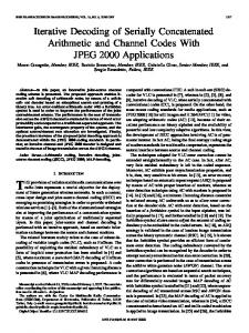
In this paper, we have studied how backward compatible performance improvement can be achieved using iterative decoding in selected existing wireless communication and digital recording systems. Concatenated codes and iterative decoders were first described using composite mappings, so that various applications could be treated using a uniform notation. A novel AZD based iterative decoder was also introduced for concatenated systems where turbo decoding cannot be used. As simulation results have shown, decoding gain of up to several dB can be achieved with a relatively small increase in receiver computational complexity, since most of the decoding improvement is achieved within the first three to four iterations. The gains can be used to achieve faster data read-out, lower receiver cost or better coverage in the systems we studied. REFERENCES [1] W. W. Peterson and E. J. Weldon, Error-Correcting Codes. Cambridge, MA: MIT Press, 1972. [2] R. G. Gallager, Low-Density Parity Check Codes. Cambridge, MA: MIT Press, 1963. [3] G. D. Forney Jr., Concatenated Codes. Cambridge, MA: M.I.T. Press, 1966. [4] C. Berrou, A. Glavieux, and P. Thitimajshima, “Near Shannon limit error correcting coding and decoding: Turbo codes (I),” in Proc. Int. Conf. Communications, Geneva, Switzerland, May 1993, pp. 1064–1070. [5] S. Benedetto, D. Divsalar, G. Montorsi, and F. Pollara, “Continuous MAP algorithms and their applications to decode parallel and serial code concatenations,” in Proc. ESA Int. Workshop DSP Techniques Applied to Space Communications, Barcelona, Spain, Sept. 1993, pp. 8.10–8.24. [6] A. Picart, P. Didier, and A. Glavieux, “Turbo-detection: A new approach to combat channel frequency selectivity,” in Proc. Int. Conf. Communications, Montreal, Québec, Canada, June 1997, pp. 1498–1502. [7] E. K. Hall and S. G. Wilson, “Design and analysis of turbo codes on Rayleigh fading channels,” IEEE J. Select. Areas Commun., vol. 16, pp. 160–174, Feb. 1998. [8] T. Richardson, A. Shokrollahi, and R. Urbanke. Design of provably good low-density parity check codes. [Online] preprint. Available: http://cm.bell-labs.com/cm/ms/former/tjr/papers/degree.ps
890
IEEE JOURNAL ON SELECTED AREAS IN COMMUNICATIONS, VOL. 19, NO. 5, MAY 2001
[9] R. Steele, Ed., Mobile Radio Communications. New York: IEEE, 1995. [10] M. P. C. Fossorier, F. Burkert, S. Lin, and J. Hagenauer, “On the equivalence between SOVA and Max-Log-MAP decoding,” IEEE Commun. Lett., vol. 2, pp. 137–139, May 1998. [11] H. Kobayashi and J. Bajcsy, “System and method for error correcting a received data stream in a concatenated system,” Invention disclosure July 1996, US Patent 6 029 264, Feb. 2000. [12] H. Kobayashi and D. T. Tang, “On decoding of correlative level coding systems with ambiguity zone,” IEEE Trans. Commun., vol. COM-19, pp. 467–477, Aug. 1971. [13] J. Bajcsy, “Iterative decoding in concatenated systems,” Ph.D. dissertation, Dept. of Electrical Engineering, Princeton University, Princeton, NJ, Nov. 1999. [14] N. Alon, J. Edmonds, and M. Luby, “Linear time erasure codes with nearly optimal recovery,” in Proc. 36th Annu. Symp. Found. Computer Science, Milwaukee, WI, Oct. 1995, pp. 512–519. [15] M. G. Luby, M. Mitzenmacher, M. A. Shokrollahi, D. A. Spielman, and V. Stemann, “Practical loss-resilient codes,” in Proc. 29th Annu. ACM Sympo. Theory of Computing, El Paso, TX, May 1997, pp. 150–159. [16] M. Umemoto, Y. Eto, and T. Fukinuki, “Digital video recording,” Proc. IEEE, vol. 83, pp. 1044–1054, July 1995. [17] K. A. S. Immink, “The digital versatile disc (DVD): System requirements and channel coding,” SMPTE J., vol. 105, pp. 483–489, Aug. 1996. [18] S. B. Wicker and V. K. Bhargava, Eds., Reed–Solomon Codes and Their Applications. New York: IEEE Press, 1994. [19] H. Kobayashi, “A survey of coding schemes for transmission or recording of digital data,” IEEE Trans. Commun. Technol., vol. COM-19, pp. 1087–1100, Dec. 1971. [20] B. H. Marcus, P. H. Siegel, and J. K. Wolf, “Finite-state modulation codes for data storage,” IEEE J. Select. Areas Commun., vol. 10, pp. 5–37, Jan. 1992. [21] H. Kobayashi, “Application of probabilistic decoding to magnetic recording systems,” IBM J. Res. Develop., vol. 15, pp. 64–74, Jan. 1971. [22] F. J. MacWilliams and N. J. A. Sloane, The Theory of Error Correcting Codes. Amsterdam, Holland: North-Holland, 1977. [23] W. Ryan, L. McPheters, and S. McLaughlin, “Combined turbo coding and turbo equalization for PR4-equalized Lorentzian channels,” in Proc. Conf. Information Science and System, Princeton, NJ, Mar. 1998, pp. 489–493. [24] T. Souvignier, M. Öberg, P. H. Siegel, R. E. Swanson, and J. K. Wolf, “Turbo decoding for partial response channels,” IEEE Trans. Commun., vol. 48, pp. 1297–1308, Aug. 2000. [25] H. Song, V. Kumar, E. Kurtas, and Y. Yuan. Turbo decoding for optical data storage. presented at Int. Conf. Communications. [Online] [26] H. Nickl, J. Hagenauer, and F. Burkert, “Approaching Shannon’s capacity limit by 0.27 dB using Hamming codes in a ‘turbo’-decoding scheme,” in Proc. Int. Symp. Information Theory, Ulm, Germany, June/July 1997, p. 12. [27] D. Chase, “A class of algorithms for decoding block codes with channel measurement information,” IEEE Trans. Inform. Theory, vol. IT–18, pp. 170–182, Jan. 1972. [28] R. M. Pyndiah, “Near-optimum decoding of product codes: Block turbo codes,” IEEE Trans. Commun., vol. 46, pp. 1003–1010, Aug. 1998. [29] G. Gaskill and K. Gray, SEIKO High-Speed Subcarrier Data System (HSDS): Seiko Telecommunication Systems, Inc., 1993. [30] J. Bajcsy and H. Kobayashi, “Good interleavers for concatenated finite shift register codes,” in Proc. Int. Symp. Information Theory and Applications, Mexico City, Mexico, Oct. 1998, pp. 327–330.
Jan Bajcsy (S’94–M’00) received the B.Sc. degree in engineering from Harvard University, Cambridge, MA, in 1994, and the M.Sc. and Ph.D. degrees in electrical engineering from Princeton University, Princeton, NJ, in 1997 and 1999, respectively. He is currently an Assistant Professor with the Department of Electrical and Computer Engineering, McGill University, Montreal, QC, Canada. His research focuses on channel coding, wireless communication systems, and optical signal processing.
Chan-Vee Chong (S’00) received the B.Sc. degree in electrical engineering from Princeton University, Princeton, NJ, in 1998 as a class Valedictorian. He will receive the M.Sc. degree from the Massachusetts Institute of Technology, Cambridge, MA, in June 2001. From June till August 2000, he worked as a summer intern with the Wireless Access Laboratory, NTT DoCoMo, Yokosuka, Japan.
D. A. Garr photograph and biography not available at the time of publication.
J. Hunziker photograph and biography not available at the time of publication.
Hisashi Kobayashi (S’66–M’68–SM’76–F’77) received the B.S. and M.S. degrees in electrical engineering from the University of Tokyo in 1961 and 1963, respectively. He received the Ph.D. degree from Princeton University, Princeton, NJ, in 1967. He was a radar system designer at Toshiba Electric Co., Tokyo, Japan, from 1963–1965. He was with the IBM Research Division, Yorktown Heights, NY, and Tokyo, from 1967 until 1986. From 1982 to 1986, he was the founding Director of IBM Tokyo Research Laboratory, Tokyo, and directed many research projects in computer science and engineering. In 1986, he joined Princeton University as Sherman Fairchild University Professor of Electrical Engineering and Computer Science, and as Dean of the School (1986–1991). He held visiting professorships at University of California, Los Angeles (1969–1970), University of Hawaii, Honolulu (1975), Stanford University, Stanford, CA (1976), Technical University of Darmstadt, West Germany (1979–80), University of Brussels, Belgium (1980), the University of Tokyo, Japan (1991–1992) and the University of Victoria, Canada (1998). His research interests are in the areas of coding and modulation for wireless communication, high-density digital recording systems, modeling and performance analysis of high-speed, and all-optical communication networks. Dr. Kobayashi received the Humboldt Award from West Germany in 1979, the IFIP Silver Core Award in 1980, and elected a Member of the Engineering Academy of Japan in 1992. He is a member of ACM, IPSJ (Information Processing Society of Japan), and IEICE (Institute of Electronics, Information and Communication Engineers) of Japan.