WSEAS TRANSACTIONS on SYSTEMS and CONTROL
Marwan A., Farrukh Nagi, Ksm Sahari, Hanim S., Fadi. I.
On-Line Adaptive Fuzzy Switching Controller for SCARA Robot MARWAN A., FARRUKH NAGI, KSM SAHARI, HANIM S., FADI. I. Department of Mechanical Engineering Universiti Tenaga Nasional Jalan IKRAM-UNITEN, Kajang, 43000, Selangor MALAYSIA
[email protected],
[email protected],
[email protected],
[email protected]
Abstract: - This paper presents the design, development and implementation of a new on-line adaptive MIMO switching controller (FSC) for real-time tracking control of an industrial SCARA robot. Two link SCARA robot is a nonlinear plant. The fuzzy control is based on the Takagi-Sugeno’s type fuzzy architecture model with on-line self-tuning so that both the desired transient and steady state responses can be achieved at different operation conditions. The online real-time self-tuning is based on the gradient steepest descent method, which tunes the inputs and outputs scaling factors of the proposed fuzzy controller. This controller simplifies the Real-time control implementation and improves the control performance. Real-time controller is implemented in Matlab’s xPC Real-time workshop environment. SCARA robot system identification was accomplished by using Auto Regression with external input method (ARX) to determine the discrete time transfer function necessary for the controller design. Comparison between the self-tuned fuzzy switching controller and fixed fuzzy switching controller was made to evaluate the real time tuning’s performance. The comparison is based on the tracking ability subjected to large payload. Based on the real time results the performance of fuzzy switching controller with this tuning strategy was found to be superior and it matches favourably to the operating conditions.
Key-Words: - SCARA robot ; two-link manipulators; fuzzy switching control; online self-tuning; xPC Target; educational robotics. for nearly two decades [8]. Some of these are in spacecraft satellite attitude control systems [9], the servo systems VIA [10], control of water tank system [11], in the reduction of harmonic current pollution [12], crane hosting and lowering operation [13], the elevator control [14] and in process control valves operation [15]. Fuzzy switching controller has become a popular tool after these successful applications. Recently, many analysis results and design methodologies of fuzzy control have been reported. However, most of these reported research only focused on single-input-single-output (SISO) systems. The main difference between Multiple-Input Multiple-Output (MIMO) control systems and SISO control systems is in the means of estimating and compensating for the interaction between higher degrees of freedom systems. MIMO systems usually posses complicated dynamics coupling. Estimate of accurate dynamic model and decoupling it for designing the controller is difficult. Hence the traditional model-based SISO control scheme is hard to implement on complex MIMO systems because of high computational burden. Therefore,
1 Introduction A SCARA robot manipulator is multivariable nonlinear coupling dynamic system with uncertain elements such as friction. The manipulators are usually used to perform high-precision tasks and by controlling the motion of a robot effectively and accurately. Efforts have been made in developing control schemes to achieve the precise control of SCARA robot manipulators [1, 2, 3, 4, 5, 6 and 7]. Among the available options, fuzzy control has the greatest potential since it is able to compensate the system’s dynamics with human’s initutiue control behaviour. In control theory, on-off controller switches abruptly between two states. They are often used to control a plant that accepts a binary input, for example a furnace that is either completely on or completely off. Most common residential thermostats are switching controllers. The Heaviside step function in its discrete form is an example of on-off control signal. Artificial intelligence technique such as fuzzy logic has provided the means to develop flexible fuzzy switching controller. Fuzzy Switching Controller (FSC) has been successfully applied in various areas
ISSN: 1991-8763
404
Issue 11, Volume 6, November 2011
WSEAS TRANSACTIONS on SYSTEMS and CONTROL
Marwan A., Farrukh Nagi, Ksm Sahari, Hanim S., Fadi. I.
the model-free fuzzy control strategy is gradually attracting attention. However, the number of control rules and controller computational burden grow exponentially with the number of input variables considered [5]. Clearly, the difficulty in controlling MIMO systems is to solve multi degree freedom coupling effects. Thus, an appropriate coupling fuzzy controller is incorporated into a TakagiSugeno’s fuzzy architecture to control these systems. In this study on-line tuning method for the TS fuzzy controller was investigated for robust control of SCARA robot. Inputs and outputs of controller were tuned with gain factor. Scaling I/O gains factors have critical effect on the response of the fuzzy controller and they are easier to tune. Passino and Yurkovich [16] stated that tuning of error input gain has effect of changing the loop-gain which results in overshoot, while tuning of input- change in error results in altering the derivative gain which affects the transient response of the system such as settling and rise time. The scaling factor of output MF’s has effect on increasing the saturation level of the controller output. Maeda and Murakami [17] proposed a self-tuning algorithm of the fuzzy logic controller, which has two functions. First, it adjusts the scaling factors of the fuzzy logic controller. Secondly, it improves the control rules of the fuzzy logic controller by evaluating the control response in real time. Demaya et al. [18] discussed in details the effects of tuning SF and MF. They argued that SF has more profound effect than MF tuning and SF should be used for coarse while MF for the finetuning of the response. Here, for tuning of the proposed fuzzy switching controller inputs and outputs scaling factors, steepest descent method which is also known as the Gradient Descent method was used. Gradient descent method is basically an optimization algorithm to find the local minimum of a function [19]. Gradient Descent method is widely popular among the mathematicians and physicists due to its easy concept and relatively small work steps. The proposed fuzzy rule base is used for the computation of the gradient step in which it is adjusted continuously with respect to the amount of variation of the performance criterion and the direction of the gradient vector of the fuzzy controller parameters [20]. It is not hard to see why the method of steepest descent is so popular among mathematicians, because of its simplicity and iterative approach. But the biggest advantage of this method lies in the fact that it is guaranteed to find the minimum through numerous times of iterations as long as it exists.
ISSN: 1991-8763
System identification is widely used in engineering and non engineering areas [21]. The system identification helps to construct system’s mathematical from experimental data. The robot should be represented in its mathematical model in order to be able to study the behaviour and to design a controller for the robot. Through the Auto Regression with external input method (ARX), discrete time transfer function can be determined to identify the dynamics of real SCARA robot manipulators. For system identification of robots, it is necessary to know the output position of each joint and the robot’s actuation signal. From a practical viewpoint, the ARX models are the most suitable candidates for parameter estimation. However, in multivariable systems, the identification of high order ARX models would require more data points. For higher order ARX models parsimonious parameterization is used [22]. The controlling technique described in this paper is different from the previous works. First, the fuzzy structure is different. The fuzzy model based on Takagi-Sugeno’s model, uses tuning of output gains function. However, due to fixed bi-level output of switching action, an output gain parameter is used. Secondly, the self tuning technique is used which is based on a simple gradient descent method for MIMO fuzzy switching controller. Thirdly, the tuned controller design is based on compensation of steady state error and reduction of cross coupling effects and as well as on the improvement of settling time. In most tuning applications isosceles triangular membership functions are used with TSK or Mamdani model. Commonly, centre of area (COA) defuzzification for Mamdani model is used for tuning. In this paper a different defuzzification, largest of maxima (LOM) is used to arrange the output function in a certain way to rend switching output from the controller. A major practical advantage of LOM switching controls is that they can be implemented with simple on-off action. The control output takes on either minimum or maximum value to yield minimum-time control of the system. Finally, for low cost and reliable solutions with high levels of flexibility the design controller is implemented in real-time workshop [23]. In this paper, the proposed controller consists of sets of linguistic rules. The consequent part of the fuzzy rules has only two linguistic values, while the premise parts are freely chosen. It is structurally simple due to two member functions in its fuzzy output set and rule matrix. An important feature of FSC is its flexibility and its optimal time response, which is independent of initial conditions.
405
Issue 11, Volume 6, November 2011
WSEAS TRANSACTIONS on SYSTEMS and CONTROL
Marwan A., Farrukh Nagi, Ksm Sahari, Hanim S., Fadi. I.
The rest of the paper is organized as follows. In section 2, mathematical model is studied to demonstrate the SCARA robot control system. System identification is presented in section 3. The structure of the proposed controller is presented in section 4. Section 5 shows the simulation results and its discussion. Section 6, shows the experimental setup and system performances. Finally, conclusion is presented in section 7.
The elements in the above equation have been calculated as follows. q q 1 1 , 1 q 2 2 2 M11 J1 J 2 m1r12 m2l12 m2 r22 2m2l1r2 cos q2 mLl12 mLl22 2mLl1l2 cos q2
M 12 J 2 m2 r22 2m2 l1r2 cos q2 mL l 22 mL l1l 2 cos q2 M 21 J 2 m2r22 m2l1r2 cos q2 mLl22 mLl1l2 cos q2
M 22 J 2 m2 r22 mL l 22
2. MATHEMATICAL MODEL OF TWO-LINK TYPE OF A SCARA ROBOT
V1 (m2l1r2 mLl1l2 )(2q1 q2 )q2 sin q2 V2 (m2l1r2 mLl1l2 )q2 sin q2
U 1 b1 1 b1 q1
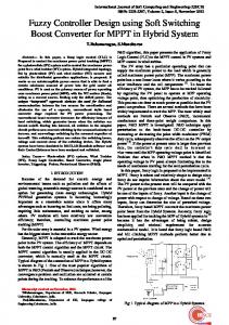
In this section, we illustrate the mathematical model of a two-joint type SCARA robot [24]. For the following robot model the links masses are nonconcentrated at the centres of the arm. Hence, each link has different moments of inertia and there are frictions in the joints. Table 1 shows the parameters of the two-link rigid -type robot. The mechanical model of a robot manipulator is shown in Fig.1
U 2 b22 b2q2
W1 (m1 gr1 m 2 gl1 m L gl1 ) sin q1 (m2 gr2 m L gl 2 ) sin(q1 q 2 )
W1 (m2 gr2 m L gl 2 ) sin(q1 q 2 )
The control is given by FSC, hence M (q) u N (q, q )) Where:
(2)
V U 1 W1 N (q, q ) 1 V2 U 2 W2
Under the FSC control; that is Fig. 1 SCARA robot’s Link 1 and Link 2
M (q) 1 ( N (q, q )) q
Table 1. Parameters of the two-link rigid type robot Parameters link 1 m1 1.35 Kg J1 3222 Kg cm
3. System Identification
Parameters link 2
System or process identification is renders mathematical structure of systems (processes) from experimental data. The input-output data obtained from experiment contains information about the system properties that are of interest to the user. In this work we test the open loop response of SCARA robot link1 and link2 under square wave input signal. The links response for square wave input is shown in Fig.2.
m2 1.40 Kg 2
l1 25 cm r1 12 cm b1 2 Kg cm s
J1 4059 Kg cm2 l1 27 cm r1 13 cm
b1 4 Kg cm s
mL [0.5,1] Kg
The dynamic equation of the SCARA robot manipulator is defined below: M 11 M 21
1 V1 U 1 W1 1 M 12 q 2 V2 U 2 W2 2 M 22 q
(1)
where q is the generalized coordinate vector is the generalized force vector M ( q ) is the inertia matrix V ( q , q ) is the Coriolis/centripetal vector W ( q ) is the gravity vector U ( q ) is the friction vector
ISSN: 1991-8763
Fig. 2 Open Loop Response Link1& Link2 of SCARA Robot
406
Issue 11, Volume 6, November 2011
WSEAS TRANSACTIONS on SYSTEMS and CONTROL
Marwan A., Farrukh Nagi, Ksm Sahari, Hanim S., Fadi. I.
Among different kind of MATLAB System Identification Toolbox model’s validation the Auto Regression with external input method (ARX) is chosen to identify the dynamics of real SCARA robot manipulators. It is necessary to know the position output of each joint and the robot’s actuation signal. Discrete Transfer function from input "u1" to output "y1" for link1 presented in Equation (4).
of the controller and X i is the universe of discourse of the four inputs. For input variable, x1 = “error angle for link 1”, x2 =”error angle for link 2”, the universe of discourse, X i 1,2 = [-2000, 2000] deg, which represents the range of perturbation angle about the zero reference. For input variable x3 =“error angle rate for link 1”, and x4 =“error angle rate for link 2”, the universe of discourse x3 = x4 = [-1.333e+e004, 1.333e+004] deg. The output universe of the Takagi-Sugeno’s discourse u j = [-1, 1] represents the bang-bang output Where
(4)
G1
Transfer function from input "u2" to output "y2" for link2 presented in Equation (5).
j 1,2
is the output index of the controller. The ~k linguistic variable A i is the membership function of antecedent part defined as ~ ~1 =LN, ~ 2 =LP] (6) Aik =[ A Ai i
(5)
G2
4. The Proposed Controller Structure
Where, Index k is assigned to tally the linguistic input membership functions and Index i is assigned to tally the input variables. Similar values are selected for inputs xi 1,2 ,3,4 where the membership ~ ~ ~ ~ functions are assigned as A1k A2k A3k A4k . The set k B which denotes the membership function values for outputs variable u j are defined as:
The MIMO fuzzy switching controller is reviewed in this section. And, a special type of membership functions, the complement type is defined. The ranges input and output variables are necessary for any fuzzy controller, which are considered to be a reasonable representation of situations that controller may face and yield to stability of the controller, the structure of proposed controller with the self-tuning scheme shown in Fig.3.
B1 B2 B kj = [ 1 →Nbang1, 1 →Pbang1] B1 B3 B kj = [ 2 → Nbang2, 2 →Pbang2]
(7)
Where, Index k is assigned to tally the input membership functions. j =1, 2 is the output index of the controller for the robot manipulators link 1 and link 2, respectively, the two levels switching ycrisp output shown in Fig.4.
Fig. 4 Two levels switching y crisp output.
Fig. 3 The structure of fuzzy switching controller with the on line self-tuning scheme
4.2 Fuzzy Rules The fuzzy switching linguistic rules assembled in this work reset the robot manipulators to the desired position. These rules are based on four inputs variables, each with three linguistic values are defined as (LN, Z, and LP). Where LN = Large Negative, LP = Large Positive, thus there are at most (N= 34) possible rules. The tuning rules-
4.1 Linguistic Description The input and output parameters, as well as the partitions and spread of the controller membership functions are initially selected to match the dynamic response of a robotics manipulator system. The inputs xi Є X i , where i 1,2,3,4 is the input index
ISSN: 1991-8763
407
Issue 11, Volume 6, November 2011
WSEAS TRANSACTIONS on SYSTEMS and CONTROL
Marwan A., Farrukh Nagi, Ksm Sahari, Hanim S., Fadi. I.
partitions are heuristically chosen to reset the links smoothly over the universe of discourse. The surface for the rules of the FBBC for MIMO is shown in Fig.5. These rules can be illustrated as a representation of the matrix (34×3) (the number of membership function is depicted. The main diagonal entry in the rules given in Table 2 is not used. The tuning rules-partitions are heuristically chosen to reset the links smoothly over the universe of discourse.
μ
B i
(y ) μ k ( x ) n i A i, j
μ
(x ) i 1 i 1, j
(8)
Ak
where i=1,2,3,4 is the input index of the controller and j= 1, 2, 3, 4,….N , is the index of N matching rules, which are applicable from inferences of inputs. N=1, 2 is the output index of the system.
4.3 Fuzzy Set Membership Functions The input variables and values assigned to fuzzy set membership functions are shown in Fig.6. Triangular shape membership functions are used in this work. These membership functions are sensitive to small changes that occur in the vicinity of their centres.
(a) Fig. 6 The input variables and values assigned to fuzzy set membership functions. A small change across the central membership 2
function A i , located at the origin, can produce abrupt switching of control command u j between the +ve and –ve halves of the universe of discourse, resulting in chattering. The overlapping of the central membership function membership function A i2 with the neighbouring membership
(b) Fig. 5 Viewer Surface of the Controller’s Rules: (a) First Output (b) Second Output.
functions A i1 and A i3 reduce the sensitivity of the bang-bang control action where, i=1,2,3,4 is the input index of the controller. Triangular membership functions in Fig.7 are based on mathematical characteristics given in Table 3. In Table 3, the ai and bi are the parameters for range and central location of membership functions respectively, where i=1, 2, 3, 4 is the input index of the controller and shown in Fig.8. Smooth transition between the adjacent membership functions is achieved with higher percentage of overlap, which is commonly set to 50%.
Table 2. Fuzzy Rules of the Switching Controller
The symmetry of the rules matrix is expected as it arises from the symmetry of the system dynamics. Minimum decomposition of linguistic rules from the fuzzy switching controller’s inputs to the outputs is described in the following equation.
ISSN: 1991-8763
408
Issue 11, Volume 6, November 2011
WSEAS TRANSACTIONS on SYSTEMS and CONTROL
Table 3. Mathematical Characterization Triangular Membership Functions
Marwan A., Farrukh Nagi, Ksm Sahari, Hanim S., Fadi. I.
of
The online self-tuning mechanism is shown in Fig.9, heading error, e (k), and change of heading error, eΔ(k) , are determined as follows:
Linguistic value Triangular Membership functions Aik 1
Aik 2
Aik 3
i Ai1( xi ) 1
1 2 x ai bi
2 xi ai 1 bi 1 2 xi ai bi
i Ai2 ( xi )
2 xi ai 1 bi 1
i Ai3( xi )
e (k) = yr(k) - y(k)
x bi
eΔ (k) = e(k) – e (k-1)
bi xi ai
(10)
where yr (k) is the command reference and y (k) is the actual output response. The self-tuning method of the proposed controller applies double gradient descent block technique each one tunes one of the controller’s outputs. The proposed controller is tuned by minimizing a cost function. The cost function is defined as the difference between the actual heading and the reference command as expressed in equation (11).
ai xi 0 0 xi ai ai x bi xi bi
f
4.4 Online Self-Tuning Control performance of a system can be improved by tuning the controller scale factor. The proposed tuning method in this paper adjusts the heading reference command of the controller instead of directly adjusting the controller gains. The tuning method uses the gradient descent method to tune the fuzzy gains values. The originality on this proposed method is the use of the fuzzy switching controller together with the online self-tuning to control the direction of the robot’s manipulators. The steady state error is eliminated online during the robot work. The decoupling effect of the control axis is also reduced. It is an adaptive control, since with the change in robot dynamics changes, the control system tune itself and adapt to the changes in the plant’s dynamics. The method of steepest descent (also known as the gradient method) is the simplest example of a gradient based method for minimizing a function of several variables, the block diagram of the online self tuning shown in Fig.7.
e(k ) g (k )
(11)
Substitute equation (10) in (11) yield e(k 1) e(k ) G
e(k ) g (k )
(12)
The search starts at an arbitrary point e0 and then slide down the gradient, until we are close enough to the suitable gains. Obviously, we need to move to the point where the function f→e takes on a minimum value, by using descent gradient method update of g (k 1) g (k ) G
E (k ) g (k )
(13)
where, e(k), e(k+1) = values of the error variables in the k and k+1 iteration. ƒ(k) = The choice of direction function to be minimized. Δƒ= gradients of the objective function, constituting the direction of travel. G = the gradients step size. g (k ) =is the gain of the output point of the gradient. Δ g (k ) =the deference of the output point gain’s reference command. The method of Steepest Descent is simple, easy to apply and each iteration is fast. Is it also very stable; if the minimum points exist, the method is guaranteed to locate the suitable gains values after a few number of iterations [8].
Fig. 7 Block Diagram of the Online Self-Tuning
ISSN: 1991-8763
(9)
409
Issue 11, Volume 6, November 2011
WSEAS TRANSACTIONS on SYSTEMS and CONTROL
Marwan A., Farrukh Nagi, Ksm Sahari, Hanim S., Fadi. I.
5. Simulation Results The performance of the proposed controller is evaluated in a variety of operating conditions. The controller algorithm is housed inside the personal computer with Pentium-IV processor and all numerical values of the simulation model are obtained by system identification technique presented in section.4. The software environment used for these simulation experiments is MATLAB Ver.2010b, with Simulink package and 0.001 kHz discrete sample time. Many simulation tests were performed in order to compare the performances of the proposed controller with and without real time self-tuning for different operating conditions.
5.1 Fixed Fuzzy without Tuning
Switching
(c) Fig. 8 Fixed Fuzzy Switching Controller: (a) Output response of Link1 and Link2. (b) MIMO Controller Action for Link1. (c) MIMO Controller Action for Link2.
5.2 Fuzzy Switching Controller with Tuning
Controller
Apply tuning to fuzzy switching controller demonstrate good results as shown in Fig.9. It can be seen from the figures that both convergence time and angles errors are minimized by applying tuning to the controller.
In this section, fixed fuzzy switching controller output response of link1 and link2 and, MIMO controller action for link1 and link2 are showing in Fig.8. From Fig (8 a) it can be observed that fuzzy switching controller without tuning provides constant speed even under sudden change in load condition. The steady state error for the fixed switching controller is large even at zero payload. Firing actions of the outputs controller for both links are shown in Figs (8 a) and Fig (8 b) respectively. It can be concluded that the conventional fuzzy bangbang controller will not be able to provide a good control performance without the real-time tuning algorithm.
(a)
(b)
(a)
(c) Fig.9 Real Time Tuned Fuzzy Switching Controller: (a) Output response of Link1 and Link2. (b) MIMO
(b)
ISSN: 1991-8763
410
Issue 11, Volume 6, November 2011
WSEAS TRANSACTIONS on SYSTEMS and CONTROL
Marwan A., Farrukh Nagi, Ksm Sahari, Hanim S., Fadi. I.
Controller Action for Link1. (c) MIMO Controller Action for Link2.
multifunction I/O boards. However, the use of RTW still requires the development of custom interface problem, xPC Target is included in the software configuration. The xPC Target software supports and provides built-in drivers for many industry standard DAQ card including the PCI-6024E DAQ card by National Instrument which is used in the prototype of the SCARA robot system. A personal computer is used as host computer. Windows operating system and other required software are running in the host computer. Simple on-off control requires low cost switch motor drivers which receive command from xPC controller. The motors and other components setup are shown in Table.4. The EM14 Incremental encoders produce quadratics output via two channels A&B which are used to detect the angle motion and direction of the links. The encoder output 64 pulse/sec which is increased to 256 pulse/sec using gear ratio of 3.5.
From the simulation results above we conclude that, the fuzzy switching controller provide satisfactory tracking performance with gradient steepest descent tuning method even under sudden change in load condition.
6. Implementation And Results 6.1 Experimental Setup In order to evaluate the performance of the proposed controller, it is used to control two-link SCARA robot. The overview of the system set-up is shown in Fig.10. The fuzzy controller is implemented digitally on a personal computer and is operated with 0.001ms sampling time. The MathWork’s MATLAB/Simulink is used for realtime controller implementation through RTW and xPC Target. The RTW environment provides a realtime operation using personal computers and
Fig. 10 Overview of system set-up
No 1.
2. 3. 3. 4. 5.
ISSN: 1991-8763
Table 4. Hardware component system set-up Part Name Brand Name DAQ/6024E I/O Device for PCI, NATIONAL PXI, Compact PCI, and PCMCIA INSTRUMENTS Bus PCs. FDO4A Flexibot Driver CYTRON EM14-14mm BOURNS Rotary Optical Encoder Communication cable RS232 ANY DC-Micromotor FAULHABER Series(2642..CR)12V.DC Gearheads Series:(1/66) reduction FAULHABER
411
Parts No 1 1 2 1 2 2
Issue 11, Volume 6, November 2011
WSEAS TRANSACTIONS on SYSTEMS and CONTROL
Marwan A., Farrukh Nagi, Ksm Sahari, Hanim S., Fadi. I.
Experimental studies were carried out to evaluate the performance of adaptive FSC in two parts. The first part is to test the trajectory tracking capability of the fuzzy switching controller with different payload and under real-time tuning. In second part the performance of the fixed fuzzy switching controller with different payloads and without tuning strategy was tested. The test is to evaluate the tuning effect on the performance of the proposed controller under different conditions. The overview real-time experiment is shown in Fig.11.
The proposed controller is developed in Simulink using its blocks and Fuzzy Logic Toolbox, and then it is built so that C code is generated, compiled and finally a real-time executable code is generated and downloaded to the Target Computer. The Simulink model of the proposed control system for Link1 and Link2 of the SCARA is shown in Fig.12. Using this model, iterative tuning is performed on the input and parameters of the proposed controller. The aim is to achieve zero overshoot within an acceptable steady-state error in tracking input.
Fig. 11 Overview Real-Time Experiment
Fig. 12 Overall xPC Target MATLAB-Simulink for Fuzzy Switching Controller with online tuning
ISSN: 1991-8763
412
Issue 11, Volume 6, November 2011
WSEAS TRANSACTIONS on SYSTEMS and CONTROL
6.2
Marwan A., Farrukh Nagi, Ksm Sahari, Hanim S., Fadi. I.
performance of tracking control system was evaluated based on overshoot and steady state error. The analyses were carried out on tracking and step inputs. The control outputs in the Figs 13 to 18 show the changes made in gains to adjust the response for minimum overshoot and steady state error.
System Performances
The performance of the proposed fuzzy switching controller was compared experimentally with and without the adaptive tuning effect which is designed and discussed in section 4.4. The detailed performance comparison is shown in Table.5 with referenced figures indicated in the table. Here, the
Table 5. Comparison of the proposed controller Tracking 90⁰ Sine Wave Input Signal with and without Tuning FSC With Tuning Load (Kg)
Overshoot (Degree)
Steady State Error (Degree)
0
1.5
0.5 1
FSC Without Tuning
Fig.No
Overshoot (Degree)
Steady State Error (Degree)
Fig.No
1.7
16 a
16
11
13 a
4.8
2.6
17 a
55
26
14 a
6.7
4.8
18 a
12
31
15 a
The table manifests the robustness of the adaptive capabilities of the controller, by minimizing the overshoot and steady state error. The fixed an untuned controller has constant unit output as shown in Fig 16 to Fig 18. In comparison the adaptive controller of links in Fig 13 to Fig 15, shows greater switching ability to compensate for higher loads and desired performance. In general, it can be concluded that the proposed adaptive fuzzy switching controller was successfully controlled the system’s links and it is better than the fixed fuzzy controller in tracking desired signal with different payloads.
(b)
(c) Fig. 13 Tuned Fuzzy Switching Controller with 0kg payload: (a) Output response of Link1 and Link2. (b) MIMO Controller Action for Link1. (c) MIMO Controller Action for Link2.
(a)
ISSN: 1991-8763
413
Issue 11, Volume 6, November 2011
WSEAS TRANSACTIONS on SYSTEMS and CONTROL
Marwan A., Farrukh Nagi, Ksm Sahari, Hanim S., Fadi. I.
(a)
(c) Fig. 15 Tuned Fuzzy Switching Controller with 1kg payload: (a) Output response of Link1 and Link2. (b) MIMO Controller Action for Link1. (c) MIMO Controller Action for Link2.
(b)
(a)
(c) Fig. 14 Tuned Fuzzy Switching Controller with 0.5kg payload: (a) Output response of Link1 and Link2. (b) MIMO Controller Action for Link1. (c) MIMO Controller Action for Link2. (b)
(c) Fig. 16 Fixed Fuzzy Switching Controller with 0kg payload: (a) Output response of Link1 and Link2. (b) MIMO Controller Action for Link1. (c) MIMO Controller Action for Link2.
(a)
(b)
ISSN: 1991-8763
414
Issue 11, Volume 6, November 2011
WSEAS TRANSACTIONS on SYSTEMS and CONTROL
Marwan A., Farrukh Nagi, Ksm Sahari, Hanim S., Fadi. I.
(c) Fig. 18 Fixed Fuzzy Switching Controller with 1kg payload: (a) Output response of Link1 and Link2. (b) MIMO Controller Action for Link1. (c) MIMO Controller Action for Link2.
(a)
7. Conclusion A MIMO fuzzy switching Controller suitable for real-time industrial applications has been successfully designed, developed and implemented in this paper. The approach of xPC target was adopted to shorten the development time, thus reducing the cost of development. Experimental results show that the proposed controller is able to control dynamics of the SCARA quickly and reduce the tracking error. SCARA robot system identification was accomplished by using Auto Regression with external input method (ARX) and discrete time transfer function was used for design of the new controller. The performance of the FBBC controller was found to be good and robust in the presence of high payload and it matches favourably with both the experimental and the simulated response. Besides, input and output scale factor parameters could be modified in real time via gradient steepest descent method. The links trajectories are easily monitored via xPC target which facilitates the testing of controller under different input conditions. The tuned proposed controller shows promising result and will be proved very useful in other real-time industrial applications.
(b)
(c) Fig. 17 Fixed Fuzzy Switching Controller with 0.5kg payload: (a) Output response of Link1 and Link2. (b) MIMO Controller Action for Link1. (c) MIMO Controller Action for Link2.
References: [1] F. Lin, Robust control design: an optimal control approach, Wiley-Interscience Publishing, 2006, pp.297-316. [2] M.J. Er, M.T. Lim and H.S. Lim, Real-time hybrid adaptive fuzzy control of a SCARA Robot, Microprocessors and Microsystems, Vol. 26, 2002, pp. 449–461. [3] Marius C., Ilie B, Onisifor O.,Luminta P. and Florin G. , The simulation Hybrid Fuzzy Control of SCARA Robot, Wseas Transactions on systems and control, Vol.3, No.2, 2008 pp.105-141.
(a)
(b)
ISSN: 1991-8763
415
Issue 11, Volume 6, November 2011
WSEAS TRANSACTIONS on SYSTEMS and CONTROL
Marwan A., Farrukh Nagi, Ksm Sahari, Hanim S., Fadi. I.
[4] Mahdi S. A., Florin I. and Riad T., Kinematic Modelling and Simulation of a SCARA Robot by Using Solid Dynamics and Verification by MATLAB/Simulink, European Journal of Scientific Research, Vol. 37, No. 3, 2009, pp. 388-405. [5] Eftekharian A. A. and Sayyadi H., Design of Mixed Fuzzy-GA Controller for SCARA Type Robot, Proceedings of the IEEE/RSJ International Conference on Intelligent Robots and Systems, Beijing, China, pp. 2173-2178, 2006. [6] Aroca R.V., Tavares D.M., and Caurin G., SCARA Robot Controller Using Real Time Linux, Advanced intelligent mechatronics, IEEE/ASME international conference, 2007, pp. 1-6. [7] Shinya A., Masami K and Jun I., Position Control of 2-Link SCARA Robot by using Internal Model Control,Mem.Fac.Eng.Oka.Uni, Vol. 43,2009, pp. 49-54. [8] Farrukh N., Aidil A., A. Talip, J. Nagi, Marwan A., Tuning of a New Fuzzy Bang-bang Relay Controller for Attitude Control System, International Journal of Automation and Control, Vol. 5, No.2, 2011, pp. 97 - 118. [9] Thongchet S. and Kuntanapreeda S. A fuzzy– Neural Bang-Bang Controller for Satellite Attitude Control, Proc. of SPIE, Application and Science of computational intelligence IV, Vol. 4390, 2001, pp. 97-104. [10]S. Y. Chang, T.L. Huang and T.Y. Huang Fuzzy Bang-Bang Controller for servo Systems VIA Optimal Path Estimation Method, IEEE Catalogue, No. 95th 8025, 1995. [11] K. Tanaka, M. Sugeno, Stability analysis and design of fuzzy control systems, Fuzzy Set and Systems 45.pp. 135-156, 1992. [12]B. Mazari and F. Mefri, Fuzzy Hysteresis Control and Parameter Optimization of a Shunt Active Power Filter, Journal of Information Science and Engineering, Vol.21, 2005, pp. 1139-1156. [13] S.Yasunobu and S. Miyamoto, Automatic train operation by predictive fuzzy control, in: M. Sugeno(Ed.), Industrail Applications of Fuzzy Control, North-Holland, Amsterdam, 1985, pp. 1-18. [14] Fujitec F., Flex-8800 Series Elevator Group Control System, Fujitec Co., Ltd., Osaka, Japan, 1988. [15]Ushiyama R. and Walden H. Cold plate temperature regulation using fuzzy logic control, SAE Equation Society of Automotive Engineers Trans.,1991, pp. 1790-1801.
ISSN: 1991-8763
[16]K. M. Passino and S. Yurkovich., Fuzzy Control, Adddison-Wesley Longman Inc Publishing, 1998. [17]M. Maeda and S. Murakami, A self-tuning fuzzy controller, Fuzzy Sets and Systems, Vol.51, 1992, pp. 29–40. [18]B. Demaya, R. Palm and Serge Boverie, Multilevel Qualitative and Numerical Otimization of Fuzzy Controller, 4th IEEE International Conference on Fuzzy Systems, 1995. [19]A. H. Habbi and M. Zelmat, Fuzzy Logic Based Gradient Descent Method with Application to a P1-type Fuzzy Controller Tuning: New Results, 3rd International Symposium on Computational Intelligence and Intelligent Informatics IEEE ISCIII, Morocco March 2830, 2007, pp.93-97. [20] X. Wang, Method of Steepest Descent and its Applications Department of Engineering, University of Tennessee, Knoxville, TN 37996 November 25, 2008, pp1-5. [21]M. Li, C. Chen, W. Liu, Identification Based on MATLAB, Proceedings of the International Workshop on Information Security and Application, China,2009, pp 523-525. [22]Angeles J., Fundamentals of Robotic Mechanical System: Theory, Methods, and Algorithms, Third Edition. New York: Springe, 2006. [23] M. A. Natick, “Real-Time Workshop, RealTime Workshop User’s Guide” , The Math Works, Inc., 2004. [24] K. Sahari, K. H. Weng, Y. W. Han, A. Anuar, M. Z. Baharuddin and S. S. K. Mohideen, Design And Development Of A 4–Dof Scara Robot For Educational Purposes, Journal Technology, Vol. 54, 2011, pp. 193–215.
416
Issue 11, Volume 6, November 2011