emphasis on On-line Transient Stability Assessment (TSA), ... Training Simulator (DTS) environments for planning and .... (rad./s)'. CMs. 0 0 wulw). (m). 0. First Swing Stable contingency. 'Ir. CMS .... IEEE Budapest Power Tech'99, Aug.
On-line Transient Stability Constrained ATC Calculations Rene Avila Resales*, Daniel Ruiz-Vega**, Damien Emst** t, Mania Pavella**, Jay Giri * ESCA CORPORATION 1 1 120 NE 3 P Place Bellevue, WA 98004, USA Rene.rosales 0alstom.esca.cQm
*-TOM
**University of Libge. Department of Electrical Engineering Sart-Tilman B28. B-4000 Like, - Beldum Mania.P~~vella@u~ t Research Associate. FNRS
Abstract: Transient Stability Assessment, preventive control measures and dynamic A X calculations are addressed for the new deregulated EMS system. The combination of time domain analysis, SIME and Optimal Power Flow provide a reliable solution for future
TSA for the above considering the Study and DTS environments ATC Calculation considering Dynamic Security Constraints Preventive Control using an optimization technique.
transaction requirements and the current operating point. Keywords: power systems, stability, energy management system, security assessment 1. INTRODUCTION
In recent years utility companies have been required to functionally separate their power transmission, generation and energy marketing departments. This separation presents new challenges for those utilities, whose formerly vertically integrated operational model had evolved over many years. Utilities are demanding new tools that address the challenges of a competitive market, while providing the same reliable operations as a full Energy Management System (EMS) software. Specifically, utilities require new tools to address static and dynamic security power system challenges. Independent power producers, distributed generation, multiparty energy transactions, increased transaction volumes, and energy routing require system operators to put a greater emphasis on On-line Transient Stability Assessment (TSA), integrated Available Transfer Capability (ATC) Static and Dynamic calculations and Preventive Control. These automated, real-time capabilities are necessary to operate the system reliably and optimize the utilization of the transmission system. Companies can easily justify online implementation of TSA and the determination of preventive control actions for the operation of their power system.
Regarding time horizon, TSA must be evaluated to provide ATC and preventive measures for the following: Planning Horizon (hours, days, weeks, months) Operating Horizon (real-time and immediate future) 2. TRANSIENT STABILITY ASSESSMENT IN THE
EMS The TSA role in the EMS depends on the type of company. Two basic alternatives are described below.
2.1 On-line TSA for the Transmission Services Provider (TSP) Figure 1 is a functional overview of the TSP environment. The purpose of the ATC calculator is to manage available transfer capability information for the Open Access Same Time Information System (OASIS) Automation system. It calculates initial ATC values during periods of initialization or resynchronization. It also calculates changes to ATC values that result from new requests for transmission service. The ATC calculator in this context currently performs either a flow-based or a path-based method. Figure 1 shows that the ATC calculator supports data input from multiple sources, the Response Factor (RF) calculator using State Estimation (SE) information, the Resource Scheduling (RS), and TSA and VSA if available.
This paper describes functional aspects for online TSA integration with the EMS, the Study and the Dispatcher Training Simulator (DTS) environments for planning and current operation analysis.
Constraints
+
r-------------I
Voltage Security Assessment (VSA) is not the subject of this paper, but is however included in all figures to complete the EMS operation and control center picture. The following TSAEMS issues will be discussed in the following sections: 0
e
TSA and the Transmission Services Provider TSA and the Independent System Operator
0-7803-6420-1/00/$10.00 (c) 2000 IEEE
Figure 1 Transmission ServicesRovider
1291
Authorized licensed use limited to: Georgia Institute of Technology. Downloaded on April 15, 2009 at 11:02 from IEEE Xplore. Restrictions apply.
The ATC calculator evaluates ATC data for each constrained facility based on the Operating Horizon (solid lines), the Planning Horizon (dashed lines) and in some cases a study horizon.
TSA will include stability constraints in the market solvers for the required time horizon and interfaces with the Resource Commitment (RC), the Resource Scheduling (RS) and the Resource Dispatch (RD) applications.
When a request for transmission capacity is received, the ATC calculator computes new ATC data and sends the values for evaluation. Once evaluated, the new ATC values may be posted. ATC values are calculated in advance and for future transmission reservations considering two horizons.
RS is a function with a time horizon of 24 hours in hourly intervals. The results are fed into the EMS market database and TSA and RD will iterate to ensure dynamic security in this time frame.
The operating horizon which starts in the next hour covers the immediate short term. The planning horizon starts after the operating horizon and extends into the future. Transfer paths are used to evaluate stability limits and the information is sent to the ATC; a fast technique is required to update the limits when a specific request for transmission capacity reservation is received. Response Factor (RF) runs in real-time using fresh information from state estimation and currently calculates flow at each gate and the sensitivity of each flow gate to a new reservation on a given path. TSA Sensitivity values will be considered in the RF evaluation for the constrained facilities (related to the transfer path) to obtain ATC estimated values for future transactions.
RD typically executes every five minutes and its purpose is the real-time dispatch of the resources. It uses generator response and limits to calculate base points for AGC as well as unit participation factors. Figure 2 shows the Planning Horizon (dashed line) and the Current Operating loop (solid line) with TSA to include stability constraints. TSA can provide limits every five minutes, with a fast and reliable sensitivity approach. Several dynamic contingencies and transactions are evaluqted for real-time and planning scenarios. A fast and efficient dynamic screening methodology is described in the following sections that reduces the calculation and identifies the harmful contingencies.
Resource Scheduling (RS) uses resource commitment, network data, forecasted conditions, transaction information and device schedules to optimize and obtain transfer limits. TSA will include stability constraints as part of the calculation.
For the Planning Horizon, TSA will analyze contingencies and transactions for daily operation and up to two weeks in advance.
VSA and TSA reside in independent boxes and will use distributed processing to minimize execution time.
2.3 TSAfor the DTS and Study Environments
2.2. On-line TSA for the Independent System Operator (ZSO) Figure 2 describes an IS0 environment using a Resource Dispatch (RD) that provides solutions for the market based operation.
4
VSA and TSA reside in independent boxes and will use distributed processing to minimize execution time. The DTS provides a realistic environment for operators to practice normal, everyday operating tasks and procedures, as well as emergency conditions. It can be used in an experimental and investigatory manner to recreate past scenarios, or simulate future behavior of the system and the EMS. The DTS and Study environments should include RS, RD, VSA and TSA to emulate the new energy system. Remedial actions can be integrated as part of the simulation process, thereby providing for a powerful dynamic tool. The following features are required 0 0 0
0
Const”
i
Figure 2 Independent System Operator
0-7803-6420-1/00/$10.00 (c) 2000 IEEE
The DTS fast real-time initialization The Data Preparation (DP) using the DTS databases Network information, transactions, contingencies, monitored elements and parameters are sent to the TSA box TSA output is summarized and sent to the DTS to continue with the near future base-case condition
The DTS can be thought of as being parallel to, and a close emulation of the EMS environment. Hence, results in the DTS environment are highly reliable and accepted by the EMS users.
1292
The Study tools are shown with dashed lines in Figure 3 and its loop is similar to the DTS, except that it is primarily used for power flow case analysis including optimal power flow and contingency analysis. Study is initidized from real-time or save cases to recreate actual conditions and analyze the impact of “what if’ conditions to prevent dangerous sit
Figure 3 Study and DTS dynamic tools
3. CONGESTION MANAGEMENT In general the EMS should be provided with a set of optimization tools that will allow Congestion Management (CM) and generation redispatch. Preventive control is an example where TSA and these optimization tools can be used. The integration of the planning and the current operating horizons will force the extensive use of optimization not only for the next hour, but for the day and month ahead. TSA shall interface with these tools to analyze dynamic contingencies, then stabilize unstable cases, possibly via an OPF. The CM process will participate in activities like ATC calculation and response against security violations. These tools may be used to plan and schedule controls for dangerous situations. The controls will have of course associated cost of operation, and in some cases they could be cost free. CM tools shall be flexible and easy to use by different applications like VSA and TSA to consider dynamic and voltage problems.
RS and RD are part of the applications including optimization tools in new deregulated EMS. The following section describes the use of an optimization technique for preventive control and ATC calculation. 4. TSA & CONTROL TECHNIQUES
Transient Stability Assessment and Control may be achieved in a real-time environment by using the hybrid direct-time domain method called SIME. In what follows, main outcomes of this method in general are first described (54.1).
0-7803-6420-1/00/$10.00 (c) 2000 IEEE
then applied to the derivation of a contingency filtering ranking and assessment technique ($4.2) and to the control of contingenciesfound to be harmful ($4.3).
4.1 SIME at a ghnce Basically. the SIME method drives a time-domain program in order to transform the trajectories of a multi-machine system into the trajectory of a One-Machine Infinite Bus (OMIB) equivalent.’ A detailed description of SIME may be found in earlier publications (e.g., see 121). Let us only mention here two noteworthy properties. (i) By refreshing the OMIB parameters at each step of the time-domain program that it drives, SIME achieves an as accurate stability assessment as this program. (ii) SIME does not replace this program but, rather, it complements it with multiform information provided by the combination of the OMIB and the equal-area criterion; in particular, with stability margins and critical machines, which are the core of ATC calculations. More specifically, for a given contingency and its scenario (including the clearing time), SIME drives the time-domain program to define a small number of candidate OMIBs (say, 5), and assess their stability properties; SIME stops the simulation as soon as one of these candidates reaches the unstable conditions, P,=O;
I%*>o;
and computes the resulting unstable (negative) margin, In the above expressions, the accelerating power P, is the difference Pa = P,,, - P, , where P, and P, denote the mechanical and electrical powers of the OMIB equivalent; M is its inertia coefficient and o its speed2. Subscript “U” (for unstable) refers to the angle S,, speed %, and time tu when the OMIB instability conditions are met. Thus, the overall effort for identifying the critical machines and determining the corresponding margin reduces to the computing time required to run the time-domain program during tuseconds.
4.2 Contingency Filtering Ranking and Assessment (FILTRA) The above TSA requires a Filtering and Raking calculation able to identify, out of a list of candidate harmful contingencies, i.e., those whose occurrence would cause the system loss of synchronism. Filtering and ranking techniques have already been tackled in previous publications (e.g., [2-41). More recently, a unified
’
In this respect, SIME may be considered as a generalization of the EEAC method [I]. All these quantities arc computcd step-by-step from the multi machine system parametem provided by the timedomain program.
1293
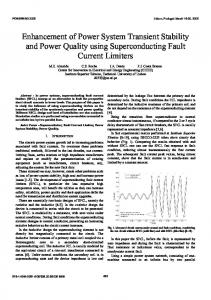
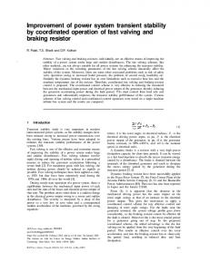
To assess the amount of Pc decrease necessary to stabilize an unstable scenario, a compensation scheme was proposed in [8,9].In this paragraph, a more pragmatic procedure is used; it consists of decreasing Pc by a preassigned factor3. The procedure is shortly illustrated on the four contingencies found to be harmful by FILTRA. Table 1 summarizes the obtained results. Column 2 provides the margin values; in their absence, the asterisk indicates that, instead, the “minimum distance” between the P,,,and P, curves is given 4.3 TransientStability Control (in MW). In column 4, Pci stands for initial power of the To stabilize a contingency found to be harmful by FULTRA, CMs, i.e., the power for which the stability margin of column SIME uses the corresponding critical machines and negative 2 was computed at the iteration of concern; in column 5, hpc stands for the suggested change of Pci. In column 6, Pcf margin provided at its output. stands for the final value of Pc; this is used as the initial Pc This stabilizationrelies on the knowledge of these two pieces value for the next iteration (provided that the critical group of information. It consists of acting on the power system does not change from one iteration to the other). generation to cancel out the margin. In turn. the equal-area criterion suggests that this may be achieved by adjusting the The stabilization procedure starts (iteration Nr 0) with the mechanical power of the OMIB or, equivalently, of the output data of the second block of FILTRA: margin qz, critical machines, Pc; further, in order to meet the load, the number of C M s , and corresponding Pc. To shorten power variation (generally decrease) on CMs must be explanations, we comment on the easy case of contingency compensated by an almost equal and opposite variation on Nr 10.Using the values provided by FILTRA,a first iteration is run using APc = -(27714-27714/1.03)=-808 MW. This non-critical machines. APc decrease is distributed among the 39 CMs, and an increase of the same amount is distributed among non-critical machines. A load flow is then run, followed by a transient stability simulation using SIME. The ,results are shown in the table: the procedure converges after one iteration; the power of the group of C M s guaranteeing stabilization is finally found to be of 27356 MW (in bold in the Table 1); in other ‘Ir words, stabilizing this case implies a decrease of 2.91% of CMS the generation power of the set of CMs. This process is represented graphically in Figure 5 . approach to contingency Filtering-Ranking and Assessment (FJLTRA) was proposed [5, 61. Figure 4 portrays its structure, describes its principle and illustrates it in the context of an investigation carried out on an EPRI test system [5,6,7].In short, the figure shows that, out of 36 screened contingencies, 25 are discarded straightway, while the remaining 11 are classified into 4 harmful, 3 potentially harmful and 4 harmless (the terminology is self-evident).
u Ranking u I Assessment block
Filtering block
Table 1: Stabilizing dangerous contingencies 1
1
Iter. Nr
1
2 Q
(rad./s)’
1
3 1 Nrof CMs
4
Pci
1
5 dpc
0 0
1
6
Pcf wulw)
1
7 1.
(m)
0 First Swing Stable contingency
Multi-Swing Harmless or Potentially Harmful contingency
Harmful contingency
Figure 4 A realizationof the “ I R A technique. Schematic description of the various contingency classes (Taken from [5,6]).
0-7803-6420-1/00/$10.00 (c) 2000 IEEE
Its value varies depending upon whether an initial margin exists or not. This latter case arises in very unstable situations where the post-fault configuration has no solution: the Pecurve does not intersect the P,,,curve.
1294
using the OPF program, reallocate the corresponding amount of active power on non-critical machines, so as to meet the predefined objective function (e.g. maximizing the power transfer on predefined tie lines), while respecting bus voltage and power line limits;
Figure 5 Stabilization process.
The same procedure yields the power limits for contingency Nr 1 in Table 1, as well. Observe that, generally, cases which involve changes of CMs during the procedure a n d or very unstable behavior (without initial margin) require a larger number of simulations; nevertheless, this number remains reasonably small (see contingency Nr 1 which accumulates the two “difficulties”).
5. INTEGRATED PACKAGE AND APPLICATIONS To perform ATC or CM calculations the previous section material is combined with an Optimal Power Flow program, as sketched in Figure 6.
(iv) the Transient Stability Assessment Block (block (3) in Figure 6) receives the “improved” operating point that was found by the OPF after applying the preventive control actions (in this case, generation rescheduling), and assesses transient stability of the power system with respect to the set of harmful contingencies. If the assessment block finds that the system is still unstable under some contingencies, it computes the corresponding margins, identifies the critical machines and sends this information back to the Transient Stability Control block (2). If the power system is stable for all contingencies, the new operating point is declared to be secure and the process stops.
The aim of this integrated scheme is to perform on-line calculations while meeting static and transient stability constraints. Figure 6 suggest that, in short, this combined “OPF + SIME approach proceeds as follows: (i)
System
Contingency Filtering Ranking and Assessment (FTLTRA)
using the output of the state estimator, the OPF computes the operating condition which meets a predefined objective function (e.g., maximum power transfer on predetermined tie-lines; minimum generation cost; etc), while respecting the static constraints of the transmission network elements (bus voltage and power line limits);
I
(ii) the FILTRA package (block (1) in Figure 6) identifies the set of unstable (harmful) contingencies from a very large initial set of probable contingencies. At the same time, it also computes stability margins and finds the set of critical machines corresponding to each one of the unstable contingencies; (iii) after receiving the information about critical machines and margins, the Transient Stability Control Block (block (2) in Figure 6) performs the following functions: 0
determine the corresponding control actions (active power change on each critical machine) for each one of the unstable (harmful) contingencies; combining the resulting control actions, compute the amount of active power change on each critical machine, necessary to stabilize all harmful contingencies simultaneously;
0-7803-6420-1/00/$10.00(c) 2000 IEEE
Reposed (New)
+
Stable Operatlng State
Figure 6 Integrated scheme for security constrained on-line ATC calculaticns (Adapted from [SI).
1295
Authorized licensed use limited to: Georgia Institute of Technology. Downloaded on April 15, 2009 at 11:02 from IEEE Xplore. Restrictions apply.
The cycle: “identification of the unstable contingencies and corresponding critical machines-computation of active power reallocation on each one of them-reallocation of the corresponding power among non-critical machines” is repeated until stabilizing all unstable contingencies. It is found that, generally, the process converges to the solution after two to three iterations. A final check is then performed to verify that the procedure has not destabilized any of the previously stable contingencies.
[5] Ruiz-Vega,D.; Emst, D; Machado Ferreira, C.; Pavella, M; Hirsch, P. and Sobajic, D. “A Contingency Filtering, Ranking and Assessment Technique for On-line Transient Stability Studies”. To be presented at the DRPT2OOO conference. London,UK; April 2000. [6] D E m s f D Ruiz-Vega. M Pavella, P Hirsch, and D Sobajic: “A Unified Approach to Transient Stability Contingency Wtering, Ranking and assessment”.Submitted to the IEEETrans. on Power Systems. [7] “Standard Test Cases for Dynamic Security Assessment”, Final EPRl report No. EPRl TR-105885. Electric Power Research Institute, Project 3103-02-03. December, 1995. [8] A.L. Bettiol, D. Ruiz-Vega, D. Emst, L. Wehenkel and M. Pavella: ‘Transient Stability-Constrained Optimal Power Flow”. Presented at IEEE Budapest Power Tech’99, Aug. 29 Sept. 2, 1999, Budapest, Hungary.
-
Discussion First note that block (2) stabilizes all contingencies simultaneously. Incidentally note that time-domain methods not only are inappropriate for providing fast contingency screening tools but. even more important, they are unable to design appropriate remedial actions for controlling (stabilizing) the unstable contingencies. This may explain why no transient stability assessment function has been implemented so far in control centers.
A final observation: the coupling of an OPF program with the TSA & control functions of SIME furnishes a real-time tool able to meet both, static and transient stability constraints. 6. CONCLUSIONS Today, it is necessary to optimize the utilization of the transmission network. Transmission utilization is public information readily available to the transmission users, regulators, and government agencies. With the coverage of dynamic security aspects for the real-time operation and day ahead energy transactions, transmission operators are able to operate the power system safely and reliably and at higher utilization levels. Control centers will implement dynamic security analysis functions [9].This paper describes an engineering solution to place into operation the missing TSA and control functions. REFERENCES
[I]
Pavella, M.: “Generalized OmMachhe Quivalents in Transient Stability Studies”, PES Letters, IEEE P o w Engineering Review. Vo1.18, No.1, January 1998. pp. 50-52. [2] Zhang, Y.;Wehenkel. L.; Rousseaux. P. and Pavella, M.: “SIME.A hybrid Approach to Fast Transient Stability Assessment and Contingency Selection”. Int. Joumal of Electrical Power and Energy Systems, Vo1.19. No.3, 1997,pp. 195-208. [3] Ruiz-Vega, D.; Bettiol. A. L;Emsf D.: Wehenkel L and Pavella M.: ‘Transient Stability-Constrained Generation Rescheduling”. Bulk Power System Dynamics and Control lV - Restructuring, Santorini. G-. August 1998. pp. 105-115. [4] Bettiol, A. L.; Wehenkel L and Pavella, M.: ‘Transient StabilityConstrained Maximum Allowable Transfer”, JEEE Transactim on Power Systems, Vol. 14, No. 2, May 1999. pp.654-659.
0-7803-6420-1/00/$10.00 (c) 2000 IEEE
[9] Giri Jay, Rene Avila Rosales: ‘‘Transient Stability Assessment: Integration with EMS and Control Center Requhements”. Presented at IEEE SingaporeWinter Meeting, Jan. 23 - 27,2000, Singapca.
Acknowledgements :The financial support of the Electric Power
Institute (project WW3103-10) for developing the filtering part of the +ILTRA scheme and for performing investigationson the EPRI system is gratefully acknowledged.
Research
BIOGRAPHIES Rene AvUa Resales is a Senior Power System Engineer at ALSTOM ESCA Corporation. He is with the Distribution Network Analysis group and focuses in static and dynamic transmission problems in the EMS. He is currently involved in the use of Object Oriented Technology for the development of three-phase applications in ALSTOM ESCA’s Distribution Management Platfom (DMP). Prior to joining ALSTOM ESCA he worked for the “Instituto de Invesrigaciones Elecrricm” (IIE) at Cuemavaca Morelos. Mexico supporting real-time advanced applications development and Dynamic Training Tools for “Comisirin Federal de Electricid” (CFE), the Mexican Utility.
Daniel Ruiz-Vega meived the Electrical Engineering degree from the Universidad Aut6noma Metropolitana (MQico) in 1991 and the M.Sc. degree from the Instituto Polibknico Naciod (M15xico) in 19%. He is presently a Ph.D. student at the University of Litge (Belgium). His rcsearch concems dynamic security assessment, with emphasis on real-time preventive transient stability control. Damien Ernst was bom in Verviers, Belgium in 1975. He is currently a Ph.D. student at the University of Liege (Belgium). and a FNFG Research Associate. His research concerns dynamic security assessment, with emphasis on real-time transient stability emergency control.
Mania Pavella received the Electrical (Electronics) Engineering degree and the PhD. degree both from the University of Iitge (Belgium), where she is presently a Professor. Her research interests lie in the field of electric power system analysis and control. She is an IEEE Fellow. Jay Giri is presently Manager, Power Systems Applications at ALSTOM ESCA Corporation and is a co-founder of the company. In his current role, Gin manages a team of power system application software developers who focus on real-time generation control, power system network analysis and training simulators. Prior to joining ALSTOM ESCA, Giri was a Power System Engineer at System Control in Palo Alto California. Giri is an affiliate Professor at the University of Washington and holds a Ph.D. in Electrical Engineering from Clarkson University in New York. He is coauthor of thc Energy Management System chapter in the Electrical Engineering handbook and is co-author of numerous technical papers and publications.
1296