On Methodology Using the ITU-T Languages and UML ROLV BRÆK
A methodology is a system of methods and principles, where each method defines a systematic way to produce given results. The general goal of a systems development methodology is to support development of systems of a high quality through a controlled process that is as efficient as possible. To this end a methodology seeks to prescribe what are good practices and what are not so good practices. Although they share the same overall goal, there are considerable differences among methodologies. A framework will be presented in the following that enables some principles to be identified and some important differences to be highlighted. One interesting question is how the ITU-T language family and UML stand in relation to each other from a methodology point of view. Rolv Bræk (56) received his Siv.ing. degree (M.S.E.E.) in 1969 from the Norwegian University of Science and Technology (NTNU) and is currently Professor in the Department of Telematics at NTNU. Rolv Bræk has extensive experience from application development using formal methods as well as from teaching, consulting and introducing systems engineering methodologies to industry. He is co-author of the book “Engineering Real Time Systems – An Object Oriented Methodology using SDL”, and “TIMe The Integrated Method” published on CD-ROM by SINTEF. His current research interest is rapid service development.
[email protected]
Why Methods? Nobody believes that knowing a natural language like English or Chinese is sufficient to write great novels. Nevertheless, some people believe that knowing a programming language like C or Java is all you need to write great software. Surprisingly many believe that knowing analysis and design languages such as the ITU-T languages or UML is sufficient to design great systems. By simply introducing UML, with supporting tools, they believe their development teams will design better systems at lower cost. This is of course not true! Like writing novels or making programs, system design takes a lot more than language knowledge. Part of this additional knowledge, when written down and presented systematically, is generally known as methods and methodology. Methods define a systematic way to produce given results, and therefore, constitute the core of a discipline like systems engineering. Without any methods there would be no discipline! In the context of systems engineering, methods prescribe how to go about producing specific results such as requirement specifications, design descriptions and test plans. Methodology is a system of methods and principles, put together to cover a larger part of the systems engineering process than a single method. The goal of systems engineering methodology is to help make better systems more efficiently and with better control. Ideally, knowing a methodology should be the same as knowing how to make great systems. In reality, good methodology helps people make sound solutions by bringing order into chaos and providing guidelines, but it does not replace human capabilities (creativity, experience, theoretical
knowledge, etc.). It is a kind of condensed and generalised experience presented in a systematic way. To understand the scope of systems engineering methods, it is necessary to step back and consider what it takes to develop successful products.
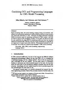
The Macro Cycle The bottom line is that successful systems satisfy real needs existing in some domain (market). The key to success is therefore first and foremost to understand the needs that are present in the domain (both those that are explicitly expressed and those implicitly present). The second issue is to analyse the needs and define (specify, design, implement) systems that can satisfy (some of) the needs in a cost-effective way. The last issue is to manufacture and install systems into the domain such that the needs are really satisfied and a maximal market share is created. This picture is not static. In the next run, the domain is changed by the installed systems, experience is gained and new needs arise that cause the cycle to repeat in a spiral-like way as illustrated in Figure 1. Figure 1 also illustrates that systems development deals with a reality consisting of domains and systems on the one hand and descriptions of the reality on the other. Traditional crafts use few descriptions1) if any, and most effort is focused on the reality itself. In systems engineering it is the opposite. It is an intellectual process where most effort is focused on descriptions, and comparatively little on the reality itself2). The main reason is that descriptions (e.g. mathemati-
1) The term “description” is used here in the general sense of a symbolic representation of something
as it is also used in the term “Formal Description Technique” (FDT). We do not distinguish between prescriptions, inscriptions and descriptions here. 2) One must of course always have the reality in mind and ensure that descriptions are valid.
96
Telektronikk 4.2000
Figure 1 The macro cycle/spiral DATAROM
Model
ADM EXIT
Domain descriptions
Domain
Install
Develop
System Manufacture
cal models, SDL diagrams, Java programs3)) are the only means by which the reality can be properly understood, communicated and analysed by human beings and by machines. Another reason is that, in many cases, one cannot afford to experiment and make mistakes with the real thing. Consequently, descriptions are the main objects of systems and software engineering. Having established the importance of descriptions, the next issue is to decide what descriptions to make and how to make them. These are the primary questions any systems engineering methodology should answer4). Most methodologies will agree with the macroscopic picture in Figure 1, that there are at least domain descriptions and system descriptions (although domain descriptions may not be emphasised by every methodology). Domain descriptions are developed in order to enable the people involved to understand an existing reality, assess needs and plan new systems. System descriptions, on the other hand, are used to create a new reality satisfying the needs. Although they are used for two different purposes (the domain descriptions to understand
System descriptions
and analyse; the system description to produce and document), they both describe a reality. In both areas we are looking for suitable ways to describe complex realities. The main difference between domain descriptions and system descriptions is that system descriptions are used constructively when manufacturing systems, and must describe technical solutions in more detail and more precisely than domain descriptions. In addition, they must be organised in a way that supports an efficient and controlled development process. Domain descriptions, in contrast, should not go into system specific detail, but rather provide a common conceptual frame of reference for product planning and system development. They should have a wider scope than system descriptions, in order to capture the needs and future usage context of systems in the domain. Once they are made, domain descriptions can be re-used in all systems developments targeting that domain, as long as the domain remains stable. It should be noted however, that many alternative domain descriptions may be developed for the same domain, and that the domain descriptions are likely to evolve as more insight and experience is gained even if the domain itself is not changing.
3) Note that programs are descriptions with the special property that a machine in the real world may
execute them. 4) But not every methodology has done that. Some have focused primarily on activities and treated
descriptions as secondary issues.
Telektronikk 4.2000
97
It is important to understand that the full macro cycle need not be performed for each system instance. Typically many system instances will be produced from the same system descriptions, and a given domain description may hold for several system descriptions. Each macro step produces results that can be maintained separately and can be the responsibility of different departments in a company, if so desired. Note that the descriptions (of domain and system) are the basis for communication between all the parties involved. Tradition has often caused different groups (e.g. marketing people and developers) to develop and use very different description techniques, which means that different groups communicate poorly and that the same information is repeated in different forms. An opportunity for improvement on the enterprise level is to introduce common languages and methods reducing the number of separate descriptions and increasing the value of each. The macro cycle in Figure 1 illustrates the golden principle of all methodologies, which is separation of concerns; in this case, to describe independent aspects in separate descriptions. A consequence of this principle is that each description focuses on aspects that are dependent.
How to Describe Complex Realities? In this section we do not distinguish between domain descriptions and system descriptions, but focus on the general problem of describing a complex reality5). We shall try to establish some basic principles and principal solutions before discussing language and method issues. First of all, it is important to realise that reality is so complex that a human being is unable to keep it all in mind at the same time. It is absolutely necessary to factor out aspects that can be understood one at a time and then be combined into an understanding of the whole. Two golden rules should be applied in combination: • Separation of concerns. Identify aspects that are as independent as possible and describe them separately. In this way, the complexity of each description is reduced, and may there-
fore be expressed more clearly. Separation also helps to increase the modularity of a set of descriptions by allowing descriptions concerned with independent aspects to be changed independently. Finally, if different aspects require different skills and knowledge, separation helps to utilise different kinds of expertise better. Note that separation is not a goal in itself. Little is gained if the separated parts are too dependent. • Conceptual abstraction. The general idea with abstraction is to remove irrelevant detail in order to focus on the essential. Conceptual abstraction means to replace low level concepts representing technical detail by more abstract concepts that are better suited to describe and study some aspects, i.e. by some kind of model. Mathematical models used for performance analysis and strength calculations are well known examples of conceptual abstraction. In order to be useful, a conceptual abstraction must capture the nature of the phenomena in a way that helps to improve understanding, communication and/or analysis. The essential purpose of ICT systems is to perform some logical behaviour6) and handle some information. This sets them apart from systems where physical strength, power or movement is part of the purpose. Physical devices like computers, cables, screens and cabinets are merely the means to realise ICT systems while their purpose is to provide some functionality. In order to focus on the essential, we need to separate the functionality7) in terms of logical behaviour and information handling from the accidental way it is implemented, and to model the functionality using a suitable conceptual abstraction. Three main aspects that are largely independent can be identified and separated in different descriptions8): • Functionality. This is a conceptual abstraction of logical behaviour and information. The purpose is to describe logical behaviour and information as clearly as possible. And to do so
5) In order to describe the “reality” we may apply generalisation into types as well as conceptual
abstractions. Descriptions may therefore be organised as description of general concepts (types, classes) and descriptions of particular phenomena (objects, instances). 6) We distinguish between logical behaviour and physical behaviour. Logical behaviour is the idealised behaviour that provides the system services. It is usually discrete, while physical behaviour involves physical properties and is usually continuous [14]. 7) Note that “functionality” is used here as a term to represent information handling and logical behaviour in a general sense. The mathematical term “function” has a more restricted meaning. 8) A further refinement is normally needed, but this serves to illustrate the main points.
98
Telektronikk 4.2000
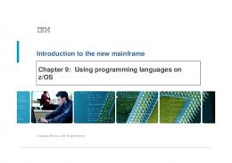
in terms that enable users and developers to communicate precisely, to establish a common understanding, and to ensure that the descriptions of functionality correctly represent the existing domain and/or the system being developed. It provides a view where the system may be seen as a whole, independent of realisation and technology. Functionality is normally described in terms of structures of active and passive objects with associated object behaviours. • Realisation. This is a precise technical definition of the realisation in terms of the different technologies used, such as mechanics, electronics and software. This view is necessary to actually produce a working system. A large number of realisations will normally be possible for a given functionality, and the choice will depend on what properties are desired from the realisation itself (often called nonfunctional properties). If properly separated, a given description of functionality may hold for several realisations. • Deployment. This defines a mapping between functionality and realisation by describing the realisation (the physical system) on a high level, by identifying the technologies used and by describing how and where the functionality is realised. It should focus on aspects that come in addition to the functionality, such as distribution, hardware/software allocation and use of middleware. Deployment and Functionality together may constitute the main design documentation. As indicated in Figure 2, the separations may be considered as different viewpoints of the same reality. The Reference Model for Open Distributed Processing (RM-ODP), identifies a different set of viewpoints: Enterprise, Information, Computational, Engineering and Technology, where the Computational and Information viewpoints cover Functionality [1], while the Engineering and Technology viewpoints (roughly) cover Deployment. Indeed, most contemporary methods for systems engineering identify these aspects, but the way that the aspects are represented in descriptions vary considerably, and so does the terminology used. Some will claim that it does not matter which method is used as long as some methods are used. This may well be true for methods based on similar conceptual abstractions, e.g. methods based on communicating state machines, but there are significant differences between conceptual abstractions and some of these differences have a strong impact on
Telektronikk 4.2000
methodology. The most important differences are found in the conceptual abstractions and languages used to express functionality.
How to Describe Functionality? It is desirable that the languages for functionality satisfy at least three essential requirements: • Human comprehension. Functionality should be represented in a way that enables human beings to fully understand it and to communicate precisely about it. To this end the concepts of the language must be well defined, and easy to understand. • Analytical possibilities. It should be possible to reason about behaviours in order to compare systems, to validate interfaces, and to verify properties. This requires a semantic foundation suitable for analysis. • Realism. The language should build on concepts that can be effectively realised in the real world. Although overlooked in many cases, this requirement is essential for two main reasons: 1. That it shall be possible to implement the functionality, 2. That the description of the functionality can serve as valid documentation of the real system. The choice of conceptual abstraction is the main key to all this. One reason why methods for communicating systems have developed differently from general software engineering methods is that they deal with different domains. In communicating systems, interactions between concurrently operating, physically distributed objects have been central, while data structures and algorithms have been more central in other areas. For this reason the conceptual abstractions developed for communicating systems have put concurrency and communication up front, and have treated data and algorithms in that context. This is clearly reflected in SDL where a system must be defined in terms of communicating state machines with a sequential behaviour that encapsulates data and algorithms. UML, in con-
Figure 2 Three main aspects or viewpoints
Descriptions Reality
Structure
Behaviour
Functionality (Structure + Behaviour)
Deployment
Realisation mechanics
electronics
software
99
trast, treats concurrency and State Machines as options, while Classes with Attributes and Operations are put up front. One may say that SDL puts the logical behaviour up front, while UML puts information up front. When different domains now are merged into modern ICT systems, there must be ways to combine the approaches. The well-known problems from the communication domain do not disappear. Logical behaviour involving concurrency and interactions will still be an important aspect to factor out, as it determines the way that services are provided to users and thereby how the users will judge the system quality. Logical behaviour is both complex and difficult to understand due to its dynamic (transient) nature. Therefore a conceptual abstraction of behaviour that facilitates understanding and communication about logical behaviour is extremely important. The drawback with programming languages in this area is that realism is achieved at the expense of human comprehension and analytical possibilities. Although programming languages (like CHILL, Java or C++) can describe logical behaviour, they do it by specifying action sequences. These are better suited to instruct the machine how to do things than to explain for the human being what is done. Humans need to understand the external interactions and the resulting evolution of state transitions that take place when the behaviour executes. Some of the more mathematical languages, like LOTOS and Z, emphasise analytical possibilities at the expense of realism (and to some extent human comprehension). This is one reason why they have not gained wider popularity. Communicating state machines of different forms are presently the best known conceptual abstractions used to describe logical behaviour, because they satisfy all three requirements above. State machines can be implemented in many ways, and combine realism with human
Figure 3 Objects and properties
Descriptions Properties
Objects
Service...
Performance... Dependability...
mechanics
100
electronics
software
Tests... Measurements
Functionality (Structure + Behaviour)
Deployment
Realisation
comprehension and analytical possibilities. For this reason state machines are part of most contemporary approaches, including UML and SDL. But in UML they are optional.
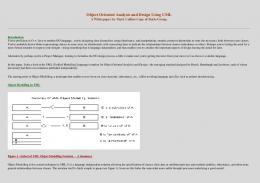
Object and Property Descriptions There is a general trend now to use object orientation as a common approach to describe both functionality, deployment and realisation. It is also a trend to use interaction scenarios to describe interactions between users and systems (use cases) and between objects within systems and among systems. Finally, state-transition based specifications are used to define the behaviour of individual objects. This is not very surprising, considering that more and more applications tend to be distributed and reactive. Object orientation helps to master complexity by providing a structure in terms of objects, and by factoring out common features in general classes or types. Objects do not live alone, but communicate with other objects. Describing the behaviour of each object in terms of states and transitions that are triggered by incoming signals from other objects has proven to be of great value, and is now adopted in one form or another in most system engineering approaches. A system generally consists of a structure of objects. Systems and objects are defined by means of object descriptions that represent how objects are related to other objects, how they are composed from attributes and other objects, and how they behave. Objects may be defined using Types or Classes, and inheritance may be used to define the Types/Classes. UML Class Diagrams, SDL diagrams and Java classes are all examples of object descriptions. Object descriptions provide the perspective of designers. Systems and objects generally have properties. Properties are defined by means of property descriptions that state external properties of a system or object without prescribing their internal construction. Property descriptions are not constructive, but are used to characterize an object from the outside. There are many kinds of properties: behaviour properties, performance properties, maintenance properties, etc. This is the perspective that is normally used in specifications. UML collaboration diagrams, MSC diagrams, test cases in TTCN, and performance figures are all examples of property descriptions. As illustrated in Figure 3, the separation between objects and properties is orthogonal to the three main viewpoints identified in Figure 2, leading to six different aspects to describe.
Telektronikk 4.2000
Properties associated with functionality are often called functional properties, while properties associated with deployment and realization are called non-functional properties.
ITU-T Objects UMLsdl.
Properties MSC
SDL, ASN.1,
The interplay between property descriptions and object descriptions is central to systems development. Normally the first step is to specify the required properties, then to use the properties as input to synthesize a design (defined by means of object descriptions); and finally to verify that the design satisfies the properties. In principle these three steps are performed for each viewpoint. An important advantage of the ITU-T languages MSC (for properties) and SDL (for objects) is that the relationships between properties and objects can be formally defined and supported by tools. It is important to note that a given property description may hold for many different object descriptions. A given set of MSC diagrams may, for instance be executed by several different SDL systems, and many alternative realizations may be able to pass the same set of TTCN test cases, and satisfy the same performance requirements.
Coverage by the ITU-T Language Family and UML Figure 4 shows how the ITU-T languages and UML cover the description aspects identified in Figure 3. Apparently, the coverage is similar, with deployment as one exception. Here UML offers component diagrams and deployment diagrams, while the ITU-T languages have no notation at all9) (but the issue is addressed in a new question for the study period 2001-2004: question Q11/10 Deployment and configuration language). The ITU-T languages must therefore be combined with other notations in this area, such as the one presented in [2] that was also used in the SDL method guidelines [3], or by UML. In the functionality area, the overlap is considerable after SDL-2000 has adopted (some of) the notation from UML Class Diagrams and the concept of composite states from UML State Machines. The need to use UML in combination with SDL has been greatly reduced by this, since the ITU-T languages now cover most aspects that were previously the strongpoint of UML. When comparing UML with SDL, we may note some important conceptual differences:
UML Objects
UseCase Diagrams, Sequence and Collaboration Diagrams, OCL, Activity Diagrams
Deployment and Component Diagrams, Class Diagrams
Sequence and Collaboration Diagrams, OCL
ODL TTCN, MSC
CHILL, ASN.1
Properties
Class Diagrams, State Maschines
TTCN, MSC
• In SDL, the concept of a system is central. A system has well defined interfaces and is composed from agents that operate concurrently and communicate by asynchronous message passing. A system models an executing part of the real world, but may be defined with reference to a system type. In UML there is no such system concept. There are only classes and associations between classes. Object structures may be described, but only for illustrative purposes.
Sequence and Collaboration Diagrams, OCL
Functionality
Deployment
Realisation
Figure 4 The ITU-T languages compared with the UML notations
• In SDL, an agent may be composed from a possibly complex structure of agents and can be defined as an agent type. In this way, a composite type can be defined and used as one entity with well-defined interfaces. UML lacks a corresponding concept of composite types. Composition is just a special association between classes in UML. • In SDL, concurrency and asynchronous communication between agents is the norm. State machines define the sequential behaviour of agents. In UML, concurrency and asynchronous communication is an option. Some of these differences may disappear in UML 2.0, but presently UML is not really a system modelling language. It is an open ended and flexible language for modelling classes without internal structure (apart from attributes). This makes it well suited for visual modelling of object oriented software, but not really for system modelling – as yet. For system modelling SDL provides more powerful conceptual abstractions, and in addition an action semantics that makes
9) One could argue that the ITU-T Object Definition Language (ODL) belongs to deployment, but the
main focus of the language is objects and interfaces providing functionality. One may also argue that it is a property language, as the main focus is on interface definitions.
Telektronikk 4.2000
101
its behaviour well defined. A methodology using UML may compensate for this to some extent by providing guidelines and rules and more precise interpretation of UML. MSC and UML Sequence Diagrams are basically the same, but UML Sequence Diagrams lack the decomposition/composition mechanisms that MSC provides, and this gives MSC clear advantages when dealing with more complex cases. UML Collaboration Diagrams offer a view on interactions that many find useful, but this view is missing in the ITU-T language family. TTCN and ASN.1 cover aspects that UML is missing entirely.
Figure 5 The elaboration approach vs. the translation approach
Note that Class Diagrams are mentioned also in the Deployment compartment for UML. One reason for this is that UML classes may be useful to visualise high-level realisation classes. A more important reason is that many people actually use UML Class Diagrams on a very low level just to visualise realisation classes, such as Java classes. Considerable method support is required to use UML with sufficient conceptual abstraction to be useful as Functionality description. Many UML users are not aware of this, but keep the UML use as a kind of visual programming. This is especially true for people with a strong programming background and little modelling experience.
Elaboration approach
Functionality
Deployment
Realisation
Translation approach
Functionality
Deployment
Realisation
Initial development
New service Effort spent
102
New realisation
Elaboration vs. Translation We may distinguish between two fundamentally different approaches to systems development: • The elaboration approach. Here the functionality is described using informal languages with incomplete semantics, and therefore the functionality description is incomplete. Details have to be added by elaboration during deployment design and realisation. As a result, the realisation description ends up as the only complete view of the system and is often the only one that is maintained. This gradually reduces the value of the other views, and makes the documentation very realisation dependent. When the technology and platforms change, as they do fast these days, more than necessary must be redone, because it is hard to factor out and reuse functionality that is not changed. Mainstream software engineering has followed the elaboration approach, and this has also been the case for most UML use including the Rational Unified process, RUP. • The translation approach. Here the functionality is described as completely as possible using a language with well-defined and realistic semantics. The deployment is kept as orthogonal as possible to the functionality (using the principle of distribution transparency), and realisation of functionality is carried out by (manual or automatic) transformation of the functionality description. Advantages of this approach are that the functionality can be completely defined, analysed and simulated before implementation, and that the functionality description can remain valid for the realisation and serve as documentation. It may even be possible to generate the (application part of) realisations automatically, but this depends on the language and available tools. Functionality descriptions can apply to several implementations and survive technology and platform changes, and thereby give better return of investment, which is desirable, since functionality tends to last longer than realisations. The impact that this choice of approach has on methodology and on the potential for process improvement should be obvious. But it has been a popular opinion that the translation approach is infeasible in a real industrial setting, and therefore the take-up of the translation approach has been slow. This may be partially caused by reluctance to introduce formal methods, especially among programmers. However, the translation approach does work, and many companies are now using it routinely in their product developments with good results. Experience from using the translation approach with SDL has shown that the approach helps to reduce the
Telektronikk 4.2000
number of errors in systems considerably10), even when the translation to implementation is done manually. With automatic code generation, the figures are even better, because the translation errors are removed; see the article by Richard Sanders on implementing from SDL in this issue. Separating the description of functionality from the realisation gives some additional benefits. First, that it provides a view where the system may be seen as a whole, independent of realisation technology. Second, that it can remain stable and survive technology changes. Finally, that it provides a solid foundation for technology trade-off and optimisation. Figure 5 is an illustration of the differences between the two approaches. In the translation approach the viewpoints/aspects are well separated, while in the elaboration approach the separations are not so clear. Comparatively more effort is spent on functionality in the translation approach and less effort on realisation. Since functionality is expressed using formal languages, the quality of functionality can be assured separately from the quality of realisation. Provided that the realisation of functionality is automatically generated, the testing may concentrate on non-functional properties like performance and response times. An important point illustrated in the figure, is that the functionality description need not be changed if the realisation platform or programming language is changed. When using the translation approach, it is sufficient to change the deployment and realisation. The functionality description can be reused and thereby provide a better return of investment than possible when using the elaboration approach. One Norwegian company for instance, migrated from CHILL to C++ by changing their code generator and generate the new C++ code from the same SDL source as they previously used to generate CHILL.
Quality Assurance Quality assurance techniques come in two main categories: • Corrective techniques that focus primarily on defect detection, with subsequent correction. All the traditional verification and validation techniques including simulation, testing and inspection are in this category. • Constructive techniques that focus primarily on defect avoidance, i.e. to avoid introducing errors in the first place. Tools for design synthesis and automatic program generation are
obvious examples, but languages and methods that help to improve understanding and communication are clearly in this category too. Corrective techniques may be seen as iterative, while constructive techniques are formative. The quality of ICT systems can be split into two main aspects as suggested by Figure 2: • Quality of functionality, that is related to the main purposes, i.e. the needs of the domain, and is concerned with the information handling and logical behaviour. • Quality of realisation, that is related to the way the functionality is realised. These aspects are quite independent and should as much as practically possible be separated (according to the golden rule on separation of concerns). With the elaboration approach, a clear separation of concerns is more difficult than in the translation approach. The ITU-T languages offer many advantages here, due to their conceptual abstractions, their well-defined semantics, and the possibility to define formal relationships between descriptions. An SDL model can for instance be extensively simulated and validated before implementation takes place, and implementation errors can be avoided by automated translation to realisation code. SDL models may be formally verified against properties specified in MSCs, and TTCN test cases can be derived from MSCs and thereby ensure that the realisation is conformant with the specification.
Method Maturity Level Some companies using the translation approach have made the transition from implementation oriented development to design oriented development. They no longer treat the implementation code, in e.g. C++, as their primary documentation, but as secondary, derived documentation. Application designs expressed in languages such as SDL and MSC have taken over the role as primary documentation. On this level the application is understood and maintained in terms that are closer to user understanding. However, there is a snag: the amount of detail required to enable automatic code generation may clutter the description and reduce readability to a level where human errors are likely to increase. Some sort of layering is required to avoid this. Steve Randall describes one approach in his paper in this issue. Another approach is used in TIMe [4] where the functionality is split into an application part and an infrastructure part that are combined in a framework.
10) At least by 50 %.
Telektronikk 4.2000
103
Domain
Install System
System
Figure 6 Macro methodology12)
Domain description
Model Domain
Develop System
Produce System
System description
Those that have moved to design oriented development, naturally seek further improvements. In a competitive market place, the ability to add new services (or modify existing services) with short time to market, while keeping the quality stable at a high level, is often sought as the next improvement. In practice, this means to focus more on the domain and the properties. Issues that emerge then are how to model properties separately and how to compose and map properties to designs. The ideal situation would be property oriented development, where designs are derived automatically from property descriptions. Although this vision cannot be realised today, some small steps in that direction have been made using existing languages and tools. Using MSC to describe behaviour properties, for instance, offers some possibilities. First, because MSCs provide a readable and precise way to describe interaction behaviour and thus help to avoid errors, and secondly because MSCs can be used both constructively to (partially) synthesise application designs, and correctively to verify that application designs satisfy the properties specified in an MSC.
Methodology The macro cycle/spiral in Figure 1 suggests a macro methodology as represented in Figure 6. Although it is very simplified, almost naïve, it illustrates the scope of methods and methodology: a set of results and activities. Note that all the activities in Figure 6 may go on at the same time, and normally will do so, by working on different individual results. Four main result areas with associated activities are identified in Figure 6, and a set of methods (a sub-methodology) can be defined for each of them11). A central issue of methodology is to specify the results:
• What results should be achieved? At least descriptions covering the six different aspects we have identified in Figure 3 should be developed. The description icons in Figure 6 illustrate this. • What should the results be like? The language/notation to use in each description must be specified, and rules must be provided for language use, both concerning the appearance (syntax) and the meaning (semantics). • What relationships should hold between results? What are the rules for consistency between descriptions that can be used for verification and validation? What rules ensure a consistent documentation? In principle, the activities are just means to achieve the results. In practice, they need to be broken down and explained both to provide guidelines and to facilitate project control. But the decomposition should focus primarily on steps in the result space, and not on activities per se. For each activity a method may specify: • • • • •
Guidelines for performing the activity; Preconditions for starting the activity; Intermediate results that should be produced; The final results (outputs) of the activity; The sub-activities that should be performed.
We may illustrate this by the system development activity. The goal here is to develop the six aspects of system descriptions such that the complete result satisfies all the rules and the relationships. This is achieved by decomposing the “Develop system” activity in Figure 6. A natural progression through intermediate results using the translation approach is illustrated in Figure 7. Here we have illustrated the state of the system description by colouring the fields of the icon that represent a description aspect that is ready. This shows a normal progression of description states. The figure may seem to describe a pure “waterfall” approach where each description aspect must be completed before starting on the next, but this is not necessarily the case. Each description aspect may consist of parts that may be developed separately, either in parallel or in sequence. By allowing activities to start with partial input and to run in parallel, the methodology can support alternative ways to order the activities over time, such as an incremental process or a spiral process.
11) Note that methods and methodology are concerned with how to produce the best possible results,
not actually producing them. 12) Note that the domain and the system are represented by separate descriptions that each may
cover all six aspects.
104
Telektronikk 4.2000
Sometimes, such figures as Figure 7 are mixed up with descriptions of development processes. A development process is a generalised project plan that specifies an ordering of milestones/ results and activity executions that every project should follow. Contrary to a methodology, a process specifies the activity executions in phases that actually produce results. A methodology should be more general and describe rules and guidelines in a way that can be applied by several processes. Therefore, a methodology should focus on activity types rather than activity instances (executions of activities). It should be possible to enact the activities in many ways and still produce results according to the guidelines and rules of the methodology. Languages, or description techniques, determine the way that the reality can be described and understood. It is not so much the syntax of the languages that matters as the underlying concepts, or meaning. It is conceptual differences that really make methods and methodologies different. Many guidelines and rules focus on the meaning of descriptions rather than the syntax they are expressed with. Such guidelines and rules may often be applied to a range of languages using different syntax as long as the underlying concepts are similar. Summing up, the core of systems engineering methodology is a set of descriptions, rules for well-formed descriptions, defined relationships between descriptions and guidelines for activities.
Some Methods The first methods using the ITU-T language SDL were developed more than 20 years ago. Several industrial product developments at that time demonstrated that the quality of complex real time systems could be managed by means of the conceptual abstraction that the language provided, combined with a translation approach. At that time hardly any tools existed, so the products were developed using hand drawings in SDL and manual code generation. The author was responsible for one early method, called SOM that was used on an industrial scale by several companies during the late 1970s – early 1980s. Experiences from its first five years of use can be found in [5]. Based on positive experiences with SOM and similar methodologies, several Norwegian companies joined forces in the SISU project aiming to further develop and disseminate such method-
Specify functionality
Design functionality
Specify deployment
Design deployment
Specify realisation and test
Realise and test
ologies. It was realised that the best way to ensure wide acceptance and adequate tools would be to use internationally standardised languages and work to make these as good as possible. SISU therefore funded parts of the Norwegian contributions towards the MSC-92 language and to make SDL-92 object oriented. This effort on standardisation was complemented with development of a methodology using SDL-92 and MSC-92 in combination with a notation called SOON13) for general object modelling. The method was documented in [2]. This methodology was further developed into TIMe, The Integrated Method [4], [6], based on SDL-96 and MSC-96 combined with UML.
Figure 7 Sub-activities and intermediate descriptions of “Develop system”
During the same period, many companies developed methods using the ITU-T languages for their own internal use, see e.g. [7], and the tool vendors Telelogic and Verilog defined methods to help their customers use the languages and tools to their advantage [8], [9]. Method guidelines were also defined by the ITU-T [3], [10], [11], and ETSI developed method guidelines as explained in the paper by Steve Randall in this issue. Lately the Rational Unified Process, RUP [12], [13], has been receiving considerable attention. It should be noted that RUP is not a methodology, but a web-enabled software engineering process using UML and Rational tools, such as Rational Rose. RUP is based on the elaboration approach.
13) SOON was used for the same purposes as UML are used for when combined with SDL: general
conceptual descriptions and deployment descriptions. The main reason for using SOON was that there were no UML available at that time.
Telektronikk 4.2000
105
References 1
2
Ek, A. The SOMT Method. Malmö, Telelogic, 1995. (http://www.telelogic.com/ download/papers/SOMT.pdf)
9
ObjectGEODE – Method Guidelines. Toulouse, Verilog, 1997.
Bræk, R, Haugen, Ø. Engineering Real Time Systems. An object-oriented methodology using SDL. Prentice Hall, 1993. (ISBN 0-13034448-6.)
10 Reed, R. Methodology for Real Time Systems. Computer Networks and ISDN Systems, 28, 1996.
3
ITU-T. SDL methodology Guidelines. Geneva, 1992. (ITU-T Recommendation Z.100, annex I.)
4
TIMe: The Integrated Method; Electronic textbook. 2000, November 15 [online] – URL: http://www.informatics.sintef.no/ projects/time/
5
106
8
ITU-T. Basic Reference Model of Open Distributed Processing – Part 1: Overview. Geneva, 1997. (ITU-T Recommendation X.901.)
Bræk, R, Helle, O, Sandvik, F. SOM : An SDL Compatible Specification and Design Methodology. Experiences from 5 years of extensive use. 4th International Conference on Software Engineering for Telecommunication Switching Systems (SETSS), 1981. (IEE conference publication no. 198.)
6
Bræk, R et al. Quality by Construction Exemplified by TIMe – The Integrated Method. Telektronikk, 95 (1), 73–82, 1999.
7
Robnik, A, Dolenc, M, Alcin, M. Industrial Experience Using SDL in IskraTEL. In: Proceeedings of Seventh SDL Forum. SDL’95. Bræk, R, Sarma, A (eds.). Elsevier, 1995. (ISBN 0 444 82269 0.)
11 ITU-T. SDL+ Methodology: use of MSC and SDL [with ASN.1], Supplement 1 (05/97). Geneva, 1997. (ITU-T Recommendation Z.100.) 12 Kruchten, P. Rational Unified Process – An Introduction. Addison-Wesley, 2000. (ISBN 0-201-70710-1.) 13 Rational Unified Process. 2000, November 15 [online] – URL: http://www.rational.com/ products/rup/index.jsp 14 Shakeri, A. A Methodology for Development of Mechatronic Systems. Trondheim, Norwegian University of Science and Technology, Department of Telematics, 1998. (PhD thesis 1998:104.)
Telektronikk 4.2000