Danny Dolevââ and Ezra N. Hoch .... 1. pulsedp(r) = T rue, in case 0 ⤠r â k (mod Ï + Ï) < Ï; and ..... tems (OPODIS'03), La Martinique, France, Dec 2003.
On Self-stabilizing Synchronous Actions Despite Byzantine Attacks? Danny Dolev?? and Ezra N. Hoch School of Engineering and Computer Science, The Hebrew University of Jerusalem, Israel, {dolev,ezraho}@cs.huji.ac.il
Abstract. Consider a distributed network of n nodes that is connected to a global source of “beats”. All nodes receive the “beats” simultaneously, and operate in lock-step. A scheme that produces a “pulse” every Cycle beats is shown. That is, the nodes agree on “special beats”, which are spaced Cycle beats apart. Given such a scheme, a clock synchronization algorithm is built. The “pulsing” scheme is self-stabilized despite any transient faults and the continuous presence of up to f < n3 Byzantine nodes. Therefore, the clock synchronization built on top of the “pulse” is highly fault tolerant. In addition, a highly fault tolerant general stabilizer algorithm is constructed on top of the “pulse” mechanism. Previous clock synchronization solutions, operating in the exact same model as this one, either support f < n4 and converge in linear time, or support f < n3 and have exponential convergence time that also depends on the value of max-clock (the clock wrap around value). The proposed scheme combines the best of both worlds: it converges in linear time that is independent of max-clock and is tolerant to up to f < n3 Byzantine nodes. Moreover, considering problems in a self-stabilizing, Byzantine tolerant environment that require nodes to know the global state (clock synchronization, token circulation, agreement, etc.), the work presented here is the first protocol to operate in a network that is not fully connected.
1
Introduction
Most distributed tasks require some sort of synchronization. Clock synchronization is a very basic and intuitive tool for supplying this. pulse synchronization can be used as an underlying building block to achieve clock synchronization, as well as solving other synchronization problems; in a sense, pulse synchronization is a more fundamental synchronization problem. It thus makes sense to require an underlying pulse synchronization mechanism to be highly fault-tolerant. This paper presents a pulse synchronization algorithm that is self-stabilizing and is tolerant to permanent presence of ? ??
A pre-copy of the paper appearing in Disc, Sept. 2007. Part of the work was done while the author visited Cornell university. The work was funded in part by ISF, ISOC, NSF, CCR, and AFOSR.
2
Danny Dolev and Ezra N. Hoch
Byzantine faults. That is, it attains synchronization, once lost, while containing the influence of the permanent presence of faulty nodes. Consider a system in which the nodes execute in lock-step by regularly receiving a common “pulse” or “tick” or “beat”. The objective is to agree on some “special beats” that are Cycle beats apart. We will use the “beat” notation for the “global” signal received, and “pulse” for the “special beats” agreed upon. The pulse synchronization problem is to ensure that eventually all correct nodes pulse together, and as long as enough nodes remain correct, they continue to pulse together, Cycle beats apart. For example, given Cycle = 7 we would like all correct nodes, that may start at arbitrary initial states, to eventually pulse together every 7 beats, and continue so as long as there are enough correct nodes. The global beat system provides some measure of synchronization. For example, given a global beat system with beat interval at least as long as the worst-case execution-time for terminating Byzantine agreement, the pulse synchronization problem is solved by initiating a Byzantine agreement on the next time when the nodes should pulse, each time a beat is received. The crux of the problem is to achieve synchronization when it is not given by the global beat system; that is, when the beat interval length is in the order of the communication’s end-to-end delay. Since in that scenario the global beat system does not provide - by itself - enough synchronization, and a more complex algorithm is required to exert the required synchronization. The main contribution of the current paper is achieving exactly that. Related Work: pulseing has been used as an underlying fault tolerant mechanism in clock synchronization, token circulation and to create a general stabilizer (see [4] for an overview). All of these algorithms are self-stabilizing and Byzantine tolerant, due to the fault tolerant nature of the underlying pulse mechanism. This gives the motivation for producing robust and efficient pulseing algorithms, as they can be used to improve the robustness of a variety of applications. Clock synchronization is one of the first problems that was solved in a selfstabilizing and Byzantine tolerant fashion. In [9] and [12] it was solved directly, and in [4] it was solved using an underlying pulseing algorithm. [9] was the first work to discuss the exact same model as presented here, as opposed to [4], which operates without a global beat system. Synchronization of clocks of integer values was previously termed digital clock synchronization ([2,7,8,16]) or “synchronization of phase-clocks” ([11]). However, in this paper we concentrate on the pulseing mechanism, as it yields clock synchronization as well as other fault tolerant protocols. Several fault tolerant stabilizers exist (see [1], [10] and [13]) with varying requirement and features (such as local containment of faults). In [3], it was shown that pulse synchronization can be used to create a generalized stabilizer. However, in [3] the stabilizer is complex, and can stabilize a narrow class of algorithms. In Section 9 we show a simpler stabilizer, which can stabilize a wider range of algorithms.
On Self-stabilizing Synchronous Actions Despite Byzantine Attacks
3
Some of the previous results combining Byzantine faults and self-stabilization consider a class of problems in which the state of each correct node is determined locally. Usually such solutions can operate in a general graph (see [17], [15] and [14]) without the need to aggregate or accumulate information across the network. In the class of problems in which the state of each correct node is correlated with the state of the other correct nodes, the current paper is the first paper to present a solution that operates in a network that is not fully connected. Contributions: We construct a self stabilizing pulseing algorithm, that is tolerant to up to f < n3 Byzantine nodes, and converges in linear time, for any target interval of pulsing. As will be shown in Section 8, clock synchronization and pulse synchronization are equivalent. Hence, this work is compared to the state of the art of previous clock synchronization results that operate in the exact same model. Previous results have either linear convergence time with f < n4 (see [12]) or exponential convergence time with f < n3 (see [9]). In this paper we obtain a linear convergence time with f < n3 . Moreover, our convergence time is independent of the max-clock value (the clock wrap around value) of the digital clock, in contrast to [9]. In addition, our algorithm is the first one in this model and for this type of problems that does not require each node to be connected to every other node, it only requires that there are 2 · f + 1 distinct routes between any two correct nodes, matching the lower bound of [5].
2
Model and Definitions
Consider a fully connected network of n nodes (we later generalize the results to a more general network). All the nodes are assumed to have access to a “global beat system” that provides “beats” with regular intervals. The communication network and all the nodes may be subject to severe transient failures, which might leave the system in an arbitrary state. We say that a node is Byzantine if it does not follow the instructed algorithm and non-Byzantine otherwise. Thus, any node whose failure does not allow it to exactly follow the algorithm as instructed is considered Byzantine, even if it does not behave fully maliciously. A non-Byzantine node will be called nonfaulty. In the following discussion f will denote the upper bound on the number of Byzantine nodes.1 The presented solution supports f < n3 . Definition 1. The system is coherent if there are at most f Byzantine nodes, and each message sent at a beat to a non-faulty destination arrives and is processed at its destination before the next beat. Nodes are instructed to send their messages immediately after the occurrence of a beat from the global beat system. Therefore, when the system is coherent 1
In the literature the term ”permanent” Byzantine node is sometimes used.
4
Danny Dolev and Ezra N. Hoch
message delivery and the processing involved can be completed between two consecutive global beats, by any node that is non-faulty. More specifically, the time required for message delivery and message processing is called a round, and we assume that the time interval between global beats is greater than and in the order of such a round. Due to transient faults, different nodes might not agree on the current beat/round number. We will use the notion of an external beat number r, which the nodes are not aware of, but will simplify the proofs’ presentation and discussion. At times of transient failures there can be any number of concurrent Byzantine faulty nodes; the turnover rate between faulty and non-faulty behavior of nodes can be arbitrarily large and the communication network may also behave arbitrarily. Eventually the system behaves coherently again. At such case a nonfaulty node may still find itself in an arbitrary state. Since a non-faulty node may find itself in an arbitrary state, there should be some time of continues non-faulty operation before it can be considered correct. Definition 2. A non-faulty node is considered correct only if it remains nonfaulty for ∆node rounds during which the system is coherent.2 The algorithm parameters n, f, as well as the node’s id are fixed constants and thus are considered part of the incorruptible correct code at the node. Thus, it is assumed that non-faulty nodes do not hold arbitrary values of these constants. 2.1
The pulseing Problem
We say that a system is [φ, ψ]-pulsing if all correct nodes pulse together in the following pattern: φ consecutive beats of pulses followed by ψ consecutive beats of non-pulse. That is, the system has a Cycle of length φ+ψ beats, out of which only the first φ beats are pulses. More formally, denote by pulsedp (r) = T rue if p pulsed on beat r and pulsedp (r) = F alse, otherwise. Definition 3. A system is [φ, ψ]-pulsing in the beat interval [r1 , r2 ] if there exists some 0 ≤ k < φ + ψ, such that for every correct node p, and for every beat r ∈ [r1 , r2 ], it holds that: 1. pulsedp (r) = T rue, in case 0 ≤ r − k (mod φ + ψ) < φ; and 2. pulsedp (r) = F alse in case φ ≤ r − k (mod φ + ψ) < φ + ψ. (k denotes the offset, from r1 , of the first pulse in the pattern.) For example, consider “1” to represent a beat in which all correct nodes pulse, and “0” a beat in which all correct nodes do not pulse. Using this notation, the following is a pulseing pattern of a [φ, ψ]-pulsing system. φ beats ψ beats φ beats ψ beats z }| { z }| { z }| { z }| { [. . . , 1, 1, . . . , 1, 0, 0, . . . , 0, 1, 1, . . . , 1, 0, 0, . . . , 0, . . .] | {z } | {z } Cycle beats Cycle beats 2
The assumed bound on the value of ∆node is defined in Remark 3.
On Self-stabilizing Synchronous Actions Despite Byzantine Attacks
5
Definition 4. The pulseing problem: Convergence: Starting from an arbitrary state, the system becomes [φ, ψ]-pulsing after a finite number of beats. Closure: If the system is [φ, ψ]-pulsing in the beat interval [r1 , r2 ] it is also [φ, ψ]-pulsing in the interval [r1 , r2 + 1]. Definition 5. a [φ, ψ]-pulser is an algorithm A, such that once the system is coherent (and stays so), it solves the pulseing problem. The objective is to develop an algorithm that pulses only once every Cycle. Notation: We denote a [1, ψ]-pulser as [ψ + 1]-pulser. Using the previously used notation of “1” for pulseing and “0” for nonpulseing, a [Cycle]-pulser looks as follows: [. . . , 1, 0, 0, . . . , 0 , 1, 0, 0, . . . , 0 , . . .] {z } | {z } | Cycle beats Cycle beats The goal is to build a [Cycle]-pulser for any Cycle > 0. That is, a selfstabilizing, Byzantine tolerant algorithm that eventually pulses every Cycle beats. The following section outlines the solution.
3
Constructing a [Cycle]-pulser
In contrast to previous solutions that were very involved, the new solution presented below is more modular. Addressing the problem in a modular way enabled us to unwrap the difficulties in solving the problem, and to come up with a tight solution. Its modularity also enables to simplify the proof of correctness and to better present the intuition behind it. The core of the protocol is the Large-Cycle-Pulser algorithm that produces a [∆, ∆ + Cycle0 ]-pulser. This module uses another module called BBB to limit the ability of the Byzantine nodes to disrupt the protocol. To obtain the complete solution the core protocol is wrapped with two additional modules, as detailed below. We first show how to construct a [∆, ∆ + Cycle0 ]-pulser A for any Cycle0 > ∆, where ∆ is a bound on running a given distributed agreement protocol. We continue by showing how to construct a [φ + ψ]-pulser from any [φ, ψ]-pulser. Using this, we construct a [2 · ∆ + Cycle0 ]-pulser A0 for any Cycle0 > ∆. Lastly, using A0 , we construct a [Cycle]-pulser for any Cycle ≥ 1. Remark 1. Note that [φ + ψ]-pulser is actually [1, φ + ψ − 1]-pulser, and hence a [φ, ψ]-pulser (pulses for φ beats then it is quiet for ψ beats) is transformed into a [1, φ + ψ − 1]-pulser (pulses once, then it is quiet for φ + ψ − 1 beats). The construction of A uses a building block that is essentially a Byzantine consensus. We denote this building block by BBB (Byzantine Black Box).
6
Danny Dolev and Ezra N. Hoch
3.1
The Byzantine Black Box Construction
BBB is defined to be a round based distributed protocol, such that each node p has a binary input value vp and a binary output value Vp . BBB has the following properties: 1. Termination: The algorithm terminates within ∆ rounds. 2. Agreement: All non-faulty3 nodes agree on the same output value V. That is, for any two non-faulty nodes p, p0 it holds that Vp = Vp0 = V. 3. Validity: If n − f non-faulty nodes have the same input value ν then that is the output value, V = ν. BBB is required to be Byzantine tolerant, but is not required to be selfstabilizing. The self-stabilization of the [φ + ψ]-pulser A (presented later) will not be hampered by this.4 In addition, A will rely only on the properties of BBB (when it is executed by enough correct nodes) for its operation. In A all messages exchanged among the nodes will use BBB. Since the presented BBB can tolerate f < n3 faulty nodes, A can tolerate the same failure ratio. Remark 2. BBB can be implemented via any algorithm that solves the Byzantine consensus problem; the only difference lies in the “validity” condition, where instead of limiting the validity to the case that “all correct nodes” start with the same initial value, BBB limits the validity condition to having only n − f non-faulty nodes with the same initial value, even if there happen to be more non-faulty nodes at that instance. Remark 3. A non-faulty node that has recently recovered from a transient failure cannot immediately be considered correct. In the context of this paper, a nonfaulty node is considered correct once it remains non-faulty for at least ∆node = ∆ + 1, and as long as it continues to be non-faulty. 3.2
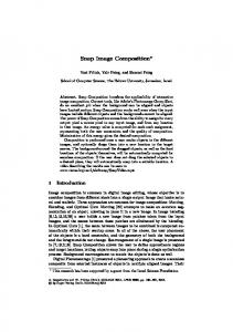
A [∆, ∆ + Cycle0 ]-pulser
Figure 1 presents an algorithm that produces a [∆, ∆ + Cycle0 ]-pulser, for Cycle0 > ∆. This algorithm executes ∆ simultaneous BBB protocols. Consider BBB i as a “pointer” to a BBB instance, hence the statement BBB 2 := BBB 1 ; BBB 1 := new BBB(“1”); means that BBB 2 will contain the previous instance of BBB 1 , and BBB 1 will contain a new instance of BBB initialized with the input value 1. The output value of BBB i is V(BBB i ). 3
4
in the context of BBB, a node is considered non-faulty only if it is non-faulty throughout the whole execution of BBB. BBB is initiated, executed and terminated repeatedly; each instance starts with a “clean slate”, thus not harming the self-stability of the algorithm that uses it.
On Self-stabilizing Synchronous Actions Despite Byzantine Attacks Algorithm Large-Cycle-Pulser
7
/* executed repeatedly at each beat */
1. for each i ∈ {1, .., ∆} do execute the ith round of the BBBi protocol; 2. (a) if Counter > 0 then Counter := min{Counter − 1, Cycle0 }; W antT oP ulse := 0; (b) else W antT oP ulse := 1; 3. if V(BBB∆ ) = 1 then (a) do pulse; (b) Counter := Cycle0 ; 4. for each i ∈ {2, ..., ∆} do BBBi := BBBi−1 ; 5. initialize a new instance of BBB, BBB1 = BBB(W antT oP ulse).
Fig. 1. A [∆, ∆ + Cycle0 ]-pulser algorithm for Cycle0 > ∆.
4
Proof of Large-Cycle-Pulser’s correctness
All the lemmata, theorems, corollaries and definitions hold only as long as the system is coherent. We assume that nodes may start in an arbitrary state, and nodes may fail and recover, but from some time on, at any round there are at least n − f correct nodes. Let G denote a group of non-Byzantine nodes that behave according to the algorithm, and that are not subject to (for some pre-specified number of rounds) any new transient failures. We will prove that if |G| ≥ n − f and all of these nodes remain non-faulty for a long enough period of time (Ω(∆) global beats), then the system will converge. For simplifying the notations, the proofs refer to some “external” beat number. The nodes do not maintain it and have no access to it; it is only used for the proofs’ clarity. Definition 6. A group G is Correct(α, β) if |G| ≥ n−f , and every node p ∈ G is correct during the beat interval [α, β]. Let δ mark the length of the interval, that is δ = β − α + 1. Note that each node p ∈ G, when G is Correct(α, β), has not been subject to a transient failure in the beat interval [α − ∆node , β]; and is non-faulty during that interval. Definition 7. We say that a system is Correct(α, β) if there exists a set G such that G is Correct(α, β). In the following lemmata, G refers to any set implied by Correct(α, β), without stating so specifically. The proofs hold for any such set G. Note that if the system is coherent, and there has not been a transient failure for at least ∆ + 1 beats, then, by definition, G contains all nodes that were nonfaulty during that period.
8
Danny Dolev and Ezra N. Hoch
Lemma 1. ∀β ≥ α: If the system is Correct(α, β) then at any beat r ∈ [α, β], either all nodes in G pulse or they all do not pulse. Proof. A node pulses only in Line 3.a, which is executed only when the value of V(BBB ∆ ) = 1. All nodes in G have not been subject to transient failures in the ∆node = ∆ + 1 beats preceding r. Therefore, BBB ∆ has been initialized properly ∆ beats ago, and during the ∆ rounds of BBB ∆ ’s execution, it has been executed properly by at least n − f nodes. Hence, according to Agreement of BBB, all nodes in G have the same value of V(BBB ∆ ). Therefore, all nodes in G “act the same” when considering Line 3.a: either all of them execute Line 3.a or they all do not execute it. This holds for any beat after α (as long as G continues to contain n − f correct nodes). Therefore, at any such beat r ∈ [α, β], either all nodes in G pulse or they all do not pulse. t u Lemma 2. ∀β ≥ α + ∆ + Cycle0 : If the system is Correct(α, β), then at some beat r ∈ [α, β] all nodes in G pulse. Proof. According to the previous lemma, all nodes in G pulse together during the interval [α, β]. Hence, if one of them pulsed in the interval [α, α + Cycle0 ], all of them pulsed, proving the claim. Otherwise, consider the case where no node in G has pulsed in the interval [α, α + Cycle0 ]. Hence, at beat α + Cycle0 , for all the nodes in G, the Counter variable has decreased to 0 or is negative. This is because Counter is bounded from above by Cycle0 (which is a fixed parameter of the protocol and is identical at all nodes); and as long as it holds a positive value, it decreases by 1 during each beat of the interval [α, α + Cycle0 ] (since no node pulses in that interval, Counter never increases). Since the interval is at least Cycle0 beats long, the value of Counter is less than (or equal to) 0. Therefore, at beat α + Cycle0 there are |G| ≥ n − f correct nodes with W antT oP ulse = 1. Therefore, according to Validity of BBB, ∆ beats afterwards V(BBB ∆ ) will output 1, and all nodes in G will pulse. Thus, in the interval [α, α + ∆ + Cycle0 ] all nodes in G pulse. Therefore, the claim holds for any beat interval [α, β], where β ≥ α + ∆ + Cycle0 ]. t u Remark 4. The above lemma proves progress. That is, starting from any state, eventually there will be a pulse. Consider a system that is Correct(α, β) (for β ≥ α + ∆ + Cycle0 ), from Lemma 1, starting from beat α all nodes in G pulse together. From Lemma 2, by beat α + ∆ + Cycle0 all nodes in G have pulsed. Therefore, by that round they have all reset their Counter values at the same beat. Since W antT oP ulse depends solely on the value of Counter, and since all nodes in G agree on the output value of the BBB protocols, all nodes in G perform exactly the same lines of code following each beat in the beat interval [α + ∆ + Cycle0 , β]. Lemma 3. ∀β ≥ α + 3 · ∆ + 2 · Cycle0 : If the system is Correct(α, β), then the system is [∆, ∆ + Cycle0 ]-pulsing in the beat interval [α + 3 · ∆ + 2 · Cycle0 , β].
On Self-stabilizing Synchronous Actions Despite Byzantine Attacks
9
Proof. According to previous lemmas, all correct nodes pulse at some beat γ, no later than beat α + ∆ + Cycle0 ; and from then on they all pulse together. At beat γ they all reset their counters and will have positive Counter values for at least Cycle0 rounds. Since Cycle0 > ∆, in the following ∆ beats, the value of W antT oP ulse will be 0, and hence BBB 1 is initialized during these beats with the value 0. Therefore, once these values will emerge from BBB, there will be a period of Cycle0 > ∆ with no pulses. That “quiet” period will start at beat γ + ∆. This quiet period might be longer than Cycle0 , if there were other pulses during the beat interval [γ, γ + ∆]. In any case, a quiet period will commence at beat γ + ∆ and will be at least Cycle0 beats long, and no more than Cycle0 + ∆ beats long. Now consider what happens after this quiet period. Eventually, the value of W antT oP ulse will be set to 1 (after no more than Cycle0 + ∆ beats), and will stay so until the next pulse. Mark the beat at which all nodes in G set W antT oP ulse to 1 as γ 0 . Notice that because the quiet period is greater than ∆, then once its values start emerging of BBB ∆ there will be a quiet period for at least ∆ beats. Hence, once W antT oP ulse is set to 1, it will stay that way for ∆ beats, until 1 comes out of BBB ∆ . This will happen at beat γ 0 + ∆. Once this happens, there are ∆ 1’s “on the way” in the coming BBBs. Therefore, there will be a pulse for ∆ beats. Due to the first pulse, W antT oP ulse will be 0 for all the ∆ pulse beats. After the last pulse beat, W antT oP ulse will be 0 for an additional Cycle0 beats. Afterwards, W antT oP ulse will turn to 1, and will stay so for ∆ beats. Thus there is a pattern of W antT oP ulse being 0 for ∆ + Cycle0 beats then being 1 for ∆ beats, and so on. Therefore, the pulseing pattern will satisfy the requirement. Note that the pulseing pattern starts on beat γ 0 +∆, and the pattern continues (at least) until beat β. Hence, the system is [∆, ∆ + Cycle0 ]-pulsing in the beat interval [γ 0 +∆, β]. Because γ 0 ≤ γ+Cycle0 +∆ and since γ ≤ α+∆+Cycle0 , we conclude that γ 0 + ∆ ≤ α + 3 · ∆ + 2 · Cycle0 , as required. t u Remark 5. The above lemma shows that the convergence time of the pulseing algorithm depends on the value of Cycle. However, since for clock synchronization the value of Cycle is in the order of ∆, the convergence of the clock synchronization will depend on ∆ and not on the value of max-clock (the wrap around value of the digital clock). The following theorem states that we have constructed a [∆, ∆ + Cycle0 ]pulser. Theorem 1. The Large-Cycle-Pulser algorithm is a [∆, ∆ + Cycle0 ]-pulser. Proof. By Lemma 3, once there are enough nodes that have not been subject to transient failures for 3 · ∆ + 2 · Cycle0 beats, the system becomes [∆, ∆ + Cycle0 ]pulsing for the beat interval [γ 0 + ∆, β] . This is true for any β ≥ α + 3 · ∆ + 2 · Cycle0 . Hence, as long as the system is coherent, once the system is [∆, ∆+Cycle0 ]-pulsing in the beat interval [γ 0 +∆, β], it is also [∆, ∆+Cycle0 ]pulsing in the beat interval [γ 0 + ∆, β + 1]; and therefore Large-Cycle-Pulser algorithm is a [∆, ∆ + Cycle0 ]-pulser. t u
10
5
Danny Dolev and Ezra N. Hoch
A [Cycle]-pulser for Cycle > 0
In the previous section a [∆, ∆ + Cycle0 ]-pulser was presented, for any value of Cycle0 > ∆. Now a general way to transform a [φ, ψ]-pulser into a [φ + ψ]pulser is given. Combining this with the previous result produces a [2 · ∆ + Cycle0 ]-pulser. Since Cycle0 > ∆, this technique constructs a [Cycle]-pulser, for any Cycle > 3 · ∆. In Subsection 5.2 this requirement is eliminated, and the objective of building [Cycle]-pulser is achieved for any Cycle > 0. 5.1
[φ, ψ]-pulser to [φ + ψ]-pulser
Given a [φ, ψ]-pulser A, the algorithm B in Figure 2 uses A as a black-box:
Algorithm [φ + ψ]-pulser
/* executed repeatedly at each beat */
1. execute a single round of A; 2. if A pulsed at the current beat and A did not pulse at the previous beat, then B pulses at the current beat.
Fig. 2. An algorithm that transforms a [φ, ψ]-pulser into a [φ + ψ]-pulser.
Note that the above algorithm B does not rely on anything other than the output of A in the current and previous beats. Hence, if A is self-stabilizing, so is B. Theorem 2. The algorithm B is a [φ + ψ]-pulser. Proof. A is a [φ, ψ]-pulser, hence, it pulses in a pattern of φ pulses, then ψ quiet rounds. Therefore, once every φ + ψ beats, there is a transition from not pulseing to pulseing. Thus, the pulseing output of A, implies that exactly once every φ + ψ beats it holds that A pulsed at the current beat, and did not pulse at the previous beat. This is continuously true (as long as A continues to pulse), which implies that the proposed algorithm B will pulse exactly once every φ + ψ beats, in a pattern of a single pulse, and then φ + ψ − 1 beats of quiet rounds. Since A is a [φ, ψ]-pulser, starting from an arbitrary state, it eventually starts pulseing in the required pattern, and continues so as long as the system is coherent. Hence, the above algorithm B will eventually start pulseing in the expected pattern, and will continue so as long as the system is coherent. Hence it is a [φ + ψ]-pulser. t u 5.2
Case Cycle ≤ 3 · ∆
Building upon the [2 · ∆ + Cycle0 ]-pulser, B, from the previous subsection, a [Cycle]-pulser, C, for any Cycle ≤ 3 · ∆ is presented in Figure 3.
On Self-stabilizing Synchronous Actions Despite Byzantine Attacks Algorithm [Cycle ≤ 3 · ∆]-pulser
11
/* executed repeatedly at each beat */
/* set Cycle0 > ∆ to be such that Cycle0 + 2 · ∆ is divisible by Cycle */ 1. execute B; 2. if B pulsed at the current beat then Counter := Cycle0 + 2 · ∆; 3. if Counter is divisible by Cycle then C pulses at the current beat; 4. Counter := Counter − 1.
Fig. 3. A [Cycle]-pulser algorithm for 1 ≤ Cycle ≤ 3 · ∆. Theorem 3. The algorithm C is a [Cycle]-pulser for any 1 ≤ Cycle ≤ 3 · ∆. Proof. Since B is a [Cycle0 + 2 · ∆]-pulser, starting from an arbitrary state, eventually it starts pulseing in a pattern of a single pulse, and then Cycle0 + 2·∆−1 beats of quiet rounds (and continues so as long as the system is coherent). Therefore, eventually, all correct nodes will see the same pulseing output from B. Hence, each time B pulses, all correct nodes set Counter to Cycle0 +2·∆, and have the same value of Counter at each beat (because they all set it together, and decrease it together). Thus, each time a correct node enters Line 3, all correct nodes do the same. Therefore, all correct nodes have C pulse together. Lastly, since each Cycle beats Counter will be divisible by Cycle, C pulses once every Cycle beats. 0 Therefore, for each pulse of B we have 2·∆+Cycle pulses of C. Due to the Cycle choice of Cycle0 such that 2 · ∆ + Cycle0 is divisible by Cycle, the pulses are nicely aligned with the pulses of B; and therefore, the above algorithm C is a [Cycle]-pulser. t u Theorem 4. For any Cycle > 0, a [Cycle]-pulser can be constructed. Proof. If Cycle > 3·∆, then set Cycle0 := Cycle−2·∆. By Theorem 1, construct a [∆, ∆ + Cycle0 ]-pulser and by Theorem 2 construct a [2 · ∆ + Cycle0 ]-pulser. According to the choice of Cycle0 the required [Cycle]-pulser is constructed. 0 If Cycle ≤ 3 · ∆, calculate Cycle0 such that Cycle0 > ∆ and 2·∆+Cycle is Cycle an integer number. Now, by Theorem 1 build a [∆, ∆ + Cycle0 ]-pulser. From Theorem 2 construct a [2·∆+Cycle0 ]-pulser. Finally, from the above algorithm construct an algorithm that is a [Cycle]-pulser, as required. t u
6
Network Connectivity
The above discussion did not assume anything about the network connectivity. More precisely, the only connectivity assumption was about the behavior of the BBB protocol. That is, whatever connectivity BBB requires to operate properly, is the required connectivity in order for the [Cycle]-pulser construction to work properly.
12
Danny Dolev and Ezra N. Hoch
In [5] it is shown that Byzantine agreement is achievable if and only if: 1. f is less than one-third of the total number of nodes in the system. 2. f is less than one-half of the connectivity of the system (that is, between any two nodes there are at least 2 · f + 1 distinct paths). These lower bounds clearly hold for Byzantine consensus. Therefore, since BBB is implemented by executing Byzantine Consensus for each node’s input value, BBB can be tolerant to up to n−1 3 Byzantine faults. In addition BBB can work properly even if the connectivity graph is not fully connected, but rather there are at least 2 · f + 1 distinct paths between any two non-faulty nodes. Remark 6. As noted in [5], the nodes are required to know the connectivity graph while executing the algorithm. This implies, due to self-stabilization, that each node has the network connectivity as incorruptible data.5 Since the pulseing algorithm presented in this paper depends solely on BBB Byzantine faults for communication with other nodes, it is tolerant up to n−1 3 and can operate in a network where there are at least 2 · f + 1 distinct paths between any two nodes, and it is optimal with respect to these two parameters. Previous synchronization algorithms do not easily extend to operate in a network that is not fully connected. This is a result of the dependency of their “current state” on messages received in the “current round”; in a network that is not fully connected, such messages are received D rounds later, where D is the diameter of the network. For example, in [12], the DigiClock value depends on the values sent in the current round. Therefore, if the network is not fully connected, node p does not receive messages from node p0 that is not his neighbor, in the same round. Hence, p cannot change its current state according to the algorithm’s definition. This does not mean that previous algorithms cannot be transformed to operate in such a setting, just that it is not straightforward.
7
Complexity Analysis
Using pulseing for clock synchronization leads using a Cycle that is in the order of ∆. Hence, the pulseing algorithm presented in the previous sections converges in O(∆) beats. If the system is fully connected, then ∆ = 2f + 3, because efficient implementations of Byzantine consensus require about 2f + 3 rounds. Therefore, convergence is reached in O(f ) beats. If the system is not fully connected, as discussed in the previous section, and the diameter is D, then ∆ = D · 2 · (f + 1). Therefore, convergence is reached in O(D · f ) beats. 5
One can somewhat relax this assumption, but then either a flooding algorithm needs to be used, or one needs to come up with an algorithm that finds enough independent paths on the fly - despite the Byzantine behavior; we are not aware of any selfstabilizing algorithm to do that.
On Self-stabilizing Synchronous Actions Despite Byzantine Attacks
13
Considering message complexity, at each beat ∆ BBBs are executed simultaneously. Since BBB can be implemented via Byzantine consensus (see Remark 2), it requires n2 messages at each beat. Hence we have that the message complexity at each beat is O(f · n2 ). Note that one can use early stopping agreements. Such agreements will use less messages, if the number of faults is small, but will still take the same worse case time.
8
The Digital Clock Synchronization Problem
In the digital clock synchronization problem, each node has a variable DigiClock, and the objective is to have all correct nodes agree on the value of DigiClock and increase it by one at each beat. A more detailed discussion of this problem (along with a solution) is given in [12]. The digital clock synchronization problem is equivalent to the pulseing problem. Given an algorithm that solves the digital clock synchronization problem, simply pulse every time the DigiClock variable is divisible by Cycle. This produces a [Cycle]-pulser algorithm. The other direction is a bit more complicated. Given a [f + 2]-pulser algorithm, every pulse execute a Byzantine agreement on what the DigiClock value will be in the next pulse. In addition, each beat DigiClock is increased by 1, and when the Byzantine agreement terminates, the DigiClock is set to the agreement value (similar to [6]). This way, all nodes agree on the value of DigiClock and increase it by one at each beat. Note that the digital clock synchronization problem has been solved directly in [12] for f < n4 and assuming a fully connected graph. Due to the equivalence to the pulseing problem, a digital clock synchronization algorithm can be built with an underlying pulseing algorithm presented in this paper, which supports f < n3 and assumes only that there are 2 · f + 1 distinct paths between any two nodes. That produces a digital clock synchronization algorithm that is optimal in these two aspects.
9
Byzantine Tolerant Stabilizer
We now present briefly how a stabilizer can be built using the pulseing algorithm provided in the above sections. The stabilizer will stabilize a Byzantine tolerant algorithm A0 . That is, given a Byzantine tolerant algorithm A0 that is not selfstabilizing, the stabilizer will transform it into a self stabilizing version of A0 (preserving the Byzantine tolerance). Clearly, not all algorithms can be viewed as self-stabilizing. E.g. an algorithm that is allowed to do some action Act only once, cannot be a self-stabilizing algorithm. We do not discuss here the requirements of an algorithm A0 so that it can be stabilized. For a more in depth discussion of such requirements, refer to [10] and [13]. In the following, it is assumed that the Byzantine tolerant algorithm A0 has a meaning as a self-stabilizing algorithm.
14
Danny Dolev and Ezra N. Hoch
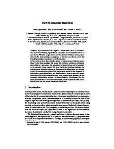
Intuitively, every so often, all nodes will collect a global snapshot S of the local states of all nodes. Then, all nodes inspect S for any inconsistencies. If any are found, all nodes reset their local state to some consistent state. Given a general Byzantine tolerant algorithm A0 , we construct an algorithm Byz-State-Check. Byz-State-Check gathers a global snapshot of the local states at each node and ensures that the local states are consistent. In addition if the states were consistent to start with, then Byz-State-Check does not alter them. That is, Byz-State-Check alters the local states to a consistent state, only if required. Figure 4 presents the algorithm Byz-State-Check. Algorithm Byz-State-Check
/* executed at node p*/
1. execute a Byzantine agreement on local state of A0 ; 2. ∆agree beats after the the beginning of the execution of line 1: (a) if S represents a legal state repair local state if it is inconsistent with S; (b) otherwise reset local state.
Fig. 4. A Byzantine tolerant state validation and reset. Remark 7. ∆agree is an upper bound on the number of rounds it takes to execute Byzantine agreement (2f + 3 for a typical efficient implementation). Since all correct nodes wait ∆agree beats from entering line 1 until entering line 2, it is ensured that all correct nodes enter line 2 after they see the same global snapshot S. Given a general Byzantine tolerant algorithm A0 , a [∆agree +1]-pulser P and a Byz-State-Check algorithm C, the algorithm SS-Byz-Stabilizer is constructed, as in Figure 5. Algorithm SS-Byz-Stabilizer
1. 2. 3. 4.
/* executed at each beat */ /* A0 is the algorithm to be stabilized */ /* C is an instance of Byz-State-Check*/ /* P is a [∆agree + 1]-pulser */
execute a single round of A0 ; execute a single round of C; execute a single beat of P; if P pulsed this beat re-initialize C.
Fig. 5. A Self-stabilizing Byzantine tolerant Stabilizer. Theorem 5. SS-Byz-Stabilizer transforms a Byzantine tolerant algorithm A0 into Self-stabilizing Byzantine tolerant algorithm. Proof. P is a [∆agree +1]-pulser. Hence, eventually it starts pulseing ∆agree +1 beats apart. When this happens, C is re-executed periodically, and terminates between such 2 executions . Hence, C performs correctly. This means that the local states of A0 will be consistent. And we have that starting from any initial state of A0 ’s local states, eventually A0 ’s local states are consistent. t u
On Self-stabilizing Synchronous Actions Despite Byzantine Attacks
10
15
Acknowledgments
We would like to thank Ariel Daliot for helpful discussions and insightful comments.
References 1. Y. Afek and S. Dolev. Local stabilizer. In Proc. of the 5th Israeli Symposium on Theory of Computing Systems (ISTCS97), Bar-Ilan, Israel, Jun 1997. 2. A. Arora, S. Dolev, , and M.G. Gouda. Maintaining digital clocks in step. Parallel Processing Letters, 1:11–18, 1991. 3. A. Daliot and D. Dolev. Self-stabilization of byzantine protocols. In In Proc. of the 7th Symposium on Self-Stabilizing Systems (SSS’05), Barcelona, Spain, Oct 2005. 4. A. Daliot, D. Dolev, and H. Parnas. Linear time byzantine self-stabilizing clock synchronization. In Proc. of 7th Int. Conference on Principles of Distributed Systems (OPODIS’03), La Martinique, France, Dec 2003. A corrected version appears in http://arxiv.org/abs/cs.DC/0608096. 5. D. Dolev. The byzantine generals strike again. Journal of Algorithms, 3:14–30, 1982. 6. D. Dolev, J. Y. Halpern, B. Simons, and R. Strong. Dynamic fault-tolerant clock synchronization. J. Assoc. Computing Machinery, 42(1):143–185, Jan 1995. 7. S. Dolev. Possible and impossible self-stabilizing digital clock synchronization in general graphs. Journal of Real-Time Systems, 12(1):95–107, 1997. 8. S. Dolev and J. L. Welch. Wait-free clock synchronization. Algorithmica, 18(4):486– 511, 1997. 9. S. Dolev and J. L. Welch. Self-stabilizing clock synchronization in the presence of byzantine faults. Journal of the ACM, 51(5):780–799, 2004. 10. A. S. Gopal and K. J. Perry. Unifying self-stabilization and fault-tolerance. In IEEE Proceedings of the 12th annual ACM symposium on Principles of distributed computing, Ithaca, New York, 1993. 11. T. Herman. Phase clocks for transient fault repair. IEEE Transactions on Parallel and Distributed Systems, 11(10):1048–1057, 2000. 12. E. N. Hoch, D. Dolev, and A. Daliot. Self-stabilizing byzantine digital clock synchronization. In Proc. of 8th International Symposium on Stabilization, Safety, and Security of Distributed Systems (SSS’06), Dallas, Texas, Nov 2006. 13. S. Katz and K. J. Perry. Self-stabilizing extensions for message-passing systems. Distributed Computing, 7(1):17–26, 1993. 14. M. Nesterenko and A. Arora. Dining philosophers that tolerate malicious crashes. In 22nd Int. Conference on Distributed Computing Systems, 2002. 15. M. Nesterenko and A. Arora. Tolerance to unbounded byzantine faults. In SRDS, pages 22–, 2002. 16. M. Papatriantafilou and P. Tsigas. On self-stabilizing wait-free clock synchronization. Parallel Processing Letters, 7(3):321–328, 1997. 17. Y. Sakurai, F. Ooshita, and T. Masuzawa. A self-stabilizing link-coloring protocol resilient to byzantine faults in tree networks. In OPODIS, pages 283–298, 2004.