IEEE TRANSACTIONS ON SIGNAL PROCESSING, VOL. 57, NO. 4, APRIL 2009
1383
On Spatial Aliasing in Microphone Arrays Jacek Dmochowski, Jacob Benesty, and Sofiène Affès
Abstract—Microphone arrays sample the sound field in both space and time with the major objective being the extraction of the signal propagating from a desired direction-of-arrival (DOA). In order to reconstruct a spatial sinusoid from a set of discrete samples, the spatial sampling must occur at a rate greater than a half of the wavelength of the sinusoid. This principle has long been adapted to the microphone array context: in order to form an unambiguous beampattern, the spacing between elements in a microphone array needs to conform to this spatial Nyquist criterion. The implicit assumption behind the narrowband beampattern is that one may use linearity and Fourier analysis to describe the response of the array to an arbitrary wideband plane wave. In this paper, this assumption is analyzed. A formula for the broadband beampattern is derived. It is shown that in order to quantify the spatial filtering abilities of a broadband array, the incoming signal’s bifrequency spectrum must be taken into account, particularly for nonstationary signals such as speech. Multi-dimensional Fourier analysis is then employed to derive the broadband spatial transform, which is shown to be the limiting case of the broadband beampattern as the number of sensors tends to infinity. The conditions for aliasing in broadband arrays are then determined by analyzing the effect of computing the broadband spatial transform with a discrete spatial aperture. It is revealed that the spatial Nyquist criterion has little importance for microphone arrays. Finally, simulation results show that the well-known steered response power (SRP) method is formulated with respect to stationary signals, and that modifications are necessary to properly form steered beams in nonstationary signal environments. Index Terms—Beamforming, broadband beampattern, microphone arrays, spatial aliasing, spatial sampling, wavenumber-frequency spectrum.
I. INTRODUCTION IGNAL processing is ultimately about the collection of data from the physical world for the sake of extracting relevant information about the processes which brought about the measured signals. Multiple sensors are commonly employed in order to enhance this extraction process through the spatial diversity provided by sensors at different spatial locations. Array signal processing [1] techniques intelligently combine the outputs of the various sensors in a process, termed beamforming, aimed at cleaning the received signals from the contaminating interference and noise.
S
Manuscript received March 27, 2008; revised October 01, 2008. First published December 09, 2008; current version published March 11, 2009. The associate editor coordinating the review of this manuscript and approving it for publication was Dr. Wing-Kin Ma. J. Dmochowski was with the Université du Québec, INRS-EMT, Montréal, QC H5A 1K6, Canada. He is now with the Department of Biomedical Engineering , City College of New York, City University of New York, New York, NY 10031 USA (e-mail:
[email protected]). J. Benesty and S. Affès are with the Université du Québec, INRS-EMT, Montréal, QC H5A 1K6, Canada. Digital Object Identifier 10.1109/TSP.2008.2010596
This paper is about broadband arrays: sensor arrays which are designed to pick up temporally broadband signals. To date, there are two main applications of such arrays: antenna arrays which capture broadband wireless signals, and microphone arrays which sample naturally broadband sounds. While the former is certainly an active research area, this paper focuses on microphone arrays for several reasons. First of all, the capture of sound nicely illustrates the concepts of broadband array processing. Second, the microphone array environment is much harsher due to the analog nature of the signal and the long reverberation times of common enclosures. As a result, microphone arrays exhibit relatively poor performance in real environments [2]. The classical theory of beamforming dates back to the mid-tolate twentieth century, with the most prominent advances found in [3]–[5]; good overviews of the area are provided by [6] and [7]. Microphone arrays emerged somewhat later, with early and notable works found in [8]–[13]. Much like temporal signals are decomposed into a linear combination of sinusoids via Fourier analysis, space–time fields may be decomposed into an infinite summation of monochromatic plane waves—the energy of each component monochromatic wave is focused at a single temporal frequency. The fundamental premise here is that by characterizing the response of a space–time filter (i.e., a beamformer) to a particular monochromatic signal, one may use the linearity of the space–time Fourier transform to characterize the response of the array to a general broadband signal. One example of the application of this principle occurs with spatial aliasing [1]: in order to reconstruct a monochromatic signal from a set of spatial samples (i.e., with uniform sampling occurring along one spatial dimension), the sampling period must be equal to less than half of the wavelength corresponding to the monochromatic wave. The theory of spatial aliasing pertaining to monochromatic signals is well covered in [1]. Microphone signals are naturally broadband, and as a result, the spatial sampling theorem requires careful thought in this context. Most treatments covering spatial aliasing in microphone arrays work within the monochromatic framework; refer to [14] and [15], for example. The implication here is that in order to prevent spatial aliasing, one should sample at half of the wavelength corresponding to the smallest wavelength (or highest temporal frequency) of interest. The resulting arrays are very limited in spatial extent—for example, a two-element array should be spaced only 4.25 cm to prevent aliasing for up to 4 kHz—clearly, spatial aliasing is somewhat of a misunderstood phenomenon, since the human binaural auditory system does not experience problems localizing broadband sounds with an average spacing of 20 cm (corresponding to aliasing above 850 Hz!). Indeed, the most reliable cues used by humans for localization of sounds are the interaural
1053-587X/$25.00 © 2009 IEEE Authorized licensed use limited to: Inst Natl de la Recherche Scientific EMT. Downloaded on March 18, 2009 at 08:17 from IEEE Xplore. Restrictions apply.
1384
IEEE TRANSACTIONS ON SIGNAL PROCESSING, VOL. 57, NO. 4, APRIL 2009
time difference (ITD) and interaural intensity difference (IID). It is well known that our auditory system, with ITD only, is unable to localize a pure tone when its frequency is about 800 Hz and above [16]. This is due to the classical spatial sampling theorem. However, many experiments show that with more “complex” signals (such as speech or sounds that cover a reasonable frequency range), our auditory system is able to remarkably resolve the phase ambiguity and localize quite precisely with ITD only [16]. Motivated by these fundamental observations, in the following, the meaning of spatial aliasing when operating a broadband array is examined. This paper is structured as follows. In Section II, a definition of the broadband beampattern is derived, and an example employing the uniform linear array (ULA) is provided. Section III develops the aliasing conditions for broadband arrays with the help of wavenumber-frequency analysis. Theoretical broadband beampatterns for signals of varying bandwidth are shown in Section IV. To verify the proposed claims, simulation results are presented in V. Finally, concluding remarks are made in Section VI.
form of a second-order process is given by
whose covariance function [19], [20], [23]
(2) with probability one, where denotes temporal frequency, denotes time, and may be viewed as a complex-valued random measure. Equation (2) expresses a stochastic process as a summation of infinitely many randomly and infinitesimally weighted complex exponentials, in a manner analogous to how the standard Fourier transform expresses a deterministic function as a superposition of weighted complex exponentials. The Loève bifrequency spectrum, also referred to as the bifrequency spectral correlation function, generalized spectrum, and cointensity spectrum is formally defined as (3) where
denotes complex conjugation and (4)
II. BROADBAND BEAMPATTERN AND BROADBAND STEERED RESPONSE POWER Microphone arrays are targeted towards the capture, enhancement, and localization of speech [17]. Moreover, speech is widely recognized as a nonstationary random process [18]. In this section, a definition of the broadband beampattern which takes into account the nonstationary nature of speech is presented. It will be shown that a frequency-domain statistic termed the “bifrequency spectrum” plays a key role in this definition. Before providing the definition, some mathematical preliminaries required for the spectral characterization of nonstationary random processes are given. A. Bifrequency Spectrum The notion of the bifrequency spectrum is relatively unknown in the microphone-array research community. A rigorous definition of the bifrequency spectrum requires the understanding of several related ideas. This section begins by defining the concept of a harmonizable covariance function, and subsequently, a harmonizable stochastic process. is A covariance function termed harmonizable if there exists a frequency-domain, comdefined on plex-valued covariance function such that [19], [20] (1) where the integral is recognized as the Fourier-Stieltjes transform [21], and denote time instants, and denote temporal frequencies, and . This integral may also be interpreted in the Lebesgue [22] sense, in which case corresponds to a complex-valued measure. 1 is said to be (strongly) A second-order random process harmonizable if we can write it as the Fourier–Stieltjes trans1A random process is said to be second-order if its second order covariance function R (t ; t ) = E fx(t )x (t )g exists and is finite for all t and t .
which is assumed to exist in the is the Fourier transform of sense of distributions [24], [25] for almost all realizations of the . process The following relations between the quantities (1)–(4) hold in the sense of distributions [19], [24]–[26]: (5) (6) Mathematical rigor aside, it is important to relate the notion of the bifrequency spectrum to the nonstationarity of a random process. For wide-sense stationary (WSS) processes, the bifrequency spectrum reduces to (7) where is the power spectral density (PSD) or equivalently, the Fourier transform of the auof a WSS tocorrelation function . Thus, for stationary random processes, two disprocess tinct Fourier coefficients are statistically uncorrelated. However, for nonstationary random processes, the bifrequency spectrum will exhibit nonzero correlations along so-called support curves . Thus, one [19], [20], [27] other than the main diagonal way of detecting nonstationarity of a random process is to detect the presence of interfrequency correlations—refer to [19] and the references therein. Finally, the bifrequency spectrum possesses a normalized variant termed the spectral coherence [20] (8) which is upper-bounded in magnitude by 1 due to the Schwarz inequality.
Authorized licensed use limited to: Inst Natl de la Recherche Scientific EMT. Downloaded on March 18, 2009 at 08:17 from IEEE Xplore. Restrictions apply.
DMOCHOWSKI et al.: ON SPATIAL ALIASING IN MICROPHONE ARRAYS
1385
B. Broadband Beampattern The source signal is modeled as a wideband and harmonizable (potentially nonstationary) random process. Consider a discrete aperture consisting of an array of sensors that sample the wave field in space and time. Assume that a plane wave impinges on the array from direction , where it is assumed that the source lies on the same plane as the array. The plane wave is assumed to be a broadband signal such that the response to this signal characterizes the “broadband beampattern” of the array. The output of the th sensor at time is modeled as (9) where is the output of sensor at time , is the harmonizable process characterizing the source signal, is the propagation time from the source to sensor , and is the DOA of the source. It should be pointed out that noise is neglected as it is irrelevant in the characterization of the beampattern, and that is also a harmonizable nonstationary process. Invoking (4), we may express (9) in the frequency domain as (10) where
A beamformer steered to a DOA applies a complex weight to each sensor and then sums across the aperture to form the beamformer output
(11) where is the beamformer output at frequency , notes the conjugate transpose of a matrix or vector,
de-
is termed the steered response pattern which is plotted as a function of the steered DOA . In the time domain, the beamformer output is written as
(13) One would like to quantify the average energy of the incoming wavefield as a function of the DOA. To that end, the instantaneous power of the beamformer output is
(14) The quantity in (14) refers to the broadband steered pattern of the array, where it is assumed that is fixed and the independent variable is the steered angle . For a characterization of the broadband beampattern, we simply fix and vary , with the but this broadband beampattern still denoted by time being a function of . For a conventional (delay-and-sum) beamformer, the two are equivalent, and thus, throughout this paper, we use the terms interchangeably when referring to (14). refers to the broadband beamWhen the quantity varies), it characterizes beampattern (i.e., is fixed but forming abilities; on the other hand, DOA estimation abilities when viewed as the broadband are captured by steered pattern (i.e., varies but is fixed). It can be seen that aside from the steering vector, in order to define the array’s broadband beampattern, the incoming signal’s bifrequency spectrum needs to be specified. For a WSS source signal, the broadband beampattern reduces to (15)
is the vector of beamforming weights applied at frequency , denotes the transpose of a matrix or vector,
and
is termed the steering vector. The PSD of the beamformer output follows as
(12) where is the PSD of the source is referred to as the and the quantity is fixed and the innarrowband beampattern when dependent variable is . Conversely, if we fix , then
meaning that the broadband beampattern is a superposition of the individual narrowband beampatterns weighted by the PSD of the source. However, when the source signal is nonstationary, the bifrequency spectrum cross-combines the narrowband beampatterns across different frequencies before forming the broadband beam. It is also interesting to point out that in this case, the broadband beampattern is a function of time . This represents a departure from conventional array notions which have customarily assumed stationary signals without loss of generality. Clearly, for nonstationary signals such as speech, the narrowband beampattern must be coupled with bifrequency analysis in order to have an idea of the broadband beam, which is of utmost importance. By themselves, the narrowband beampatterns do not convey enough to capture the spatial filtering operation of the array. In practice, even when considering stationary signals, the impact of the bifrequency spectrum on the resulting broadband beampattern needs to be taken into account. Over a finite length
Authorized licensed use limited to: Inst Natl de la Recherche Scientific EMT. Downloaded on March 18, 2009 at 08:17 from IEEE Xplore. Restrictions apply.
1386
IEEE TRANSACTIONS ON SIGNAL PROCESSING, VOL. 57, NO. 4, APRIL 2009
observation window, the correlations between the various distinct frequencies will not be exactly zero—these interfrequency correlations only tend to zero as the observation window length tends to infinity. For example, [20] plots a sample bifrequency spectrum for a finite white noise sequence and observes significant nonzero correlations off the main diagonal. Many microphone array applications employ short frame sizes; as a result, the bifrequency spectrum will have a significant effect on the resulting broadband beampattern. C. Broadband Beampattern of a Uniform Linear Array
Since the autocorrelation function in (23) may not be expressed , it is nonstationary. as a function of a single argument The corresponding bifrequency spectrum is written as [28] (see the Appendix for a correction):
(24) Now consider a signal formed by a linear combination of sinusoids:
Consider a conventional delay-and-sum beamformer which selects the weights according to (16)
(25) The bifrequency spectrum of this signal is given by
Furthermore, assume a ULA, such that the steering vector is given by
(17)
(26)
where is the intersensor distance and the speed of propagation. The resulting beampattern is given by
Substituting (26) into (20) leads to the following expression for the broadband beampattern of a ULA:
(18) Using the formula for the geometric progression, the beampattern may be expressed as (19) Substituting (19) into (14) results in the general expression for the broadband beampattern of a ULA
(20) where
(21)
(27)
III. SPATIAL ALIASING IN BROADBAND ARRAYS In this section, the meaning of aliasing in broadband arrays is examined. To facilitate the analysis, the wavenumber-frequency spectrum is employed to derive what is termed therein as the “broadband spatial transform.” It is shown that this transform is indeed the limiting case of the broadband beampattern as the number of sensors tends to infinity. Based on the broadband spatial transform, a rigorous definition of aliasing is provided, and the conditions for aliasing with both monochromatic and wideband signals are derived. A. Wavenumber-Frequency Spectrum
D. Bifrequency of Sinusoidal Signals Consider a source signal of the form (22) The autocorrelation function of this signal is given by [28]
The standard one-dimensional Fourier transform expresses a temporal signal as a linear combination of sinusoidal signals. Similarly, an arbitrary space–time field may be expressed as a superposition of monochromatic plane waves via the multi-dimensional Fourier transform. The four-dimensional Fourier transform of a space–time signal is referred to as the wavenumber-frequency spectrum and is given by [1]
(23) Authorized licensed use limited to: Inst Natl de la Recherche Scientific EMT. Downloaded on March 18, 2009 at 08:17 from IEEE Xplore. Restrictions apply.
(28)
DMOCHOWSKI et al.: ON SPATIAL ALIASING IN MICROPHONE ARRAYS
1387
where are the frequency-domain weights, is the and time , value of the signal at position is the wavenumber vector, and denotes angular frequency. The wavenumber is the spatial frequency vector and may be expressed as (29)
(i.e., sensors) and time-aligned with respect to the origin. Therefore, one can infer that the output of a delay-and-sum beamformer with an infinitely large aperture corresponds to an estimate of the wavenumber-frequency spectrum averaged as the over the temporal frequency range. We refer to broadband spatial transform (BST). Furthermore, the mean-squared of (32) is given by
where is a unit vector pointing in the direction specified by elevation and azimuth which refers to the direction of the plane wave . Notice that the wavenumber-frequency spectrum may also be expressed as the following spatial Fourier transform: (30) where is the temporal Fourier transform of the signal observed at position . The inverse wavenumber-frequency transform expresses the space–time field as a weighted linear combination of plane waves [1]
(33) where is the spatiotemporal autocorrelation function of the space–time field and we have dropped the dependence of on and . is a plane-wave propIf one assumes that the field , then one may write agating with direction-of-arrival the space–time signal as the one-dimensional function . As a result (34)
(31) The resulting steered response power is written as B. Broadband Spatial Transform Notice that the wavenumber vector is a function of the temporal frequency in its magnitude only—the spatial inwhich is formation is conveyed by the unit vector specified by the azimuth and elevation of the corresponding spatial frequency vector. Note also that for broadband arrays, we are mostly interested in the spatial component of the wavenumber-frequency spectrum; one would like to quantify the level of the spatial spectrum independently of the temporal frequency . One way of doing this is to integrate the wavenumber-frequency spectrum over the temporal frequency range, which is straightforward since only the magnitude of the wavenumber needs to be integrated across. To that end, we define
(35) . From (35), it is interwhere esting to note the dependence of the mean square of the BST, a spatial statistic, on the temporal autocorrelation function of the . source signal Assume now that the correlation function in (35) is harmonizable; then, we may write
(36) Substituting (36) into (35) results in (37), shown at the bottom of the next page. Notice that the term
(32) Consider (32): the temporal argument is equal to the relative delay (temporal lag) between position and the origin, assuming that the incoming wavefront is planar. Thus, (32) is precisely the form of the delay-and-sum beamformer computed over an infinite set of spatial samples
may be viewed as the limiting case of the inner product as the number of sensors tends to infinity, with the exception that the DOA in the continuous case is two-dimensional. Thus, we may claim that
Authorized licensed use limited to: Inst Natl de la Recherche Scientific EMT. Downloaded on March 18, 2009 at 08:17 from IEEE Xplore. Restrictions apply.
(38)
1388
IEEE TRANSACTIONS ON SIGNAL PROCESSING, VOL. 57, NO. 4, APRIL 2009
where the steered azimuth has been set to to enable full equivalence. Therefore, the mean square of the BST is equal to the limiting case of the broadband beampattern as the number of sensors tends to infinity. Aliasing is a phenomenon that results from computing a discrete estimate of a continuous Fourier transform. After sampling, the discrete spectrum becomes periodic with the sampling frequency. Aliasing occurs when the bandwidth of the signal exceeds half of the period of the discrete spectrum. Intuitively, in analyzing spatial aliasing in microphone arrays, one needs to analyze the periodicity of the discrete version of the continuous BST (32), which is given by
To ease analysis, assume that the source lies on the - plane, and we are only concerned with the azsuch that imuthal component of the spatial spectrum
(39)
(46)
is the th spatial sample and it should be noted that where space is discrete but time need not be for the sake of the analysis. For a single plane-wave propagating with DOA , the discrete BST is given by
(45) Next, one can apply the following result regarding a summation of complex exponentials:
Substituting (46) into (45)
(40)
(47)
In the following, the aliasing conditions for both narrowband and wideband signals are derived.
Consider now the conditions for the argument of the delta Dirac function in (47) to equal zero. This requires
C. Monochromatic Signal
(48)
Consider a monochromatic source signal which is equivalent to (41) is the temporal frequency of the signal and where wave’s DOA. Substituting (41) into (40) results in
(49)
is the where if
is the wavelength. For , meaning that
, (49) holds
(42) (50) If we further assume that the spatial sampling is in the -direction only and with a sampling period of : (43)
which is the desired result; indeed, this is the true (nonaliased) spectral peak. Spatial aliasing may now be rigorously defined: aliasing occurs whenever such that
then (44)
(51)
In other words, aliasing is a result of the argument of the deltaDirac function in (47) going to zero even though the argument
(37)
Authorized licensed use limited to: Inst Natl de la Recherche Scientific EMT. Downloaded on March 18, 2009 at 08:17 from IEEE Xplore. Restrictions apply.
DMOCHOWSKI et al.: ON SPATIAL ALIASING IN MICROPHONE ARRAYS
1389
does not match the true DOA . Note also that the steered , and that the cosine function is range for a ULA is one-to-one over this interval. Thus (60) (52) One can now determine the aliasing conditions. Under the monochromatic assumption, the BST tends to infinity if there such that exists an integer
Examining (60), it is interesting to note that the discrete BST for an arbitrary wideband signal takes the form of a series of temporal Fourier coefficients. For any temporal signal which obeys
(53)
(61)
or (54) Take
; we know that over our unique range
one can state that the BST exhibits an infinite peak only when the scaling factor (62)
, (55)
meaning that to prevent aliasing, one needs to ensure that (56) or (57) which is indeed the classical narrowband aliasing criterion. Note , the condition (57) also prevents (53). that for D. Broadband Signal Consider a signal of the form (58) which is a plane-wave signal whose temporal frequency content ] and presumably wideband. Again is arbitrary [defined by assuming a one-dimensional sampling scheme and considering , the continuous BST only spatial frequencies with of this signal is given by (59) The discrete version of (60) is obtained by sampling space; in : other words, we set
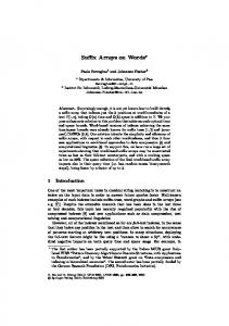
. Thus, for wideband signals with spectra which implies of the form (61), spatial aliasing does not result, regardless of the spatial sampling period. The condition of (61) refers to signals with two basic properties; first of all, the signal must be bandlimited. If not, the summation is not finite. Secondly, the signal must not have strong harmonic components at integer multiples of the fundamental . The presence of such frequency harmonic components may drive the BST to infinity at DOAs not matching the true DOA. IV. THEORETICAL BEAMPATTERNS Fig. 1 illustrates the broadband beampatterns for a signal of the form (25) with , consisting of tones uniformly spaced from 1000 to 2000 Hz. A ULA is assumed to compute the beampatterns; the source impinges on the array at an azimuth of 73 degrees. The intersensor distance is which means that all tones comprising the signal lead to spa, tial aliasing. The plots are shown for , the signal consists of a tone at 2000 Hz. The where for . To highlight beampatterns are shown at time 0: the effect of signal nonstationarity on the resulting broadband steered patterns, the plots also show the broadband patterns not taking into account the cross-terms; in other words, the quantity of (15) is also displayed. It is evident that by increasing , the alias formed at 135 deis diminished as more tones are introduced into grees for , the alias is indistinguishable from the signal. With the background. Since the aliases occur at different azimuths for different frequencies, the integrated broadband beampattern tends to average out the sidelobes (i.e., destructive summation). The bifrequency spectrum of the source signal further shapes the steered patterns as the “cross-beampattern” terms provide even greater suppression of the sidelobes. Notice that the averaging effect becomes significant at only ten tones. Furthermore, notice the narrowing of the main lobe as we introduce additional harmonics to the signal. In general, the broadband beampattern attains greater directivity as the bandwidth of the signal increases.
Authorized licensed use limited to: Inst Natl de la Recherche Scientific EMT. Downloaded on March 18, 2009 at 08:17 from IEEE Xplore. Restrictions apply.
1390
IEEE TRANSACTIONS ON SIGNAL PROCESSING, VOL. 57, NO. 4, APRIL 2009
Fig. 1. Steered response patterns of a real signal consisting of all aliased frequencies: (a) 1 tone, (b) 2 tones, (c) 3 tones, (d) 5 tones, (e) 10 tones, (f) 100 tones. The classical aliasing effect diminishes with the inclusion of additional harmonics in the signal. The nonstationarity of the signal further reduces the sidelobe height.
Fig. 1. (Continued.) Steered response patterns of a real signal consisting of all aliased frequencies: (a) 1 tone, (b) 2 tones, (c) 3 tones, (d) 5 tones, (e) 10 tones, (f) 100 tones. The classical aliasing effect diminishes with the inclusion of additional harmonics in the signal. The nonstationarity of the signal further reduces the sidelobe height.
Fig. 2 plots the broadband beampatterns for an intersensor , meaning that all of the signal’s distance of frequencies are nonaliased. In this case, the effect of adding tones to the signal is only slightly beneficial—the width of the main lobe is gradually reduced as the signal bandwidth increases. However, it seems that increasing sensor spacing provides clear benefits for wideband array processing without incurring aliasing.
Fig. 3 depicts the narrowband beampatterns across the 1000–2000-Hz range for the ULA with a spacing of . The aliasing effect is present across the entire frequency range, in that the sidelobes attain the same height as the main lobe. However, as we integrate across the temporal frequencies taking into account the bifrequency spectrum, the resulting broadband beampatterns exhibit a clearly unambiguous broadband beam.
Authorized licensed use limited to: Inst Natl de la Recherche Scientific EMT. Downloaded on March 18, 2009 at 08:17 from IEEE Xplore. Restrictions apply.
DMOCHOWSKI et al.: ON SPATIAL ALIASING IN MICROPHONE ARRAYS
1391
Fig. 2. Steered response patterns of a real signal consisting of all nonaliased frequencies: (a) 1 tone, (b) 2 tones, (c) 3 tones, (d) 5 tones, (e) 10 tones, (f) 100 tones. The broadband steered pattern’s mainlobe width diminishes as the bandwidth of the signal increases. Comparing to Fig. 1, increasing the microphone spacing leads to clear benefits in broadband applications without incurring aliasing.
Fig. 2. (Continued.) Steered response patterns of a real signal consisting of all nonaliased frequencies: (a) 1 tone, (b) 2 tones, (c) 3 tones, (d) 5 tones, (e) 10 tones, (f) 100 tones. The broadband steered pattern’s main lobe width diminishes as the bandwidth of the signal increases. Comparing to Fig. 1, increasing the microphone spacing leads to clear benefits in broadband applications without incurring aliasing.
Fig. 4 displays the narrowband beampatterns for the ULA . Notice that the “spectral tilt” with a spacing of effect (i.e., the beam narrows as frequency increases) is clearly observed in Fig. 4 but only marginally present in Fig. 3.
is performed. The simulations employ a ULA of elements and an interelement spacing given by 0.34 m. This corresponds to narrowband aliasing above 500 Hz. The signal is a superposition of sinusoidal signals as shown , ranging from 1000 to 2000 Hz, in (25) with and varying from 1 to 100. The microphones are sampled at 48 kHz. Assuming the third (center) microphone is set as the origin, the source is located at ( 2.45,8,0) m—this corresponds
V. EXPERIMENTAL STUDY In order to further investigate the theoretical results derived above, a computer simulation modeling anechoic propagation
Authorized licensed use limited to: Inst Natl de la Recherche Scientific EMT. Downloaded on March 18, 2009 at 08:17 from IEEE Xplore. Restrictions apply.
1392
IEEE TRANSACTIONS ON SIGNAL PROCESSING, VOL. 57, NO. 4, APRIL 2009
, is a where function that translates the steered DOA to the relative delay experienced between microphones and : (64)
Fig. 3. Narrowband beampatterns for aliased temporal frequencies. Even though aliasing is present across the entire temporal frequency range, the location of the main alias varies with the temporal frequency. When integrating to obtain the broadband beampattern, the aliasing phenomenon is eliminated.
and the summation in (63) is usually taken over the set of unique . In the implementation, the cross-corremicrophone pairs lations are upsampled (and interpolated) by a factor of 20 to allow for smooth steered response patterns. A single “frame” of 2 s is employed to compute the cross-correlation estimates. Fig. 5 displays the obtained experimental broadband steered response patterns for the various values of . The resulting beampatterns strongly resemble those in Fig. 1 which do not take into account the bifrequency spectrum. In other words, the SRP algorithm conveys only the stationary component of the steered response power. This is somewhat problematic as SRP is generally accepted as the most reliable algorithm for the localization of speech, which is nonstationary. Indeed, for a WSS signal, the mean-square of the BST reduces to
(65)
Fig. 4. Narrowband beampatterns for nonaliased temporal frequencies. The small array size prevents narrowband aliasing, but also emphasizes the spectral tilt effect: the main lobe width decreases with increased frequency.
where to and
which reduces under stationarity,
(66) to . As the source and microphones lie on a 2-dimensional plane, the location space is confined to the set of azimuth angles (0,179) degrees with a resolution of 1 degree. The impulse response from the source to each microphone is computed using the image method model of [31], with all reflection coefficients (i.e., walls, ceiling, and floor) set to zero to simulate anechoic propagation. The clean signal is convolved with the synthetic impulse responses to generate the microphone data. Since the purpose of the simulations is to compute experimental broadband beampatterns, noise is not added to the microphones. In the experiment, the steered response power (SRP) algorithm [29], [30] is utilized to estimate the broadband steered pattern. The SRP algorithm is a direct estimate of (33)—the algorithm computes, for each candidate DOA, the following sum:
(63)
by definition. Thus, the SRP algorithm fails to capture the bifrequency (nonstationary) portion of the broadband steered response. Lastly, the experiment is repeated with a two-second female English speech signal. Fig. 6 shows the experimental SRP: it is clear that the resulting steered pattern is not negatively impacted by sampling at a sub-Nyquist rate. The power spectral density of the speech signal used in the simulation is shown in Fig. 6(b), where the narrowband aliasing cutoff frequency of 500 Hz is indicated. It appears that a variant of SRP which does not make the WSS assumption is needed to provide more accurate estimates of the broadband steered response pattern, and consequently, the location estimates. Indeed, Figs. 5 and 6 are missing their nonstationary counterparts as an algorithm to estimate the more general broadband steered response power does not exist. The development of a suitable algorithm is the subject of current work.
Authorized licensed use limited to: Inst Natl de la Recherche Scientific EMT. Downloaded on March 18, 2009 at 08:17 from IEEE Xplore. Restrictions apply.
DMOCHOWSKI et al.: ON SPATIAL ALIASING IN MICROPHONE ARRAYS
Fig. 5. Experimental steered response patterns of a real signal consisting of all aliased frequencies: (a) 1 tone, (b) 2 tones, (c) 3 tones, (d) 5 tones, (e) 10 tones, (f) 100 tones. Careful examination of the plots in comparison with Fig. 1 reveals that the SRP method fails to capture the bifrequency terms present with a nonstationary signal.
VI. CONCLUSION This paper has proposed a definition of the broadband beampattern. It was shown that in order to characterize the time-domain response of a microphone array to an impinging broadband plane wave signal, the signal’s bifrequency spectrum must be considered. The BST was derived as the limiting case of the
1393
Fig. 5. (Continued.) Experimental steered response patterns of a real signal consisting of all aliased frequencies: (a) 1 tone, (b) 2 tones, (c) 3 tones, (d) 5 tones, (e) 10 tones, (f) 100 tones. Careful examination of the plots in comparison with Fig. 1 reveals that the SRP method fails to capture the bifrequency terms present with a nonstationary signal.
broadband beampattern as the number of sensors tends to infinity. The aliasing conditions in broadband arrays were then derived based on the effect of estimating the BST with a discrete aperture. Unless a wideband signal possesses a strong harmonic component, spatial aliasing is not experienced with broadband signals. It was also revealed that the well-known and extensively
Authorized licensed use limited to: Inst Natl de la Recherche Scientific EMT. Downloaded on March 18, 2009 at 08:17 from IEEE Xplore. Restrictions apply.
1394
IEEE TRANSACTIONS ON SIGNAL PROCESSING, VOL. 57, NO. 4, APRIL 2009
By definition, the bifrequency spectrum is given by
(69) , where
Since otherwise
(70)
one obtains
(71)
REFERENCES
Fig. 6. (a) Experimental steered response pattern of a speech signal with a 34-cm sensor spacing and (b) power spectral density of speech signal. A significant portion of the signal’s energy falls above the spatial Nyquist cutoff frequency of 500 Hz; however, due to the broadband and nonstationary nature of speech, the broadband steered pattern shows no aliasing artifacts.
used SRP algorithm captures only the stationary portion of the broadband steered response pattern. More generally, the results of this paper point to a need to analyze broadband arrays in a distinct fashion to their narrowband counterparts. One cannot simply “superimpose” narrowband array results onto broadband arrays without careful thought. APPENDIX Consider a source signal of the form: (67) The corresponding Fourier transform is written as (68)
[1] D. H. Johnson and D. E. Dudgeon, Array Signal Processing. Englewood Cliffs, NJ: Prentice-Hall, 1993. [2] J. Benesty, J. Chen, Y. Huang, and J. Dmochowski, “On microphone-array beamforming from a MIMO acoustic signal processing perspective,” IEEE Trans. Audio, Speech, Lang. Process, vol. 15, pp. 1053–1065, Mar. 2007. [3] J. Capon, “High resolution frequency-wavenumber spectrum analysis,” Proc. IEEE, vol. 57, pp. 1408–1418, Aug. 1969. [4] O. L. Frost, III, “An algorithm for linearly constrained adaptive array processing,” Proc. IEEE, vol. 60, pp. 926–935, Aug. 1972. [5] L. J. Griffiths and C. W. Jim, “An alternative approach to linearly constrained adaptive beamforming,” IEEE Trans. Antennas Propag., vol. AP-30, pp. 27–34, Jan. 1982. [6] B. D. Van Veen and K. M. Buckley, “Beamforming: A versatile approach to spatial filtering,” IEEE ASSP Mag., vol. 5, pp. 4–24, Apr. 1988. [7] H. Krim and M. Viberg, “Two decades of array signal processing research: The parametric approach,” IEEE Signal Process. Mag., vol. 13, pp. 67–94, Jul. 1996. [8] J. L. Flanagan, J. D. Johnson, R. Zahn, and G. W. Elko, “Computersteered microphone arrays for sound transduction in large rooms,” J. Acoust. Soc. Amer., vol. 75, pp. 1508–1518, Nov. 1985. [9] H. Cox, R. M. Zeskind, and M. M. Owen, “Robust adaptive beamforming,” IEEE Trans. Acoust. Speech, Signal Process., vol. ASSP-35, pp. 1365–1376, Oct. 1987. [10] J. L. Flanagan, D. A. Berkeley, G. W. Elko, J. E. West, and M. M. Sondhi, “Autodirective microphone systems,” Acustica, vol. 26, pp. 58–71, Feb. 1991. [11] W. Kellermann, “A self-steering digital microphone array,” in Proc. IEEE Int. Conf. Acoustics, Speech, Signal Processing (ICASSP), 1991, vol. 5, pp. 3581–3584. [12] D. B. Ward, R. C. Williamson, and R. A. Kennedy, “Broadband microphone arrays for speech acquisition,” Acoust. Australia, vol. 26, pp. 17–20, Apr. 1998. [13] O. Hoshuyama, A. Sugiyama, and A. Hirano, “A robust adaptive beamformer for microphone arrays with a blocking matrix using constrained adaptive filters,” IEEE Trans. Signal Process., vol. 47, no. 10, pp. 2677–2684, Oct. 1999. [14] T. D. Abhayapala, R. A. Kennedy, and R. C. Williamson, “Spatial aliasing for near-field sensor arrays,” Electron. Lett., vol. 35, pp. 764–765, May 1999. [15] B. Rafaely, B. Weiss, and E. Bachmat, “Spatial aliasing in spherical microphone arrays,” IEEE Trans. Signal Process., vol. 55, no. 3, pp. 1003–1010, Mar. 2007. [16] B. C. J. Moore, An Introduction to the Psychology of Hearing, 4th ed. London, U.K.: Academic, 1997. [17] J. Benesty, J. Chen, and Y. Huang, Microphone Array Signal Processing. Berlin, Germany: Springer-Verlag, 2008. [18] D. O’Shaugnessy, Speech Communications: Human and Machine. New York: IEEE Press, 2000.
Authorized licensed use limited to: Inst Natl de la Recherche Scientific EMT. Downloaded on March 18, 2009 at 08:17 from IEEE Xplore. Restrictions apply.
DMOCHOWSKI et al.: ON SPATIAL ALIASING IN MICROPHONE ARRAYS
[19] A. Napolitano, “Uncertainty in measurements on spectrally correlated stochastic processes,” IEEE Trans. Signal Process., vol. 49, no. 9, pp. 2172–2191, Sep. 2003. [20] N. L. Gerr and J. C. Allen, “The generalized spectrum and spectral coherence of a harmonizable time series,” Digit. Signal Process., vol. 4, pp. 222–238, 1994. [21] M. Loève, Probability Theory. Princeton, NJ: Van Nostrand, 1963. [22] W. Rudin, Principles of Mathematical Analysis. New York: McGraw-Hill, 1976. [23] H. Hindberg and A. Hanssen, “Generalized spectral coherence for complex-valued harmonizable processes,” IEEE Trans. Signal Process., vol. 55, no. 6, pp. 2407–2413, Jun. 2007. [24] D. C. Champeney, A Handbook of Fourier Theorems. New York: Cambridge Univ. Press, 1990. [25] A. H. Zemanian, Distribution Theory and Transform Analysis. New York, Dover: , 1987. [26] H. Ogura, “Spectral representation of a periodic nonstationary random process,” IEEE Trans. Inf. Theory, vol. 17, pp. 143–149, Mar. 1971. [27] A. Napolitano, “Mean-square consistent estimation of the spectral correlation density for spectrally correlated stochastic processes,” in Proc. IEEE Int. Conf. Acoustics, Speech, Signal Processing (ICASSP), 2007, vol. 3, pp. 977–980. [28] A. G. Piersol and J. S. Bendat, Random Data. New York: Wiley, 2000. [29] M. Omologo and P. G. Svaizer, “Use of the cross-power-spectrum phase in acoustic event localization,” ITC-IRST Tech. Rep. 9303-13, 1993. [30] J. Dibiase, H. F. Silverman, and M. S. Brandstein, “Robust localization in reverberant rooms,” in Microphone Arrays: Signal Processing Techniques and Applications, M. S. Brstein and D. B. Ward, Eds. Berlin, Germany: Springer-Verlag, 2001, pp. 157–180. [31] J. B. Allen and D. A. Berkley, “Image method for efficiently simulating small-room acoustics,” J. Acoust. Soc. Amer., vol. 65, pp. 943–950, Apr. 1979.
Jacek Dmochowski was born in Gdansk, Poland, in 1979. He received the Bachelor’s of Engineering degree (with High Distinction in Communications Engineering), the Master’s of Applied Science degree in electrical engineering from Carleton University, Ottawa, Canada, and the Ph.D. degree in Telecommunications (granted ‘‘exceptionnelle’’) from the University of Quebec—INRS-EMT, in 2003, 2005, and 2008, respectively. He is currently a Research Scholar at the Biomedical Engineering Department of the City College of New York, City University of New York, and is the recipient of the National Sciences and Engineering Research Council (NSERC) of Canada Post-Doctoral Fellowship (2008–2010). His research interests lie in the area of multichannel digital signal processing and include machine learning of neural signals, as well as beamforming, localization, and separation of acoustic and biomedical signals.
1395
Jacob Benesty was born in 1963. He received the Master’s degree in microwaves from Pierre & Marie Curie University, France, in 1987 and the Ph.D. degree in control and signal processing from Orsay University, France, in April 1991. During the Ph.D. program (from November 1989 to April 1991), he worked on adaptive filters and fast algorithms at the Centre National d’Etudes des Telecommunications (CNET), Paris, France. From January 1994 to July 1995, he worked at Telecom Paris University on multichannel adaptive filters and acoustic echo cancellation. From October 1995 to May 2003, he was first a Consultant and then a Member of the Technical Staff at Bell Laboratories, Murray Hill, NJ. In May 2003, he joined the University of Quebec, INRS-EMT, Montreal, QC, Canada, as an Associate Professor. He coauthored the books Acoustic MIMO Signal Processing (Berlin, Germany: Springer-Verlag, 2006) and Advances in Network and Acoustic Echo Cancellation (Berlin, Germany: Springer-Verlag, 2001). He is also a co-editor/coauthor of the books Speech Enhancement (Berlin, Germany: Spinger-Verlag, 2005), Audio Signal Processing for Next Generation Multimedia Communication Systems (Boston, MA: Kluwer 2004), Adaptive Signal Processing: Applications to Real-World Problems (Berlin, Germany: Springer-Verlag, 2003), and Acoustic Signal Processing for Telecommunication (Boston, MA: Kluwer, 2000). His research interests are in signal processing, acoustic signal processing, and multimedia communications. Dr. Benesty received the 2001 Best Paper Award from the IEEE Signal Processing Society. He was a member of the Editorial Board of the EURASIP Journal on Applied Signal Processing and was the Co-Chair of the 1999 International Workshop on Acoustic Echo and Noise Control.
Sofiène Affès (M’94–SM’04) received the Diplôme d’Ingénieur degree in electrical engineering and the Ph.D. degree (with honors) in signal processing, both from the École Nationale Supérieure des Télécommunications (ENST), Paris, France, in 1992 and 1995, respectively. He has been since with INRS-ÉMT, University of Quebec, Montreal, QC, Canada, as a Research Associate from 1995 to 1997, then as an Assistant Professor until 2000. Currently, he is an Associate Professor in the Personal Communications Group. His research interests are in wireless communications, statistical signal and array processing, adaptive space–time processing, and MIMO. From 1998 to 2002 he has been leading the radio-design and signal processing activities of the Bell/Nortel/NSERC Industrial Research Chair in Personal Communications at INRS-ÉMT, Montreal, QC, Canada. Currently he is actively involved in a major project in wireless of PROMPT-Québec (Partnerships for Research on Microelectronics, Photonics and Telecommunications). Prof. Affes is the corecipient of the 2002 Prize for Research Excellence of INRS and currently holds a Canada Research Chair in High-Speed Wireless Communications. He served as a General Co-Chair of the IEEE Vehicular Technology Conference (VTC) 2006-Fall conference, Montréal, QC, Canada, and currently acts as a member of Editorial Board of the Wiley Journal on Wireless Communications & Mobile Computing.
Authorized licensed use limited to: Inst Natl de la Recherche Scientific EMT. Downloaded on March 18, 2009 at 08:17 from IEEE Xplore. Restrictions apply.