Parc Mediterrani de la Tecnologia - Av. Carl Friedrich Gauss, 7 â 08860 Castelldefels â Barcelona â Spain. {jose.nunez, jaime.ferragut, josep.mangues}@cttc.
On Stateless Routing for an All-wireless Network of Femtocells. Implications in the 3GPP Architecture José Núñez-Martínez, Jaime Ferragut, Josep Mangues-Bafalluy IP Technologies Area - Centre Tecnològic de Telecomunicacions de Catalunya (CTTC) Parc Mediterrani de la Tecnologia - Av. Carl Friedrich Gauss, 7 – 08860 Castelldefels – Barcelona – Spain {jose.nunez, jaime.ferragut, josep.mangues}@cttc.cat
Abstract — In this paper we explore the concept of an all-wireless Network of Femtocells (NoF). A NoF can be seen as a wireless mesh network providing multi-hop connectivity amongst femtocells and, in turn, to the Evolved Packet Core (EPC). As specified by 3GPP Technical Specifications (TS), IP networks are used to transport data through any interface and, in particular, through the S1 interface in the Evolved Packet System (EPS). More specifically, the transport network layer of the NoF acts as transport for the control- and user-plane data through the S1MME and S1-U interfaces, respectively. This novel scenario requires specific algorithms for the optimal routing of packets through the S1 interface within the NoF. In order to do so, we propose DiPUMP, a distributed and stateless routing protocol based on backpressure theory. Up to our knowledge, DiPUMP is the first protocol proposed to support control- and user-plane data routing in an all-wireless NoF. We also compare DiPUMP to AODV-ST, a tree-based routing protocol taken as representative for routing protocols commonly found in data networking scenarios that are equivalent to NoFs. Our evaluation results show that, on average, DiPUMP is able to transfer up to a 30% more traffic load than AODV-ST. Finally, we describe the implications of the NoF paradigm and DiPUMP in the 3GPP architecture.
plane, HeNBs are connected to the Mobility Management Entity (MME) via the S1-MME interface. In the user plane, HeNBs are connected to the Serving Gateway (S-GW) via the S1-U interface. Current 3GPP TS Release 10 mandates an all-IP network to interconnect standalone HeNBs to the EPC. In a NoF scenario, this translates into a self-organized IP network that transports control- and user-plane data. More specifically, HeNBs in our proposal are equipped with additional wireless interfaces in order to create a wireless mesh network amongst them. The resulting all-wireless infrastructure yields improvements in terms of cost, coverage, ease of deployment, and capacity. In addition, most control- and user-plane traffic between local UEs is kept within the NoF, hence offloading traffic from the EPC to the local network. However, the concept of an allwireless NoF also introduces architectural issues that need to be addressed in order to provide a full-integration with existing UEs and the EPC. One of them is the introduction of a routing protocol for the underlying transport network.
LTE/LTE-A femtocells (referred to as HeNBs in 3GPP Technical Specifications) are a new type of short-range, userdeployed LTE/LTE-A base stations that are rapidly becoming a promising technology in terms of coverage, cost, ease of deployment, and capacity. An all-wireless Network of Femtocells (NoF) is a wireless mesh network that provides multi-hop connectivity amongst HeNBs and, in turn, to the Evolved Packet Core (EPC), through special nodes referred to as Local network of Femtocells GateWays (LFGW). From the point of view of the 3GPP architecture, a NoF acts as an IPbased transport network for control- and user-plane data in addition to the regular Uu interface offered by HeNBs to user equipment (UE) access. All-wireless NoFs are particularly suited to provide LTE/LTE-A coverage in environments such as corporate buildings, airport terminals, train stations, or university campuses.
In this paper we focus on the implications of introducing a routing protocol aiming at using the resources of the underlying transport network efficiently. In particular, we propose DiPUMP (forwarDing of Packets for distribUted resource consuMPtion) as a distributed and stateless routing strategy for an all-wireless NoF. The main goal of DiPUMP is to spread the resource consumption amongst all HeNBs that belong to the NoF whenever it is required. More specifically, DiPUMP exploits backpressure theory [4] and geographic information to deliver data packets to the intended destinations. In addition, we compare DiPUMP to AODV-ST [5], a treebased routing protocol taken as representative for routing protocols commonly found in data networking scenarios that are equivalent to NoF. The comparison shows that DiPUMP achieves up to a 30% of additional aggregate throughput at the LFGW than AODV-ST. Moreover, DiPUMP shows fairness with respect to the location of the HeNBs originating the data flows in the NoF. Finally, we outline the implications of an allwireless NoF and DiPUMP in the current 3GPP architecture, namely the introduction of a new network element (LFGW), the need for a Local Location Management (LLM) scheme, and the potential implementation of LIPA mechanisms for local traffic offloading from the EPC to the NoF.
As defined in [1], the S1 interface is used to transport control- and user-plane data between the Evolved UTRAN (EUTRAN) and the Evolved Packet Core (EPC). In the control
The rest of the paper is organized as follows. In section II, we present the network architecture for an all-wireless NoF. Section III provides a detailed description of the routing
Keywords-component: HeNB, backpressure routing, network of femtocells, geographic, wireless mesh networks, 3GPP, EPC.
I.
INTRODUCTION
protocol. Section IV outlines the implications of a NoF and DiPUMP in the current 3GPP architecture. In section V we evaluate and compare DiPUMP to AODV-ST. Finally, section VI concludes the paper. II.
NETWORK ARCHITECTURE
This section describes the logical architecture of a NoF. The first subsection provides a brief overview of the main 3GPP network elements involved in a standalone HeNB architecture. The second subsection describes the architecture of an all-wireless NoF, including the new network elements in the 3GPP architecture and the communication models for both local and external user-plane data traffic. A. Standalone HeNB Scenario Figure 1 describes the logical architecture of a standalone HeNB connecting to the EPC via a HeNB Gateway (HeNB GW). A HeNB GW is an optional 3GPP network element that acts as a concentrator for control-plane signalling messages between one or more HeNBs and their associated MME(s). This allows the S1-MME interface between the HeNB and the EPC to scale to support a large number of HeNBs. If present, the HeNB GW must terminate the S1-MME interface originated at the HeNB. The S1-U interface at the HeNB may be terminated at the HeNB GW or, instead, a direct logical user-plane connection between the HeNB and the S-GW may be used. If present, a HeNB GW appears to the corresponding MME as an eNB. Similarly, a HeNB GW appears to the HeNB as an MME. Hence, the S1 interface between the HeNB and the EPC remains the same whether the HeNB is connected to the EPC via a HeNB GW or not [3].
Figure 1
During user-plane data transmission and reception, each User Equipment is associated with a single S-GW in the EPC [1]. A Packet Data Network Gateway (P-GW or PDN-GW) is a 3GPP network element that provides user-plane connectivity between the EPC and external networks, such as the Internet. Amongst other functions, the P-GW is responsible for UE IP address allocation, lawful interception, uplink and downlink bearer binding, and deep packet inspection [1]. B. The All-Wireless Network of Femtocells An all-wireless NoF is a static and non-power constrained local network acting as a multi-hop wireless access to the EPC. The local network is composed of two different types of static and non-power constrained nodes. On the one hand, we consider nodes equipped with an E-UTRAN interface acting as HeNBs (nodes F1 to Fn in Figure 2), to which UEs can attach. Each of these nodes has, at least, one additional wireless interface (e.g., 802.11) for mesh interconnection with other nodes. In this particular case, instead of deploying a costly wired infrastructure, we have adopted a wireless mesh network acting as a low-cost backhaul for HeNB interconnection. On the other hand, we consider a new network element in the local network called Local network of Femtocells GateWay (LFGW). A LFGW is a mandatory element in the NoF architecture that hides the complexity of the local network from the EPC and provides packet connectivity between the NoF and the EPC. Multiple LFGWs may be deployed in a NoF depending on parameters such as network size, UE density, or traffic volume. LFGWs may also have additional wired or wireless interfaces for mutual interconnection. LFGWs can be seen as HeNB GWs, as they act as control-plane and, optionally, user-plane traffic concentrators [3]. However, unlike HeNB GWs, LFGWs are deployed in user premises. This may have implications in aspects such as device management and security. Nevertheless, these topics are out of the scope of this paper.
Standalone HeNB Logical Architecture (E-UTRAN, EPC)
A Security Gateway (SeGW) is an optional 3GPP network element located in the boundaries of the operator’s EPC that provides secure communication between HeNBs and the EPC. SeGWs tunnel all connections to and from the EPC and perform authentication procedures for all HeNBs connected to the EPC [3]. The presence of a SeGW in these deployments is justified, as HeNBs are user-deployed network elements with direct access to the EPC. As shown in Figure 1, user-plane data is sent from HeNBs to S-GWs, and vice versa through the S1-U interface. Amongst other functions, the S-GW is the 3GPP network element in charge of forwarding user-plane packets across the EPC.
Figure 2
Deployment View of an All-Wireless Network of Femtocells
The communication model supported by an all-wireless NoF scenario can be divided into two use cases. The first use case consists of the interaction between a UE and a LFGW to reach the external network (i.e., scenario 1 in Figure 2). The second use case deals with communication flows between UEs within the NoF. Depending on the adopted strategy, these
flows may reach the LFGW and the EPC (i.e., scenario 2 in Figure 2), only the LFGW (i.e., scenario 3), or none of the above (i.e., scenario 4). Scenarios 3 and 4 are of special interest as they effectively offload control- and user-plane traffic from the EPC to the NoF. They are considered Local IP Access (LIPA) [2] scenarios. III.
BACKPRESSURE-BASED ROUTING
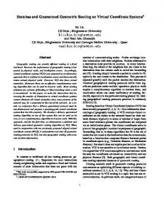
This section describes DiPUMP, a proposal of a radio network layer routing protocol for the underlying transport network of a NoF. To the best of our knowledge, DiPUMP is the first proposal on implementable distributed dynamic backpressure routing protocols for NoFs. The first subsection explains the main characteristics of DiPUMP. The second subsection summarizes how the routing decisions are taken hop-by-hop based on backpressure theory. Finally, the third subsection describes how the queue backlogs are dynamically calculated by means of exploiting geographic information and data queue lengths. A. Main Idea The DiPUMP protocol mechanism is both stateless and distributed. It is stateless in the sense that it requires no previous route computation prior to sending a packet. Furthermore, since there are no stateful routes to maintain in the network, there is no need for extra processing to handle them. As a result, apart from the usual HELLO messages exchange, the protocol does not add any messaging control overhead. It is also distributed, as no centralized entity is required for its implementation. Thus, it can be implemented in an all-wireless NoF with low control overhead. The main idea behind DiPUMP is the distribution of resource consumption throughout the network whenever it is required. This happens as the network load increases. This concept can be illustrated with the use of heat maps, like the one in Figure 3. The circles represent a grid of HeNBs in an all-wireless NoF, where each circle is a HeNB. The colour in each HeNB represents the number of data packets transmitted. The heat map in Figure 3 illustrates how a flow sent by the HeNB in the bottom left corner of the NoF is transmitted to the LFGW in the top right corner of the NoF. As shown in Figure 3, DiPUMP distributes resource consumption throughout the NoF, as most nodes in the local network contribute to forwarding data packets to the destination.
by their queue length Qj(t,d), where Ni is the set of neighbours of node i. Assume that, at an instant t,, node i forwards a data packet to destination d. Thus, the next hop NHi(t,d) of node i at instant t to destination d is selected among all j∈Ni as follows. Given �� ��, �� = � ��, �� − Q ୨ �t, ��, the next hop NHi(t,d) is chosen as
arg maxj∈N ቄ��݆݅ (�, �)ቅ � ቀ��݆݅ (�, �)ቁ ≥ 0 i ��݅ ሺ�, �ሻ = ቐ ,
� ቀ��݆݅ (�, �)ቁ < 0
Where DQij(t,d) is the queue backlog difference between the queue length of node and the queue length of node at instant t for destination d. This means that the HeNB chosen as next hop is the one with the minimum queue length among all j∈Ni. In case all neighbours have a higher queue length, the data packet is not forwarded. Therefore, it neither causes contention nor interference in the network, and congestion is not worsened at neighbouring queues.
C. Queue Backlog Calculation Let Qi(t,d) be the queue backlog in HeNB i at instant t intended to reach destination d. HeNB i calculates Qi(t,d) as the sum of the physical queue length PQi(t) and the virtual queue length VQi(d), i.e., � ��, �� = � ��� + �� ���, where the Physical Queue Length PQi(t) is the number of data packets queued for transmission in HeNB i at instant t. Therefore, PQi indicates how congested the transmission queues are. The routing protocol maintains a queue for the storage of data packets that are waiting to be transmitted whenever there is a transmission opportunity. At any given instant, this value is unique per HeNB no matter what the destination is. Furthermore, it can be calculated at each HeNB by using local information. The physical queue length of the HeNBs is periodically exchanged between neighbours by means of HELLO messages. On the other hand, the Virtual Queue Length VQi(d) indicates the length of the virtual queue, which, in fact, is not a queue storing real packets, but an auxiliary value needed for the correct generation of the queue backlog gradient towards the intended destination. VQi(d) is calculated as a function of the distance D(i,d) from HeNB i to destination d, i.e., ��݅ ሺ�ሻ = �(�( , �)).
Figure 3
Heat map of DiPUMP in an All-Wireless NoF
B. Local Decision Based on Queue Backlogs The DiPUMP protocol is based on backpressure theory. DiPUMP guarantees that if the offered load is within the stability region (i.e., the network is able to serve the set of offered loads) the queue backlog in the nodes will be kept finite. In DiPUMP, a HeNB/node i adapts its routing decisions to certain conditions of its neighbours j∈Ni, which are represented
Therefore, as the distance from node i to d increases, VQi(d) also increases. Then, a default decreasing gradient of virtual queue backlogs towards the destination is constructed, which is independent of the physical queue length of the nodes. By applying backpressure, this default gradient guarantees the trend to direct data packets towards destination d. 1) Virtual Queue Length Maintenance In this paper, we advocate for using geographic information for calculating the Virtual Queue Length. We also detail the specific algorithm adopted to calculate the Virtual Queue Length for each packet traversing a HeNB in the NoF. a) Exploiting Geographic Information With regards to the Virtual Queue Length VQi(d), a different value is required for each potential destination d in the NoF. As a consequence, in a naïve approach, a list of VQi(d)
would be required to maintain a Virtual Queue Length value for each possible destination in the network. This, in turn, would require maintaining state information at each HeNB that scales as O(N), where N is the number of potential destinations in the NoF. To solve this scalability problem we propose to exploit geographic coordinates for the dynamic Virtual Queue Length calculation at each node. In order to do so, we assume that each HeNB knows its geographic position. Furthermore, we assume that the geographic coordinates of the destination are carried in the header. Therefore, each node uses this information to dynamically calculate the Virtual Queue Length on-the-fly and on a per-packet basis for each data packet traversing a node heading to any destination d. Notice that this calculation is strictly local, as it only uses information contained in the data packet and information in the local neighbour table. The specific algorithm for the on-the-fly VQi(d) calculation is presented below. Assuming that each HeNB in the NoF knows its geographic position does not pose a significant constraint, as there are already commercial HeNBs with built-in GPS chipsets available in the market. A virtual coordinate system or other localization schemes can be configured in the NoF should GPS coverage not be available (e.g., indoors). However, this issue is beyond the scope of this paper. b) Virtual Queue Length Calculation using Euclidean Distance Let pd(t) be the packet processed at a HeNB i at instant t intended to reach destination d. Each packet contains the geographic coordinates of the destination. In addition, every HeNB i must maintain a neighbour table storing the geographic coordinates of its 1-hop neighbours, j∈Ni, which is filled in by exchanging HELLO messages. For each HeNB neighbour j∈Ni, we define ed(j,d) as the Euclidian distance between the neighbour j and destination d. Additionally, let edmax, be the maximum Euclidean distance between any pair of HeNBs in the geographic region defined by the NoF. VQi(d) is calculated as ed(j,d) normalized to the maximum physical queue length PQmax divided by the path diversity factor (PD). PD determines the importance of VQi(d) with respect to PQi(t). In other words, as PD increases, the resources (i.e., the number of HeNBs) involved in the routing of a data flow also increases. Then, for instance, if PD=1, the Physical Queue Length and Virtual Queue Length have the same weight in the calculations carried out to make the packet reach the destination. In brief, the Virtual Queue Length for each HeNB j∈Ni is calculated as follows: ��݅ ሺ�ሻ = �݉ܽ∗ ݔ
݁݀ሺ , �ሻ
��݉ܽ� ∗ ݔ
,
where PQmax is the maximum length of the transmission queue. Therefore, no state is required at the HeNBs to maintain the Virtual Queue Length for each potential destination, as for each packet a new Virtual Queue Length is calculated by using neighbour coordinates and destination coordinates carried in the packet. In this way, the mechanism is designed to scale. IV.
IMPLICATIONS IN THE 3GPP ARCHITECTURE
The concept of an all-wireless NoF, along with the routing scheme described in this paper, has implications in the 3GPP architecture. However, these implications are local to the NoF and, therefore, totally transparent to the EPC. The following sections describe in detail each one of these implications.
A. Local Network of Femtocells Gateway As described in section II.B, LFGWs are mandatory network elements in the all-wireless NoF architecture. LFGWs implement a logical function called Proxy S-GW (P-SGW) that performs S1-U bearer termination and mapping between the NoF and the EPC, as well as user-plane data routing from/to the NoF and the EPC. In a NoF, one or multiple LFGWs are distributed throughout the local network. Given the nature of the routing protocol, packets may opportunistically traverse a LFGW different from the one that terminates the S1 bearer originated at the HeNB. In such situations, the P-SGW function in the source LFGW (i.e., the first LFGW reached by the packet) extracts the IP packet from the geographic packet no matter what the bearer endpoint is and forwards it to the destination LFGW (i.e., the one terminating the bearer) by means of traditional IP routing protocols running over the existing wired/wireless backbone amongst LFGWs. Once the packet has reached the intended LFGW, it is routed into the corresponding S1 bearer between the LFGW and the S-GW in the EPC. B. Local Location Management Scheme User location schemes in 3GPP networks rely on mobile subscriber identifiers, such as the Serving Temporary Mobile Subscriber Identity (S-TMSI). Since DiPUMP assumes that a HeNB can obtain the geographic coordinates of the intended destination within the local network, a Local Location Management scheme is needed in order to map a given 3GPP mobile subscriber identifier to the geographic coordinates of the HeNB where the subscriber’s UE is currently camped on. As LLM schemes are tightly coupled to 3GPP control-plane procedures, such as Paging or Tracking Area Update (TAU), its detailed description is beyond the scope of this paper. C. Local Traffic Data Offloading in the NoF As the concept of NoF has not been standardized in 3GPP Technical Specifications yet, there is no 3GPP mechanism that allows HeNBs to establish S1 bearers directly between them (i.e., without having to traverse an S-GW or a P-SGW) [3]. In our scenario, IP packets are routed over the NoF in a completely transparent way to existing 3GPP control- and userplane procedures. In order to solve the local routing issue, HeNBs in the NoF may implement LIPA mechanisms that are able to identify IP packets addressed to local UEs. Once detected, these packets are handed over to an underlay transport network that performs the routing procedures described above. This underlay network is built by inserting a new protocol layer between legacy IP and MAC layers in the HeNB protocol stack, which keeps working in the same way, as standard interfaces are respected. V.
EVALUATION
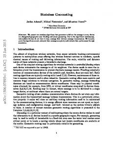
This subsection compares the DiPUMP protocol explained in section III with AODV-ST. The goal is to evaluate which protocol makes a better use of the NoF to transport radio network layer traffic. The first subsection summarizes the evaluation methodology. The second subsection analyses the results obtained in the simulation case under evaluation. A. Evaluation Methodology The experiments presented in this paper have been carried out with the NS-3 simulator [6]. HeNBs are placed in a 6x6 grid topology that represents a fully-connected dense NoF. The coordinates are assigned such that the Euclidean distance between two neighbours is 40 meters. Each HeNB is equipped with an 802.11a wireless card configured at a fixed rate of
F30 (200,0)
F31 (200,40)
F32 (200,80)
F33 (200,120)
F34 (200,160)
LFGW (200,200)
F24 (160,0)
F25 (160,40)
F26 (160,80)
F27 (160,120)
F28 (160,160)
F29 (160,200)
F18 (120,0)
F19 (120,40)
F20 (120,80)
F21 (120,120)
F22 (120,160)
F23 (120,200)
F12 (80,0)
F13 (80,40)
F14 (80,80)
F15 (80,120)
F16 (80,160)
F17 (80,200)
F6 (40,0)
F7 (40,40)
F8 (40,80)
F9 (40,120)
F10 (40,160)
F11 (40,200)
F0 (0,0)
F1 (0,40)
F2 (0,80)
F3 (0,120)
F4 (0,160)
F5 (0,200)
Figure 4
the input rate and so does the aggregate throughput at the LFGW. However, in AODV-ST, paths are predetermined. Consequently, the total number of HeNBs involved in the routing of packets is fixed, no matter the input rate. As a result, AODV-ST yields similar values in terms of aggregate throughput for different input rates once a certain threshold is reached (6 flows in Figure 5). LFGW Agg. Throughput(Mbps)
54Mbps. All 802.11a wireless cards in HeNBs are assigned to the same channel. There is a single LFGW at geographic position (200,200) (Figure 4). With regards to the configuration parameters of the routing protocol, the PD factor is set to 1 and HELLO messages are exchanged every 0.05 seconds.
Figure 5
B. Evaluation Results As shown in Figure 5, on average, DiPUMP outperforms AODV-ST in terms of aggregate throughput at the LFGW. On average, the number of HeNBs contributing to the transport of data flows in AODV-ST is lower than in DiPUMP. As a result, queue lengths of HeNBs transporting user-plane data flows in AODV-ST increase faster than in DiPUMP. This results into dropped packets due to excessive queue lengths in HeNBs. In contrast, DiPUMP is able to handle more packets in the NoF. On average, DiPUMP is able to transfer up to a 30% more packets to the LFGW than AODV-ST. DiPUMP also outperforms AODV-ST in terms of aggregate throughput fairness at the LFGW between HeNBs. Specifically, AODV-ST experiences higher variability in terms of aggregate throughput. In AODV-ST, depending on the position of the randomly-chosen HeNB sources, routing paths obtained by AODV-ST have a variable amount of HeNBs in common. Consequently, for each replication, the total number of HeNBs contributing to the routing of all flows is variable, and so is the aggregate throughput. In contrast, in DiPUMP, given an input rate, the number of HeNBs and its associated data packet distribution involved in the routing of flows does not vary substantially disregarding the exact position of source HeNBs in the NoF. Additionally, DiPUMP is able to dynamically increase the number of HeNBs contributing to the routing of data flows on a per-packet basis, whenever unmanageable input rates (i.e., excessive queue lengths) are detected. Consequently, the number of HeNBs involved in the path routing increases with
6
8
10 12
Number of Flows
Aggregate Throughput at the LFGW
VI.
The All-Wireless NoF Under Evaluation
The communication pattern considered in this paper consists of unidirectional UDP constant bit rate (CBR) flows of 2Mbps as user-plane traffic directed to the LFGW from any HeNB in the NoF (i.e., HeNBs with identifiers between 0 and 34). The packet size of the payload at the underlying IP layer is 1440 bytes. The evaluation consists of 40 experiments. Each experiment gathers data during 60 seconds and is repeated 6 times, which corresponds to 2, 4, 6, 8, 10, and 12 different random source HeNBs. Therefore, 240 simulations for each routing protocol have been generated, for a total of 480 simulations. Boxplots in Figure 5 represent the throughput variability in function of the HeNBs generating the communication flow.
20 AODV-ST 18 DiPUMP 16 14 12 10 8 6 4 0 2 4
CONCLUSIONS
In this paper we have evaluated the adequacy of DiPUMP as a distributed and stateless routing strategy for an all-wireless NoF. From the 3GPP architectural point of view, we have identified three main implications of the concept of NoF and DiPUMP as its underlying routing, namely the introduction of the LFGW, the need of an LLM mechanism, and the possibility of offloading local control- and user-plane traffic from the EPC to the NoF. Nevertheless, the deployment of NoFs has been conceived so that it does not require any modification to existing 3GPP procedures. Furthermore, performance evaluation results show that DiPUMP seems to be a more appropriate candidate than state-of-the-art routing (i.e., AODVST) one may use in this scenario. Specifically, DiPUMP outperforms AODV-ST in terms of aggregate throughput at the LFGWs mainly due to its better distribution of resource consumption throughout the network. More specifically, simulation results show that DiPUMP is, on average, able to attain LFGW aggregate throughput values 30% higher than AODV-ST. The impact of DiPUMP on jitter and packet reordering is still under evaluation and has been left for further study. ACKNOWLEDGMENTS This work has been partially supported by the Generalitat de Catalunya under grant 2009-SGR-940, the Spanish Ministry of Science and Innovation under grant TEC2008-06826, and performed in the framework of the ICT project ICT-4-248523 BeFEMTO, which is partly funded by the European Union. The authors would like to acknowledge the contributions of their colleagues from the BeFEMTO consortium. REFERENCES [1]
[2] [3]
[4]
[5]
[6]
3GPP TS 23.401: “General Packet Radio Service (GPRS) enhancements for Evolved Universal Terrestrial Radio Access Network (E-UTRAN) access”. 3GPP TS 23.829: “Local IP Access and Selected Traffic Offload”. 3GPP TS 36.300: “Evolved Universal Terrestrial Radio Access (EUTRA) and Evolved Universal Terrestrial Radio Access (E-UTRAN); Overall Description”. L. Tassiulas and A. Ephremides, “Stability properties of constrained queueing systems and scheduling for maximum throughput in multihop radio networks”, IEEE Transactions on Automatic Control, 1992. K. N. Ramachandran, M. Buddhikot, G. Chandranmenon, S. Miller, E. Belding-Royer, and K. Almeroth, "On the Design and Implementation of Infrastructure Mesh Networks", IEEE WiMESH, September 2005. The NS-3 network simulator, http:/www.nsam.org.