On Systematic Design of Globally Consistent Executable Assertions in Embedded Software∗ Arshad Jhumka
Martin Hiller
Vilgot Claesson
Neeraj Suri
Dept of Computer Engg Chalmers Univ. of Tech. Goteborg, Sweden ¨
Dept of Computer Engg Chalmers Univ. of Tech. Goteborg, Sweden ¨
Dept of Computer Engg Chalmers Univ. of Tech. Goteborg, Sweden ¨
Dept of Computer Engg Chalmers Univ. of Tech. Goteborg, Sweden ¨
[email protected] [email protected] [email protected] [email protected] ABSTRACT
1.
Over the design of software (SW) used in provisioning of dependable services, Executable Assertions (EAs) are seeing increasing usage in aiding detection of data errors. Given the requirements for provision of service despite faults, early detection of system states that can potentially lead to system failure is valuable. We address the issue of ascertaining whether localized EAs in individual modules add up complementarily to implement a global EA/property. We first show that detection of globally compliant EAs is NP-complete. Thus, we develop a two-pass approach for our objective. In the first pass, we introduce the consistency property of EAs and use it to ascertain global conformity across all EAs. The second pass, analogous to predicate transformers, generates globally consistent EAs when any inconsistency is flagged in the first pass. We show the applicability of our approach on a real embedded system. Initial results obtained show that our framework is able to detect inherent vulnerabilities (due to placement of mismatched EAs) that were previously undetected. Our intent is automation of this approach, which can be incorporated in a compiler.
Software (SW) is increasingly defining both the functionality and dependability attributes of embedded systems. Their development tend at integrating an assortment of SW functions, of varying requirements, onto shared hardware resources [18]. Given this integrated development, an error in one SW function may adversely influence other SW functions. In our previous work [10, 19], we developed a framework for quantifying error propagation between SW functions. Given that error propagation needs to be minimized, detectors and correctors [2] are incorporated in individual SW functions to constrain error propagation, ensuring correct delivery of service (temporal and functional). Thus, when designing the underlying SW to provide for desired functionality, error handling mechanisms such as Executable Assertions (EAs) [7, 8, 17] are incorporated to detect (and correct) erroneous signals and states that can potentially lead to failures. For many embedded applications, specifications only provide constraints on input and output signals and EAs designed to monitor these signals exhibit high detection coverages [8]. However, such EAs may not have high detection coverage for erroneous system states since, in distributed SW, the state is spread over different components. Thus to detect an erroneous state entails design of predicates that encapsulate the global state of the system, and EAs designed directly from signal specifications tend to have limited effectiveness 1 .
Categories and Subject Descriptors D.1.2 [Programming Techniques]: Automatic Programming—Program Modification,Program Transformation; D.2.4 [Software Engineering]: Software/Program Verification— Reliability; F.3.1 [Theory of Computation]: Logics and Meanings of Programs—Assertions,Pre- and post-conditions
General Terms Executable Assertions, embedded systems, semantics, abstract interpretation, application level fault tolerance ∗Supported in part by TFR grant and Saab endowment
Permission to make digital or hard copies of all or part of this work for personal or classroom use is granted without fee provided that copies are not made or distributed for profit or commercial advantage and that copies bear this notice and the full citation on the first page. To copy otherwise, to republish, to post on servers or to redistribute to lists, requires prior specific permission and/or a fee. LCTES’02–SCOPES’02, June 19-21, 2002, Berlin, Germany. Copyright 2002 ACM 1-58113-527-0/02/0006 ...$5.00.
1.1
INTRODUCTION
Illustrating Example Scenarios in EA Design
As a number of EAs are discretely specified and placed within the SW, these EAs need to detect any system state that will lead to violation of the problem specification [1], more specifically the safety specification of the system. The safety specification identifies a set of “bad” finite computation prefixes that should not appear in any program computation. Thus, we require the localized EAs to comply with the safety specification of the system, as specified by a global property2 (global EA), i.e., ascertaining that localized EAs are globally consistent3 . To comply with the safety specification, localized EAs are usually designed defensively, i.e., 1 High detection latency, low detection coverage for erroneous states, high rate of false alarms 2 We assume that the global property of the system is the same as the EAs monitoring the output signal(s) 3 We formally define the term consistency later in Section 1.1, Definition 1.
they filter out many non-erroneous states to ensure safety compliance, giving rise to false alarms, thus reducing the efficiency of the system. To better illustrate the concept of consistency, we present two examples, prior to providing its definition. Consider the following pseudo code segments with EA1 and EA2 depicting EAs in the code: Function 1 Function MultiplyBy5(int param) int val; ASSERT(param > 0); EA 1 val := param * 5; ASSERT(val > 25); EA 2 return(val); End Function
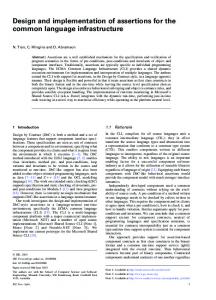
In Function 1, EA2 (val > 25 where val = param * 5) is the global EA and EA1 (param > 0) is a localized EA. EA1 and EA2 are not globally consistent since, for (0 < param ≤ 5) which are not flagged by EA1 , these values result in (val < 25), thus violating the safety specification of the global property. The resulting problem is that detection latency is increased, leading to possible corruption of system state. Overall, if the code linking these two EAs, i.e., val := param * 5, is denoted by F , then F (EA1 ) = EA2 , i.e., the code transforms EA1 into EA2 . This example scenario is depicted in Fig.1(b), which is an example of partial consistency. Consistency between two EAs can be classified into three categories, namely (i) consistent (ii) partially consistent, and (iii) inconsistent. If, graphically, we depict an EA as a pipe, consistent EAs are analogous to well-aligned pipes (Fig 1(e)) and inconsistent EAs to completely misaligned pipes (Fig 1(d)). Partial consistency is analogous to partially misaligned pipes (Fig. 1(a)–Fig. 1(c)). A set of EAs is globally consistent if all EAs are consistent with each other and they all together implement a global property. At this point, we provide a definition of consistency. Partially Consistent EAs
Defensive Programming EA1
EA2
(a) This miss will give rise to errors
Coarse Filter Before Fine EA1
EA2
(b)
Inconsistent EA Consistent EA
Partially Overlapping EAs EA1
EA2
EA2 EA1
EA 1
EA 2
All data will get rejected at this point.
(c)
Possible error propagation due to these misses.
(d)
Incompatible EAs
(e) The EAs provide complementary coverage.
Note that EA1 and EA 2 are related to each other through the code between them.
Figure 1: Examples of Consistent and Inconsistent EAs An EA (EAi ) defines a set of values, S(EAi ), that a given variable (Vi ) can take. Two EAs placed in a given SW system are linked to each other via code implementing a given function Fm . Definition 1. EA1 and EA2 are said to be consistent with each other iff Fm (S(EA1 )) = S(EA2 ). They are inconsistent iff Fm (S(EA1 )) ∩ S(EA2 ) = {}. They are
partially consistent iff they are neither consistent nor inconsistent.
1.2
Overall Contribution
Overall, having partially consistent and inconsistent EAs results in ineffective error handling in SW. This therefore calls for new methodologies for specifying and designing globally consistent EAs. We show in Section 4 that the detection of global consistency of EAs is intractable. Thus, we develop a two-pass approach, analogous to a two-pass compilation approach, to tackle this problem. Our approach is focused at the compiler level to allow for automation of the process. • Using abstract interpretation [4], we systematically verify the localized EAs for global consistency. We also provide a semantics-based framework for specifying and reasoning about EAs. • In the event of having EA inconsistencies in the first pass, the second pass systematically generates EAs that are globally consistent, analogous to the concept of predicate transformers [5]. Paper Organization The overall paper is organized as follows: Section 2 presents our chosen system and fault model used in the paper. Section 3 presents related work. Section 4 presents a proof of intractability of detecting global consistency of EAs, and then present our contribution. In Section 5, we present a brief introduction of abstract interpretation. In Section 6, we present our developed framework for specifying EAs, along with its formal semantics. Issues of EA consistency verification are also presented in this section. Section 7 presents the algorithm to generate globally consistent EAs and, in Section 8, we present an example to show the usefulness of our work and we briefly discuss the results obtained. Section 9 discusses the applicability, relevance and limitations of our framework. Section 10 briefly discusses our overall contribution and presents ongoing work.
2.
SYSTEM, PROGRAM, AND FAULT MODELS
The models used in the paper are: System Model We focus on embedded systems though the methodology can be applied to multiple SW/application modules on a uniprocessor as well as distributed systems. In embedded systems, the emphasis is on data values (signals). Program Model Our program model is one where EAs are included in SW, Fig. 2. Such EAs are derived from signal specifications, and are either preconditions or postconditions. Also, the applications under consideration can run on either a uniprocessor machine or across a distributed system. We also assume a white-box SW perspective, i.e., the internal structure of SW is known and modifiable. Fault Model As our focus is on embedded SW, the errors assumed in this paper are transient data errors in the input signals going into a given SW module, for example, due to bit-flips in memory areas or mutations prior to the signal input. Overall, we assume errors to enter the system from the environment (e.g., faulty sensor readings) and propagate during module interactions. When a transient error occurs, it means that a variable is holding erroneous data value.
Set of preconditions on the input signals
Set of input signals
Set of postconditions on the output signal
Program Module
Different value checks can be included in the body of the code here
Set of output signals
call/return statements
Program Module
Output signal defined with a global EA
Preconditions on signals passed to second module
Note:: The postconditions on the output signals (after the Call statement) and the preconditions on the input signals in the next module should be consistent. Local EAs within a module should be consistent as well.
Figure 2: A model of a typical module
2.1 Data Checking Using Executable Assertions: The Basic Approach An EA is an executable code fragment inserted in SW to assert the validity of the state of that SW, i.e., the EA checks whether the variables in the SW are holding erroneous values. Preconditions, postconditions and other range checks are all examples of EAs. Preconditions state the properties to be satisfied for proper execution. Violation of the preconditions is indicative of faulty inputs/initial state that may lead to erroneous execution. However, these are not efficient at checking the overall state of SW composed of several modules. Postconditions are code fragments that assert the validity of the final state. Postconditions state the properties that should exist after a successful execution of the module, while violation indicates that an error may have occurred during execution. Invariants are another type of EA that ensure that a given property is always satisfied during program execution and usually violation of preconditions and postconditions implies violation of invariants. Thus, in this paper, we will focus mainly on preconditions and postconditions.
3. RELATED WORK [8] shows the high detection coverage provided by EAs in detecting data errors in signals they monitor. The EAs used were derived from signal specification. [15] uses an approach based on both EAs and timed traces for on-line error detection and the EAs were designed from specification and were intended to detect errors in a given functional block only. [16] introduces an assertion processing tool that is used to address the concerns of ease-of-use and effectiveness. The tool is called APP, an Annotation PreProcessor for C programs developed in UNIX. It presented a classification for EAs that were most effective in detecting faults. However, it is left to the programmer to decide on EAs to be inserted in the code, potentially leading to inefficient EAs(see Section 4). An approach similar to [16] is described in [22]. [17] augmented PASCAL and FORTRAN compilers with assert instruction, and examples were provided to show its usage. [7] proposes an approach whereby the number of EAs can be reduced, through static analysis. They argue that intermodular analysis would allow a greater number of EAs to be reduced, but is however antithetical to the concept of separate compilation. So, they proposed an approach in which preconditions are declared in the interface definition of an
encapsulated object. The implementation consequences of this approach were then evaluated. On the other hand, [13] shows that EAs are difficult to design for distributed parallel environment. Thus, they proposed a set of basic metrics for certain classes of problems which results in assertions that are better suited for the parallel environment. [9] presented an approach analogous to the one that we present here, but relating to security properties. Their control-flow framework verifies whether local security checks inserted in individual modules provided the requisite protection as specified by a global security property. Thus, work on EAs has addressed the following issues: (i) ease of use [16, 17, 22], (ii) its efficiency [8], (iii) actual usage [15, 7]. One common denominator is that EA design is either random [12] or based on signal specification. As argued above, they have limited efficiency for detecting system state errors. Our work addresses the question of whether compiler support is possible in guiding design of globally consistent EAs. Presently, compiler support is only provided for ease of use [16, 17]. We envision our approach to complement that in [16]. To the best of our knowledge, little work has been done on the systematic design of EAs for SW. [11] presented algorithms (for various level of fault tolerance) for automating the design of fault tolerant programs, starting from fault intolerant programs. They adopted a state machine view of SW, whereby “faulty” transitions are identified and removed as necessary, depending on the fault tolerance level to be achieved. Our approach is analogous in that we endeavor at automating the generation of detectors [2], that can be incorporated in SW. Further, once these EAs have been incorporated in SW, Fault Injection [3, 14] experiments are performed to validate and evaluate the effectiveness of EAs and the usual metrics to evaluate their effectiveness are detection latency and detection coverage. While these metrics are useful, they do not however highlight vulnerabilities in the system (e.g., defensive programming). Thus, we need to develop a framework that can provide complementary EA information to be usable in detecting vulnerabilities across EAs and SW. Before presenting our approach, we discuss the tractability of detecting globally consistent EA’s.
4.
NP-COMPLETENESS OF GLOBAL PROPERTY CONSISTENCY
The program P consists of a set of modules Mi . Each module Mi has a set Vi of variables defined in it. A global property of a system is a boolean valued function B defined S over the variables in V = i Vi of the system. We define a set L = {L1 . . . LN } of localized EAs (preconditions or postconditions) defined over the set V of variables. We use the notation B(L) to indicate the value of predicate B in a system with L = {L1 . . . LN }. Global consistency detection of EAs (GLOB) is a decision problem. It takes the form of: Given: a program P , a global property B and a set of system variables V . Determine: if there exists a set L of localized EAs Li ’s defined over V such that L is globally consistent with B through P . Claim: GLOB is NP-complete Proof: First note that the problem is in NP. A verifier for the problem takes as inputs the program P , the set L of
localized EAs and the global property B and then verifies if the set L is consistent with B, i.e., satisfies B. This can be done in polynomial time. If this can be done in polynomial time, then detecting the global consistency of EAs belongs to the set NP. We show NP-completeness of a simplified consistency detection where all variables in V can take value “true” or “false”. There is only one Li incorporated in Mi . We reduce the satisfiability problem of a boolean expression to GLOB by constructing an appropriate set of localized EAs. The set is constructed as follows: Choose an Li ∈ L such that Li = “false” and include a new variable vj ∈ V such that Li is now “true”. It is easily verified that the predicate B is true for some set L if and only if the global property is satisfiable.
ceives input from the environment), the algorithm systematically derives new EAs consistent with the global EAs. We endeavor to tackle the problem of modifying the “weak links” (inconsistent EAs) in the SW. Section 7 presents the algorithm which helps in generating consistent EAs. The EAs we generate are preconditions, given our fault model (transient errors at the signal level), hence the need to ascertain their validity. However, our method easily scales to tackle the problem of transients occurring in internal state variables. Pictorially, our approach is as in Fig. 3. Precondition Module 1
1. Development of an approach to verify the set of EAs for global EA compliance 2. Systematic generation of EAs that are consistent with the global EAs For the first problem, we use the concept of abstract interpretation to perform this verification. Since the semantics for abstract interpretation are set-based, we present a settheoretic based semantics framework that allows EAs to be specified and reasoned about. Given the compatibility of semantics of both frameworks, verification of EA consistency in an abstract evaluation framework is facilitated. For the verification part, starting from preconditions (signal specifications), analogous to formal methods such as B and Z [21], annotations [6] are systematically generated. Since abstract interpretation works with abstract values rather than concrete values, annotations represent the abstract value generated for a particular variable. Section 5 provides more detail on abstract interpretation and annotations. Thus, at relevant locations in the code where localized EAs are placed, the range of values, as specified by the EA, of the monitored variable is compared with that defined by the annotations. Any mismatch is flagged, indicating inconsistencies in EAs. The first pass will be explained in more detail in Section 6. Whenever the compiler flags an inconsistency, the compiler helps the programmer in designing globally consistent EAs by identifying the relevant variables for their design. We present an algorithm that, given the global property, returns the necessary localized EAs to be placed in different modules. This step works in a way analogous to predicate transformers. Therefore, via backtracking, from the EAs defined on the output signals in the sink module those defined on the input signals in the source module (module that re-
Postcondition Precondition
Module 2
4.1 Specific Problems and Contributions Addressed Given the intractability of global consistency detection of EAs that explains the observation in [12] (i.e., that designing checks is a random and difficult process), our overall contribution is the definition of a framework that addresses this problem. We endeavor to identify the more critical variables that will allow detection of erroneous global state. Such action can be performed with compiler help. Thus, our approach is based on abstract interpretation. Specifically, we allow the compiler to guide the design of EAs such that they are consistent with the global EAs. Specifically, the objectives of this paper are:
EA
EA Postcondition
Set of global EAs
First sequential pass of the process where EAs are incrementally verified for consistency.
Second pass of the process where the algorithm systematically generates consistent EAs for different modules.
Precondition Module N
EA Postcondition
Each module may contain a set of preconditions, postconditions and other range checks
Figure 3: Two-pass approach for designing consistent EAs. At this point, we stress that this represents a first cut at trying to systematically design globally consistent EAs, with the help of the compiler, thus trying to improve on random design of EAs and checks for SW [12].
5.
PROGRAM ANALYSIS USING ABSTRACT INTERPRETATION: AN OVERVIEW
Compile time type verifications of high level language are usually incomplete. For example, explicit checks should be incorporated to avoid presence of null pointers etc. A static analysis of a program based on abstract interpretation consists of an abstract evaluation of the program, i.e., it is a “symbolic” interpretation of the program using abstract values rather than concrete (or execution) values [4]. An abstract value is a set of concrete values. Specifically, an abstract evaluation corresponds to a set of concrete evaluations where each concrete evaluation represents a possible fault-free execution. However, for each concrete semantic rule defined on a programming language, a corresponding abstract rule needs to be defined. For example, the “+” operator is defined on concrete values in a given high level language, however for abstract evaluation, the “+” operator needs to operate on range of values. In general, abstract interpretation provides a lot of run-time information without having to run the program on many input cases. An abstract evaluation of a program computes an abstract context at every program point. An abstract context is a set of pairs (v, a) that expresses that variable v has abstract value a at some program point p. The abstract value a then denotes the corresponding annotation on variable v at p. Abstract evaluation builds an initial context from initializa-
tion information provided in the program. At each program point, the abstract context changes. However, given that EAs are defined at certain program point to check for erroneous states, we modify the abstract context according to the value constraints defined by EAs. To achieve this, we need a framework to reason about EAs. In Section 6, we provide a formal framework for specifying EAs, with associated semantics that is compatible with abstract interpretation, i.e., a set-theoretic semantics. During abstract evaluation, when an EA (EAi ) monitoring variable vi is reached, the range of values it defines for vi is matched against its corresponding annotation at that point. Any mismatch results in the compiler to flag an inconsistency. Specifically, it means that EAi is not consistent with the signal EAs. We refer the interested reader to [4] for more details on abstract interpretation.
a variable/signal. Using the above framework, it can be represented as shown above, where V 0 denotes the previous value of V . This example expresses the fact that the value of V should be between a and b as well having its rate of change bounded. • (¬(a ≤ V ≤ b)) – This denotes that V does not belong to the set of values bounded by a from below and b from above. The semantics of the above framework is intuitive and is based on set theory and is presented below: Note that S() denotes the set defined by the EA specified. • S(C) = {x | C(x)} – This set will contain values that satisfy the constraint C, i.e., all values that fall within the range defined by C. From the example above, S(a ≤ V ≤ b) = {a...b}.
6. PASS 1: FORMAL DEFINITION OF EXECUTABLE ASSERTIONS AND ASSOCIATED FORMAL SEMANTICS
• S(A1 ∧ A2 ) = S(A1 ) ∩ S(A2 ) – When there is conjunction of EAs, the resulting set of this conjunction is an intersection of the individual sets defined by each EA.
At this point, we have shown the intractability of globally consistent EA generation. Thus, prior to generating globally consistent EAs, we first assess global consistency of EAs currently defined in SW. To perform consistency verification, in this section, we develop a framework for specifying and reasoning about EAs.
• S(A1 ∨ A2 ) = S(A1 ) ∪ S(A2 ) – The union of the sets defined by each EA will represent the set defined by the disjunction of the two EAs.
6.1 A Formalism for Expressing Executable Assertions We first provide basic definitions for signal EAs, which are constraints on signal values or on their derivatives [15]. Then, usual composition operators, such as ∨ (logical OR) or ∧ (logical AND), can be used to specify more complex EAs. We do not define all possible operators such as =⇒ (implies), since they can be expressed using the alreadydefined operators. An EA, in its simplest form, is a constraint (C) on a variable (signal). The framework for specifying EAs is presented below: A ::= C | (A ∧ A) | (A ∨ A) | ¬A The above representation means that a constraint C (a range of values) is an EA, a conjunction/disjunction of EAs is an EA, as will the negation of an EA. Some examples of EAs that can be expressed in the above framework are: • (a ≤ V ≤ b) – It defines a range of values that V can take, i.e., the minimum value V can take is a and the maximum b. • (a ≤ V ≤ b) ∧ (c ≤ V ≤ d) – It defines two sets of values that V can take, but V needs to simultaneously belong to each set. This represents a conjunction of EAs. • (a ≤ V ≤ b) ∨ (c ≤ V ≤ d) – It defines two sets of values that V can take, but V needs to belong to at least one of the set. This represents a disjunction of EAs. • (a ≤ V ≤ b) ∧ (c + V 0 ≤ V ≤ d + V 0) – In embedded systems, there is a need to represent rate of change of
• S(¬A) =U \ S(A) – This is the universal set less the set of values defined by the EA. The EAs above have a straight forward interpretation. Conjunction of EAs lead to a more constrained set of values whereas disjunction leads to a less constrained set. The reason for using a set theoretic semantics is two fold: (i) it corresponds well with the abstract values used in abstract interpretation and (ii) all set operators can be used for set manipulation.
6.2
Verification of Consistency of Executable Assertions
Having introduced a framework that allows specification of EAs, we now define relevant properties of EAs to be able to verify their consistency. Four scenarios exist, namely: • EA1 and EA2 (see Fig. 4) define sets of values that are related to each other through the implementation. • The set of values defined by the EA1 , when processed by the implementation, yields a proper subset of the one defined by EA2 • The set of values defined by the EA2 is a proper subset of the set defined by the EA1 , after being processed by the implementation. • EA1 and EA2 are incompatible, i.e., the sets of values defined by the EAs are uncorrelated through the implementation. In Fig. 4, F() represents the function implemented by the code between EA1 and EA2 . Note that when data is being passed from one module to the other (during return instructions, see Fig. 2), F() represents the identity function, i.e., EA1 is a postcondition and EA2 is a precondition and the data being passed is not acted upon during transmission. For each of the above, we present a definition of the corresponding property. Note that F() still denotes the code implementation linking EA1 and EA2 .
EA1 and EA2 may have various relationships through the implementation
EA1
Function F( )
EA2
Implementation of module
Figure 4: EAs are related to each other through the code implementation
puts of the module is obtained. Composing modules imply consistency of their precondition and postcondition. Thus, to achieve this, the precondition developed at this point is translated as postcondition for the preceding module. The same process is repeated until EAs are generated for each module. Thus, the algorithm is summarized as follows: • Inputs To the Algorithm Final-Output-EA (global EA), Sink-Module, ModuleInterconnections • Backtracking Within A Module Starting from the Final-Output-EA in Sink-Module, proceed backwards statement by statement, identifying the conditions necessary to compute the value of the output signal. Substitute the output signal by the conditions to obtain an EA for the input signals.
Property FC. EA1 is Fully Consistent with EA2 iff F(S(EA1 )) = S(EA2 ). For example, consider the case of a signal being • Propagation Part Using the new preconditions, genpassed from one module M1 to another module M2 . EA1 erate new EAs for different variables. (postcondition) in M1 should be fully consistent with EA2 • EAs Across Modules (precondition) in M2 so that they offer complementary covWhen the beginning of Sink-Module is reached, transerage. late the preconditions obtained into postconditions for Property MR. EA1 is More Restrictive than EA2 iff the other communicating module, whose identity is obF(S(EA1 )) ⊂ S(EA2 ). This happens when EA1 defines a tained using information from the Module-Interconnections. Re-execute the algorithm in the new module with these smaller set of values than EA2 (see Fig. 1(a)) Such a situapostconditions as input, Sink-Module updated to the tion can give rise to “false alarms”. new caller module, Module-Interconnections remainProperty LR. EA1 is Less Restrictive than EA2 iff S(EA2 ) ing the same. ⊂ F(S(EA1 )). This happens when EA1 defines a larger set of values than EA2 (see Fig. 1(b)). Such a situation can • Iterate until Source Module Reached Repeat until the source module is reached. give rise to EA1 having a lower detection coverage, or the detection latency can increase. The specific algorithm operations are as follows: Property I. EA1 is Incompatible with EA2 iff they do not satisfy any of the above properties. For example, supDerive_EA(, pose F(S(EA1 )) defines a set {0..10} and S(EA2 ) defines a , set {15..25}. These two sets are said to be Incompatible. ) In this section, we have presented the framework for spec{ ifying EAs and verifying their consistency. Prior to present1 while (NOT beginning of ) ing the usefulness of our framework, in the next section, we { will present an algorithm that systematically derives consis2 for (all variables V in ) 3 conditions(V) := tent EAs. Subsequently, we will provide a proof of correctdetermine_from_module(); ness for the algorithm. %Conditions for computing variable V %determined from module } 7. PASS 2: AN ALGORITHM TO GENER4 conditions():= ATE CONSISTENT EXECUTABLE ASget_all_conditions(); %All conditions for computing output signal SERTIONS In sections 6.1 and 6.2, we presented a framework that allows EA to be specified and verified for consistency to determine if they conform to a global EA. In the advent of the EA set being inconsistent, we have developed an algorithm that systematically generates consistent EAs. This algorithm can guide the system developer in designing the correct EAs with respect to a global EA.
7.1 Overview of the Algorithm Operations Overall, the algorithm works as follows: it first executes a backtracking phase. It starts with the global EA (defining the safety specification) and proceeds backwards to identify the conditions for computing the value of the output signal. For example, reusing function 1 from our previous example, the condition for computing the output val is param * 5. From the global EA val > 25, we substitute the condition for val, resulting in a new EA, 5 ∗ param > 25. The same process is repeated until an EA relating monitoring the in-
5 new_preconditions := output_EA[conditions(OutputSignal)/OutputSignal] %new preconditions obtained by substituting %output signal by the condition obtained 6 postcond_prev_module := new_preconditions; %preconditions translated as %postconditions in preceding module 7 preceding_module := get_preceding_module(module_name, module_interconnections); %gets the id of the other module %with which module_name is communicating 8 if (preceding_module == NIL) break; %source module reached 9 Derive_EA(postcond_prev_module, preceding_module, module_interconnections); }
Note that if there are multiple outputs (each associated with a global EA), then this algorithm needs to be executed for each output signal. The presented algorithm initially takes as input the global EA set that monitors the final output. It will then systematically derive the local EAs that are in conformance with the global EA.
7.3
At this point, we address some potential limitations of the above algorithm, more specifically regarding termination in presence of loop structures in or among modules. We address each case individually. 1. For the first case, i.e., if there is a loop in a module, during the first pass of the approach, it is possible to provide both a lower and upper bound on the number of iterations of the given loop, using techniques such as instrumented semantics [6]. This information can be reused to trace through the loop a finite number of times during the second pass. Thus, the intractability problem presented by the looping structure is alleviated. However, if an upper bound cannot be obtained, a timeout value can be used to halt the algorithm, similar to the technique used in [6], thereby generating an error message for the programmer. Another method may be to have user assistance in generating the EAs rather than having a fully automatic generation of EAs.
7.2 Proof of Correctness of the Algorithm Having presented the algorithm, we now present an informal proof of correctness, i.e., that the algorithm will return EAs that are consistent with each other. We make use of three lemmas for the proof. As inputs to the algorithm, we have the global EA monitoring the output signals. We also know the input signals to the modules. States of programs can only be changed through assignment statements, however, the changes depend on the state of the program at that point, i.e., there can be multiple data paths linking the input signals and the output signals, and the data path taken is determined by the state at that time. In the proof, we denote the output signal as OutputSignal and FM denotes the function implemented by a given module M . Lemma 1 Along any data path taken, there exists at least one assignment of the form OutputSignal := F (...) for the output signal to have updated data value. Proof of Lemma 1: If there is no assignment where OutputSignal is the target destination, then it will only contain its initialization data value or a constant value. Hence, for it to have updated data, the assignment F (...) should be a function of some other variables, i.e., F () should hold the conditions (variables) used to compute the OutputSignal. Lemma 2 The values held by the variables determining the value of OutputSignal should either be input signal data values or result from applying a function on the input signals. Proof of Lemma 2 If the variables which determine the data value of OutputSignal does not hold input signal data values (or values that depend on input signal data values), it implies that OutputSignal does not depend on the input signals. This is inconsistent with having input signals going into that module. Using the two lemmas, we can deduce that OutputSignal can be expressed as a function (FM ) of the input signals. Hence, in the EA monitoring OutputSignal, we can substitute OutputSignal by the function executing on the input signals. Thus, for a global EA of the form a < OutputSignal < b) we replace OutputSignal by FM (inputsignals), resulting in a < FM (inputsignals) < b). This expression can be simplified as appropriate. Thus, preconditions monitoring the input signals are obtained. From Lemma 1 and 2, we show that the algorithm does generate preconditions from output signals specification. Lemma 3 The preconditions are consistent with the global EA. Proof of Lemma 3 From the above, the precondition is as follows:a < FM (inputsignals) < b). Executing FM on the input signals will result in OutputSignal, hence a < OutputSignal < b), which is the global EA. Hence, the precondition and postcondition will be consistent. Lemmas 1, 2 and 3 constitute the overall proof of correctness of the algorithm.
Notes on the Algorithm
2. For the second case, i.e., having feedback loops among modules, strategies similar to the above can be used. 3. Another possible technique for tackling this problem is to use techniques for deriving weakest preconditions, since the second pass is analogous to predicate transformers. Techniques such as those used in [6] were used to derive worst case execution time (WCET) of SW, whereby dead paths are pruned so as to allow tight evaluation of WCET. Our framework can reuse all of the information generated during that phase, such that the consistency verification can be done with without much overhead. In the next section, we demonstrate the usefulness of our framework in a real embedded SW.
8.
AN EXAMPLE OF THE USEFULNESS OF THE FRAMEWORK
At this point, we have presented the framework for specifying EAs and verifying them for consistency. We also presented an algorithm that will systematically generate globally consistent EAs. In this section, we will present an example to show how our proposed algorithmic framework works. Our example is a real life aircraft arrestment system with embedded computer control. For reasons of space, we will initially focus ourselves on two communicating modules but, in later work, we will apply our framework to the rest of the system such that the whole system can later be tested for EA consistency.
8.1
Target System: An Example of an Embedded Control Software
The target system is an embedded control system [20] used in arresting aircraft on short runways. The software architecture of the target system is shown in Fig. 5. The software comprises six modules and a set of input/output signals to each module. The functionality of each module is summarized below. • CLOCK provides a clock, mscnt, with one millisecond resolution, while the ms-slot-nbr provides the module
scheduler with the current slot number for ”scheduling” purposes. The system is slot-based, with seven 1 ms slots in which one or more of the other modules are executed (except the CALC module). • DIST-S monitors the rotation sensor and provides a total count of the pulses, pulscnt, generated during the arrestment. Two outputs (stopped and slow-speed) indicates whether the aircraft has stopped and whether the speed is below a certain value, respectively. • CALC uses the signals mscnt, pulscnt, stopped and slow-speed to calculate a set point value for the SetValue output at different checkpoints along the runway. • PRES-S monitors the pressure sensor, measuring the current pressure on the pressure valve. This value is provided in IsValue. • V-REG uses the signals SetValue and IsValue to control OutValue, the output value to the pressure valve. The value of the OutValue signal is calculated by evaluating a function on the difference between the SetValue and the IsValue signals.
postconditions were obtained from the specification of the signals. We perform an EA consistency verification to demonstrate applicability of our framework. We assess the consistency between the preconditions defined on the input signals to V-REG module (IsValue and SetValue) and the postconditions on OutValue is V-REG. We note that if localized EA’s are not consistent, then they are not globally consistent as well.
8.2
V-REG Module 1. IsValue := Get-Is-Value(); 2. SetValue := Get-Set-Value(); Pre(SetValue); Pre(IsValue); 3. Error := SetValue - IsValue; 4. Error := F(Error); 5. Prop := G(Error); 6. Int := H(Error,Int); 7. OutValue := Prop + Int; Post(OutValue); 8. Return(OutValue);
• PRES-A uses the OutValue signal to set the pressure valve. ms−slot−nbr
mscnt CLOCK i
pulscnt
PACNT TIC1
DIST−S
TCNT
stopped SetValue
counter)
Pressure Sensor
CALC
slow−speed
( HW
PRES−A
TOC2 Pressure Valve
IsValue
ADC PRES−S
High Level Abstraction of the Modules
Before presenting our verification, we will present a highlevel description of the two modules. The pseudo-code presented below is for the V-REG module. It takes two signals (IsValue and SetValue) as inputs and calculate a value for the output signal (OutValue). F, G and H represent shorthand notation for the functions defined. We note that if two EAs are not consistent with each other, then the EA set is globally inconsistent.
V−REG
OutValue
Figure 5: Software Architecture of the Target System This particular example was chosen since it represents the kind of software for which our framework has been designed, i.e., control software. Since it has signals being sent from one module to another, EAs can be used to monitor the transmitted signals. The example that will be presented will focus on EA consistency between those defined in modules V-REG and PRES-A. The reason why these two modules were chosen is due to the fact that annotations are more easily derivable than if bigger modules were used. As future work, we are looking to automate the annotations generation process. Then, we will apply our framework to the current target system to assess its robustness through EA consistency. However, the example that we present has all the necessary features(e.g., has multiple inputs as any other modules) needed for discussion, and to show the applicability of our proposed approach. For our example, we used the target system of [8], where V-REG module had both preconditions and postconditions defined and PRES-A had preconditions defined on its inputs. Originally, the system from [20] did not have these preconditions defined. It was however enhanced in [8] to include the preconditions. Note that the preconditions and
8.3
Pass 1: Consistency Verification Using Annotations
This verification makes use of annotations. We first state the preconditions (from specification) on both input signals (IsValue and SetValue) and postcondtion on the output signal (OutValue). The preconditions defined in module V-REG are: • SetValue: (192 ≤ SetV alue ≤ 3200)∧(−160 ≤ SetV alue− SetV alue0 ≤ 800) • IsValue: (0 ≤ IsV alue ≤ 3200) ∧ (−192 ≤ IsV alue − IsV alue0 ≤ 500) Thus, we obtain: • SetValue: (a ≤ SetV alue ≤ b) a = max[192, −160 + SetV alue0], b = min[3200, 800 + SetV alue0] • IsValue: (c ≤ IsV alue ≤ d) c = max[0, −192 + SetV alue0], d = min[3200, 500 + SetV alue0] Annotations obtained by abstractly evaluating the code in V-REG are: (3+) a − d ≤ Error ≤ b − c (4+) a − d + E0 ≤ Error ≤ b − c + Error0 (5+) (a − d + E0)/4 ≤ P rop ≤ (b − c + Error0)/4 (6+) (a − d + E0)/8 + Int0 ≤ Int ≤ (b − c + Error0)/8 + Int0 (7+) 3(a − d + E0)/8 + Int0 ≤ OutV alue ≤ 3(b − c + Error0)/8 + Int0
(i+) means after line i in V-REG module above. The postcondition on OutValue is m1 ≤ OutV alue ≤ m2 where m1 = max[32, −192+OutV alue0] and m2 = min[3200, 500+ OutV alue0]. From item 7+ above and the postcondition on OutValue, an inconsistency is detected. More detailed calculation shows that the annotation 7+ above offers less constraint than the postcondition. Hence, the situation is as in Fig 6.
EA for SetValue or IsValue
EA for OutValue
just VCALC . Hence, following our earlier discussion, we argue that since the EA in CALC is made up of variables from different modules, it may detect a system state error more effectively. In fact, with this postcondition in module CALC, if there is an error in module PRES-S whereby signal IsValue has an erroneous value, this is detected by the postcondition due to the inclusion of the IsValue signal. It also means that, instead of using two EAs as was previously the case, only one EA can be used to protect both signals at the same time. We make two important observations here: 1. It can be observed that it would have been better to monitor the two input signals in V-REG by one EA (dynamic EA), rather than having individual EA monitoring each signal, as was the case in [8].
Figure 6: Consistency Between Preconditions and Postcondition in V-REG
2. From the verification, we can explain the observation in [8] where an error in IsValue was not detected by the EA monitoring it. This error however propagated to the output and was trapped by the EA monitoring OutValue in PRES-A. The EA in PRES-A had a higher detection coverage than the one monitoring IsValue, since it was more restrictive one (see Fig. 1(b)). This also gave rise to a higher error detection latency.
This discrepancy highlights two possible weaknesses in the system: 1. The implementation of module V-REG is incorrect, or 2. The EAs defined in modules V-REG and PRES-A are inconsistent, and hence will give rise to weaknesses in the system. Also, with current experimentally based metrics such as detection coverage, such weaknesses may not be detectable.
At this point, one assumption we have made is that the code in V-REG is correct. In fact, the inconsistency between EAs point to either EAs being badly designed (as above) or the code being incorrect.
8.4 Pass 2: The Algorithm at Work– Generation of Consistent EAs
9.
From the previous two sections, we found that the EAs were not globally consistent. So, the compiler would flag this inconsistency and execute the algorithm to obtain globally consistent EAs. The global property defined for this system is the same as that defined on the OutValue signal. The postcondition in V-REG on OutValue is ([-96 + OutV alue0 < OutV alue < 500 + OutV alue0]) ∧ (32 < OutV alue < 3200), denoted by P (OutV alue). Since the PRES-A module just converts the OutValue signal into TOC2, we consider the V-REG module as the sink module. Thus, executing the algorithm, we obtain the following for module V − REG: (7+) (m1 ≤ OutV alue ≤ m2 ) (6+) (m1 ≤ P rop + Int ≤ m2 ) (5+) (m1 ≤ 3E/4 + Int ≤ m2 ) (4+) (m1 ≤ 3(E + E0)/8 + Int ≤ m2 ) (3+) (8m1 − 3E0 − 8Int ≤ 3(SetV alue − IsV alue) ≤ 8m2 − 3E0 − 8Int)
APPLICABILITY OF THE FRAMEWORK
In this section, we provide insights on the applicability and relevance of our framework. 1. One important aspect of being able to assess the consistency of EAs is that it allows vulnerabilities in the SW to be detected. By vulnerabilities, we mean whether the EAs comply to the safety specification of the SW or whether the implementation is correct or not. Specifically, given two EAs, EA1 and EA2 , that are inconsistent with each other and assuming that EA2 is consistent with the global EA, then we can deduce that either EA1 is not correct (is not consistent with the global EA) or the implementation linking EA1 to EA2 is incorrect, i.e., EA1 is not transformed into EA2 . If the relation between the set of EAs is other than that defined by the implementation of module M , then this highlights potential implementation problems in the module. Also, information pertaining to the detection latency can also be obtained (see Fig. 1(b)). Thus, the EA consistency assessment process will highlight weaknesses in the SW design.
2. Another important aspect in designing reliable software is the ability to reuse formally verified SW modwhere m1 = max[32, −192+OutV alue0] and m2 = min[3200, 500+ ules. As mentioned in [2], a fault-tolerant system is OutV alue0] and [i+] means the EAs after line i. composed of a fault-intolerant system together with Starting the second iteration, we translate the precondia set of fault-tolerance components, namely detectors tion on the signals SetValue and IsValue as postcondition and correctors. We adopt this perspective and we in either module CALC or PRES-S. In our case, it will be argue that reuse may be facilitated through reuse of translated as postcondition is module CALC. Now, an EA fault-intolerant components, which can be composed in CALC makes use of variables from the set V rather from with the relevant fault-tolerance components. Given
that a particular module may be used in different applications deployed in environments subject to different kinds of faults, the fault-intolerant module needs to be composed with the appropriate fault-tolerance components to detect and recover from errors. This points to a need for a framework that can guide the system designer in developing the requisite fault-tolerance components. The algorithm addresses this problem by providing an automated way of generating EAs such that they comply with the overall safety specifications of the system. In such cases, such systems can be designed to be fail-safe. In [2], EAs are known as detectors. When composed with correctors, masking faulttolerant SW can be developed. 3. Also, having consistent EAs helps in performing incremental verification of the system. After verifying each module (both for functionality and for EA consistency), EA consistency verification across modules will ensure that the localized EAs are globally consistent. Also, in case of changing specifications, the verification needs only be local. If preconditions and postconditions of two communicating modules are consistent and are not changing, then the verification needs only ensure that the preconditions and postconditions within the changing module be verified for consistency.
10. DISCUSSION, LIMITATIONS AND FUTURE WORK In this paper, we have presented a framework for specifying EAs and verifying their consistency. To achieve this, we presented the relevant properties for verification purposes. In case the EA set is inconsistent, we have presented an algorithm that systematically generates a set of globally consistent EAs. We then presented a real-life example where we have verified that the localized EAs are inconsistent. We applied the algorithm to generate the globally consistent preconditions on the input signals, from which subsequent EAs for other variables can be derived. The problem discussed here is very relevant since many software systems are implemented defensively, lowering their efficiency. Our results have shown that this framework is able to detect subtle weaknesses in system design. This helps towards the development of reliable SW. Also, given that preconditions in one module is translated into postconditions in the preceding module, both need not be incorporated in the SW. Fault Injection experiment can be run to ascertain which one to incorporate. Our framework currently does not tackle the problem of timing constraints, which is important in embedded applications. As future work, we are looking at addressing timing constraints and its impact on EA design. This work represents a first cut at trying to verify global consistency of EAs. There are other possible future avenues to explore. We are looking to build a tool that can automate generation of annotations. We are looking to incorporate this framework into the C (gcc) compiler to generate globally consistent EAs. Our intent is to extend the compilation process to incorporate the first pass of our approach for consistency verification. EA’s could be inserted directly or indirectly using the APP tool [16]. The second pass is also implemented to return a set of globally consistent EA’s whenever a flag is raised due to inconsistencies. We also
plan to apply the framework to the rest of the target system to obtain a set of consistent EAs.
11.
REFERENCES
[1] B. Alpern, F.B. Schneider, “Defining Liveness”, Information Processing Letters, 21(4):181–185, 1985 [2] A. Arora, S. Kulkarni, “Detectors and Correctors: A Theory of Fault-Tolerance Components”, Proc ICDCS, pp 436–443, May 1998. [3] R. Chillarege, N. Bowen, “Understanding Large System Failures – A Fault Injection Experiment”, Proc. FTCS 19, pp. 356–363, 1989 [4] P. Cousot, R. Cousot, “Static Determination of Dynamic Properties of Programs”, Int. Symposium on Programming, 1976 [5] E.W. Dijkstra, “A Discipline of Programming”, Prentice Hall, 1976 [6] A. Ermedahl, J. Gustafsson, “Deriving Annotations For Tight Calculation of Execution Time”, Proc EuroPar’97, RT System Workshop [7] K.J. Gough, H. Klaeren, “Executable Assertions and Separate Compilation”, Proc Joint Modular Languages Conference, 1997. [8] M. Hiller, “Executable Assertions for Detecting Data Errors in Embedded Control Systems”, Proc. DSN 2000, pp. 24-33 [9] T. Jensen, D. LeMetayer, T. Thorn, “Verification of Control Flow Based Security Properties”, Proc. IEEE Symp.on Security and Privacy, pp. 89–103, 1999 [10] A. Jhumka, M. Hiller, N. Suri, “Assessing Inter-Modular Error Propagation in Distributed SW”, Proc. SRDS 2001, pp. 152–161 [11] S. Kulkarni, A. Arora, “Automating the Addition of Fault Tolerance”, Proc. Formal Techniques in Real Time and Fault Tolerant Systems, 2000 [12] N.G. Leveson, S.S. Cha, J.C. Knight, T.J. Shimeall, “The use of self checks and voting in software detection: An empirical study.”, IEEE Trans. on Soft. Eng., 16:432–443, 1990 [13] B.M. McMillin, L.M. Ni, “Executable Assertions Development for the Distributed Parallel Environment”, Proc. 12th COMPSAC, pp. 284–291, 1988 [14] D. Powell, E. Martins, J. Arlat, Y. Crouzet, “Estimators for Fault Tolerance Coverage Evaluation”, Proc FTCS-23, pp. 228–237, 1993 [15] C. Rabejac, J.P. Blanquart, J.P. Queille, “Executable Assertions and Timed Traces for On-Line Software Error Detection”, Proc. FTCS-26, pp. 138–147, 1996 [16] D.S. Rosenblum, “A Practical Approach to Programming with Assertions”, IEEE Trans on SE, Vol 21, No 1, pp. 19–31, January 1995. [17] S.H. Saib, “Executable Assertions - An Aid To Reliable Software”, Proc 11th Asilomar Conference Circuits Systems and Computers, pp. 277–281, 1978 [18] N. Suri, S. Ghosh, T. Marlowe, “A Framework for Dependability-driven Software Integration”, Proc. ICDCS’98 [19] N. Suri, A. Jhumka, M. Hiller, T. Marlowe, “A Software Integration Approach for Designing Dependable Embedded Systems”, Submitted to Trans. Parallel and Distributed Systems [20] US Air Force – 99, “Military Specification: Aircraft Arresting System BAK-12A/E32A; Portable, Rotary Friction”, MIL-A-38202C, Notice 1, US Department of Defence, September 2, 1986 [21] J. Woodcock, J. Davies, “Using Z: Specification, Refinement, and Proof”, Prentice Hall, 1996 [22] H. Yin, J.M. Bieman, “Improving SW Reliability With Assertion Insertion”, Proc ITC, pp. 831–839, 1994