the homography such that. mpT â ppT H. The following ... apT â ppT H, where H = [X, y] is a nonsingular ..... On the geometry and alge- bra of the point and line ...
On the Absolute Quadratic Complex and its Application to Autocalibration J. Ponce and K. McHenry Beckman Institute University of Illinois Urbana, IL 61801, USA
T. Papadopoulo and M. Teillaud INRIA Sophia-Antipolis 2004 Route des Lucioles, BP 93 06902 Sophia Antipolis, France
Abstract. This article introduces the absolute quadratic complex formed by all lines that intersect the absolute conic. If ω denotes the 3 × 3 symmetric matrix representing the image of that conic under the action of a camera with proT jection matrix P, it is shown that ω ≈ PΩP , where P is the 3×6 line projection matrix associated with P, and Ω is a 6 × 6 symmetric matrix of rank 3 representing the absolute quadratic complex. This simple relation between a camera’s intrinsic parameters, its projection matrix expressed in a projective coordinate frame, and the metric upgrade separating this frame from a metric one—as respectively captured by the matrices ω, P, and Ω—provides a new framework for autocalibration, particularly well suited to typical digital cameras with rectangular or square pixels since the skew and aspect ratio are decoupled from the other intrinsic parameters in ω.
1
B. Triggs INRIA Rhˆone-Alpes 665, Avenue de l’Europe 38330 Montbonnot, France
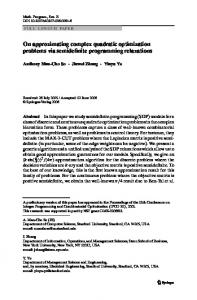
Figure 1: Left: Classical calibration devices include physical grid patterns and “virtual” objects such as the absolute conic and the (dual) absolute quadric formed by its tangent planes. The image lines tangent to the projection of the absolute conic form a dual conic, whose preimage is a subset of the absolute quadric. Right: The absolute quadratic complex (or AQC) is a new virtual calibration device formed by all straight lines intersecting the absolute conic. The preimage of the projection of the absolute conic (as opposed to its dual) is a subset of the absolute quadratic complex.
Introduction
Chasles’ absolute conic, an imaginary conic section invariant under similarities, plays a fundamental role in the study of metric properties of pinhole cameras: The problem of estimating the epipolar geometry of a pair of cameras from seven point correspondences was first posed by Chasles [4] and solved by Hesse [10]. As shown by Kruppa [12] and mentioned by Faugeras and Maybank [7], five point correspondences are sufficient for internally calibrated cameras, the absolute conic being used in that case to derive two tangency constraints that make up for the missing point correspondences. As shown by Maybank and Faugeras [13], the absolute conic (together with its image projection) also provides a “virtual” calibration device (Fig. 1) that can be used in autocalibration tasks [3, 8, 13], where both the intrinsic camera parameters and a metric scene reconstruction are computed from an initial, purely projective scene reconstruction obtained from multiple images, without the use of a physical calibration chart. In practice, it is often convenient to replace the absolute conic by Triggs’ absolute quadric [20], since it is easy to characterize the projection of this (dual) quadric surface in terms of the internal camera parameters, the projection matrix expressed in some projective frame, and a metric upgrade matrix that maps this coordinate system onto a metric one [14, 15, 20].
This article shows that similar constraints hold for the absolute quadratic complex formed by all lines intersecting the absolute conic. In particular, if ω denotes the 3 × 3 symmetric matrix representing the image of the absolute conic under the action of a camera with projection maT trix P, we will show in Sect. 3 that ω ≈ PΩP , where P is the 3 × 6 line projection matrix associated with P [5], and Ω is a 6 × 6 symmetric matrix of rank 3 representing the absolute quadratic complex. This simple relation between a camera’s intrinsic parameters, its projection matrix, and the corresponding metric upgrade—as respectively captured by the matrices ω, P, and Ω—provides a new framework for autocalibration, particularly well suited to typical digital cameras with rectangular or square pixels since the skew and aspect ratio are decoupled from the other intrinsic parameters in ω. In particular, we present a new derivation of the quasi-linear algorithm proposed by Ponce in [16] for cameras with square pixels but unknown and possibly varying focal length and principal point (see ˚ om [11] for iterative apBougnoux [3] and Heyden and Astr¨ proaches to the same problem), and a novel non-linear algorithm for cameras with square pixels and unknown but fixed focal length and principal point. A quantitative comparison between these two methods and the quasi-linear algorithms
proposed by Pollefeys et al. [14, 15] in the case of cameras with known principal point is also given.
Notation: We denote by P3 the projective completion of R3 considered as an affine space. Given some fixed coordinate frame for P3 , we identify points and planes with their homogeneous coordinate vectors in R4 . In this presentation, line Pl¨ucker coordinate vectors are sometimes written in the form δ = (u; v), where u and v are vectors in R3 , and the “;” symbol is used to indicate that the six coordinates are stacked onto each other to form a vector in R6 . We use f x, f p, and f δ to denote the coordinate vector of the point x, the plane p, and the line δ in a specific frame (f ). The symbol “≈” is used to express the fact that two vectors or two matrices are nonzero multiples of each other, e.g., x ≈ y, U ≈ V. Proofs: All propositions presented in the rest of this paper are stated without formal proofs. See [17] for these.
2
Line Geometry and Perspective Projection
This section briefly introduces elementary notions of line geometry, and discusses its relationship with the perspective projection process, as required for a good understanding of the rest of this article. This includes a characterization of coplanar lines and line bundles by trilinearities (Sect. 2.3), and the introduction of dual perspective projection (Sect. 2.1.4), topics that may be of interest on their own.
2.1 Elements of Line Geometry ¨ 2.1.1 Plucker Coordinates and the Join Operator This section introduces some elementary notions of line geometry. Let us first introduce the join operator “∨” that associates with the (homogeneous) coordinate vectors x = (x1 , x2 , x3 , x4 )T and y = (y1 , y2 , y3 , y4 )T of two points the Pl¨ucker coordinate vector of the line joining them: ⎡x y −x y ⎤ 4 1 1 4 ⎢ x 4 y2 − x 2 y4 ⎥ def ⎢ x4 y3 − x3 y4 ⎥ ⎥ x∨y = ⎢ ⎢ x2 y3 − x3 y2 ⎥. ⎦ ⎣ x 3 y1 − x 1 y3 x 1 y2 − x 2 y1
Pl¨ucker coordinates are homogeneous, and lines form a quadratic hypersurface L 4 of dimension 4 in the projective space P5 : Indeed, it follows immediately from the definition of the join that the Pl¨ucker coordinate vector δ = (u; v) of a line satisfies the quadratic Klein constraint u · v = 0. It is also possible to define an inner product in L 4 by the def formula (δ|η) = u · t + v · s, where δ = (u; v) and η = (s; t). A vector δ in R6 represents a line if and only if (δ|δ) = 0, and it can also be shown that a necessary and sufficient condition for two lines δ and η to be coplanar is that (δ|η) = 0. For reasons that will shortly become obvious, when δ = (u; v), it is convenient to define the vector δ ∗ = (v; u) so that (δ|η) = δ ∗ · η = δ · η ∗ . Remark 1 Consider two finite points with homogeneous coordinate vectors x = (x1 , x2 , x3 , 1)T and y = (y1 , y2 , y3 , 1)T in
some affine coordinate frame, and denote by x� and y � the corresponding non-homogeneous coordinate vectors. The Pl¨ucker coordinate vector of the line joining these two points is x∨y = (u; v), where u = y � − x� and v = (x� × y � ). In particular, the vector u is the affine direction of this line, defined up to scale.
2.1.2
Duality and the Meet Operator
The set of hyperplanes in P n forms a second projective space of dimension n, denoted by P n∗ and said to be dual to the original (primal) one. The points x in P n such that p · x = 0 for some fixed vector p �= 0 of R n+1 form a hyperplane p ∗ of Pn , whose dual is the point p of P n∗ . The dual of a point x in P n is the hyperplane x ∗ of Pn∗ formed by all hyperplanes p of P n that pass through that point—or equivalently, satisfy p · x = 0. We focus of course on the cases n = 2 and n = 3 in this presentation. The dual of a line in P3 is the one-dimensional pencil of planes passing through that line—that is, a line in P 3∗ . It is easy to show that the dual of the line δ is the line δ ∗ . The meet operator associates with two planes p and q the Pl¨ucker coordinate vector of the (primal) line p ∧ q where they intersect. This line of P3 is the dual of the join of the two planes in P 3∗ . Thus ⎡ ⎤ p2 q3 − p3 q2
⎢ p3 q1 − p1 q3 ⎥ ⎢ p1 q2 − p2 q1 ⎥ ∗ ⎥ p ∧ q = (p ∨ q) = ⎢ ⎢ p4 q1 − p1 q4 ⎥. ⎣ ⎦ p4 q2 − p2 q4 p4 q3 − p3 q4
2.1.3
Mixed Join and Meet Operators
The join operator can be extended to lines and points: Given a line δ = (u; v) and a point x not lying on δ, we define the join of δ and x as the plane spanned by the line and the point. Algebraically, it is given by δ ∨ x = [δ ∨ ]x, where � � [u× ] v def [δ ∨ ] = , T −v
0
and [u× ] is the 3 × 3 skew-symmetric matrix such that [u× ]w = u × w for any vector w in R 3 . A necessary and sufficient condition for x to lie on δ is that δ ∨ x = 0. The join of three points x, y, and z is the plane spanned by these def points, defined algebraically by x ∨ y ∨ z = (x ∨ y) ∨ z. The meet of a line δ = (u; v) and a plane p is the point where they intersect, which is given by δ ∧ p = [δ ∧ ]p, with [δ ∧ ] = [δ ∗∨ ]. A necessary and sufficient condition for δ to lie in the plane p is that δ ∧ p = 0. The meet of three planes p, q, and r is the the point where these planes intersect, dedef fined algebraically by p ∧ q ∧ r = (p ∧ q) ∧ r. def
2.1.4
Coplanar Lines and Line Bundles
Consider k lines with Pl¨ucker coordinate vectors δ i (i = 1, . . . , k) lying in the same plane. Obviously, each one of these vectors verifies the quadratic Klein constraint
(δ i |δ i ) = 0, and any two of them satisfy the bilinear constraint (δ i |δ j ) = 0 associated with a pair of coplanar lines. It is easy to show that any three of these vectors also satisfy four independent trilinear constraints (see Appendix), and that any four of them are linearly dependent. A line bundle is a set of lines passing through some point. Any two of these lines are coplanar, and their Pl¨ucker coordinate vectors also satisfy the quadratic and bilinear constraints (δ i |δ i ) = 0 and (δ i |δ j ) = 0. In addition, the bundle of lines passing through some point x is the dual of the set of lines lying in the dual plane x ∗ . Therefore, any three lines in the bundle satisfy a dual set of trilinear constraints, and any four of them are linearly dependent (see Appendix).
2.2
Definition 1 The line projection matrix associated with a 3 × 4 matrix P is the 3 × 6 matrix T
� ξ 1 = p2 ∧ p3 ≈ c ∨ x 1 , ξ 2 = p3 ∧ p1 ≈ c ∨ x 2 , ξ 3 = p1 ∧ p2 ≈ c ∨ x 3 .
ξ1 ξ T2 , where ξ T3
def
P =
The line projection matrix will play a fundamental role in the rest of this presentation. The following proposition states its fundamental properties (Fig. 3). See Faugeras et. al [5] for its proof.
r y’
Perspective Projection
c
A pinhole camera is defined by its optical center c and its image plane r. The corresponding perspective projection maps every point x distinct from c onto the point x � = (c ∨ x) ∧ r, i.e., the intersection of the ray ξ joining c to x with the plane r (Fig. 2).
p’
G’ x’
G [
[2
r x2 c
I� x3
I�
p3 x1
[1
I�
p2
x’
[3 [
x
Figure 2: Perspective projection. See text for details. In order to model this mapping analytically, we choose an arbitrary but fixed coordinate system for r and identify this plane with P 2 . Selecting a projective basis for r amounts to picking three non-collinear points x 1 , x2 , and x3 in that plane.1 Using the methodology of [5], it is then easy to show that the image of the point x is given in this coordinate system by T
x� ≈ Px,
where P =
p1 pT2 , pT3
and p1 = c∨x2 ∨x3 , p2 = c∨x3 ∨x1 , and p3 = c∨x1 ∨x2 are the projection planes of the camera. The projection of a straight line under the action of a pinhole camera with projection matrix P is characterized by the corresponding line projection matrix P, defined as follows in terms of the rows p Ti (i = 1, 2, 3) of P. 1 Here,
x
Figure 3: Line projection. See text for details.
as usual, we identify points and their coordinate vectors defined up to scale. The rest of our discussion assumes that the relative scales of the vectors xi are fixed. This can be done (for example) by using a fourth unit point to complete the specification of a projective frame for r.
Proposition 1 Consider a pinhole camera with projection matrix P. The corresponding line projection matrix P enjoys the following properties: (1) The projection of the line ∗ δ onto the image plane r is the line δ � ≈ P δ, where ∗ P is naturally defined as the 3 × 6 matrix with rows ξ ∗T i (i = 1, 2, 3). (2) The preimage of the image point x � is the T straight line ξ ≈ P x� . Remark 2 The vectors x� and δ � are written here in the bases (x1 , x2 , x3 ) and (φ1 , φ2 , φ3 ) for the image plane r and its dual, with φ1 = x2 ∨ x3 , φ2 = x3 ∨ x1 , and φ3 = x1 ∨ x2 (Fig. 2). T The columns ξ1 , ξ 2 , and ξ 3 of P are the coordinate vectors of three lines passing through c, and thus satisfy the quadratic, bilinear, and trilinear constraints associated with the corresponding T T T bundle. Note that writing that the lines P 1 x�1 , P 2 x�2 , and P 3 x�3 � � � associated with three images x1 , x2 , and x3 of the same point belong to the corresponding bundle, thus providing directly the four trilinear constraints associated with three views of that point, without the intermediate characterization of the trifocal tensor in terms of lines [9, 19, 21], or the algebraic manipulations traditionally used otherwise [6, 18].
2.3
Dual Perspective Projection
The perspective projection process can be decomposed into two mappings: x → ξ = c ∨ x, and ξ → x � = ξ ∧ r. Geometrically, the first mapping is the most important one, since the projective structure of the image is independent of the choice of r. In this view, perspective projection maps points onto lines (x → c ∨ x) rather than points, and lines onto planes (δ → c ∨ δ) rather than lines.
It is also useful to consider a dual version of this process: We first map any plane p different from r onto the line φ where these two planes intersect—that is, p → φ = r ∧ p, then map φ onto the plane p � spanned by c and φ—that is, φ → p� = φ ∨ c. Whereas (primal) perspective projection maps points onto points, dual perspective projection maps planes onto planes (Fig. 4).
x2
I� p’
x3
p
I
I�
p
≈ p X,
[3
where X = [ x1
φ1 φT2 , where φT3
x2
x3 ] ,
φ 1 = x2 ∨ x 3 ≈ r ∧ p 1 , φ 2 = x3 ∨ x 1 ≈ r ∧ p 2 , φ 3 = x1 ∨ x 2 ≈ r ∧ p 3 .
again that the relative scales of the vectors pi are fixed. a perspective projection matrix P, there exists a three† † such that PPq ≈ Id3 . parameter family of inverse projection matrices Pq They correspond to replacing r by an arbitrary plane q in our definition of † . the matrix X . In other words, X = Pr 2 Assuming 3 Given
p
x’
The following proposition states the main properties of the dual line projection matrix. It is a dual statement of Proposition 1, and its proof is omitted.
p2
Definition 2 The dual line projection matrix associated with a 4 × 3 matrix X = [x1 , x2 , x3 ] is the 3 × 6 matrix T
� def
G
[1
I�
and x1 = r ∧ p2 ∧ p3 , x2 = r ∧ p3 ∧ p1 , and x3 = r ∧ p1 ∧ p2 are points lying in the plane r. The matrix X is what Faugeras et al. [5] call an inverse projection matrix of the projection matrix P with rows p Ti .3 The (primal) perspective image of a line joining two points is the join of their images, and the preimage of a point is a line going through c. In the dual case, the line δ where two planes p and q intersect maps onto the meet δ � of their images p � and q � (see Fig. 5, and note that δ � passes through both c and the intersection x � of δ with r), and the preimage of a plane p � passing through c is the pencil formed by all planes passing through the line φ where p� intersects r (Fig. 4). These mappings are characterized by the dual line projection matrix X , defined as follows.
X =
p’
Figure 5: Dual line projection. See text for details.
In order to model this mapping analytically, we choose an arbitrary but fixed coordinate system for the dual plane c∗ , and identify it with P 2∗ . Selecting a projective basis for c∗ amounts to picking three linearly independent planes p 1 , p2 , and p3 in the bundle of planes passing through c. 2 The image of the plane p is given in this coordinate system by T
r
c
p3 x1
Figure 4: Dual perspective projection. See text for details.
�T
q
[2
r c
q’
G’
Proposition 2 The dual line projection matrix X enjoys the following properties: (1) The image of the line δ under the dual perspective projection mapping X is the line δ � ≈ X ∗ δ passing through c, where X ∗ is naturally defined as the 3×6 matrix with rows φ∗T i (i = 1, 2, 3). (2) The preimage of the plane p� passing through c is the pencil of planes whose common line is φ = X T p� . Remark 3 The coordinate vectors for the plane p� and the
line δ � passing through c are expressed here in the dual bases (p1 , p2 , p3 ) and (ξ1 , ξ 2 , ξ 3 ) for the bundles of planes and lines passing through c. The columns φ1 , φ2 , and φ3 of X T are the Pl¨ucker coordinate vectors of three lines that all lie in the plane r, and thus satisfy the corresponding quadratic, bilinear, and trilinear constraints.
Remark 4 It is easy to see that the vector X ∗ δ also defines the
point x� where δ intersects r in the basis (x1 , x2 , x3 ) for this plane. Likewise, the vector X T p defines the line φ where the plane p intersects the retina r in the basis (φ1 , φ2 , φ3 ) for the dual of that plane.
3
The Absolute Quadratic Complex
The absolute conic—introduced by Chasles to tackle mechanics and optics problems from a projective geometry perspective—is the conic section defined in a metric coordinate system by the equation x 21 +x22 +x23 = 0 in the plane at infinity x4 = 0, and it is (globally) invariant under similarities. This section introduces a new relative of the absolute conic, also invariant under similarities. Definition 3 The absolute quadratic complex (or AQC) is the set of straight lines that intersect the absolute conic.
3.1
The AQC Equation
Let us first show that the absolute quadratic complex is, indeed, a (line) complex of degree two—that is, a set of lines
that satisfy both the Klein constraint and a second quadratic equation in Pl¨ucker coordinates—and derive its equation in an arbitrary metric coordinate system. Proposition 3 The AQC is a quadratic complex of rank 3 in L4 . Given a line with Plu¨ cker coordinate vector δ = (u; v) in a metric coordinate frame, a necessary and sufficient condition for this line to belong to the AQC is that |u| 2 = 0, where |u| denotes the Euclidean norm of the vector u. Since the absolute conic is invariant under similarities, so is the absolute quadratic complex. Let us now turn to the problem of deriving its equation in an arbitrary projective frame. The following proposition relates projective coordinate changes as they apply to planes, points, and lines. Proposition 4 Consider two projective coordinate frames (a) and (b) such that the corresponding plane coordinate vectors are related by b pT ≈ a pT H, where H = [X , y] is a nonsingular 4 × 4 matrix, and X and y are respectively a 4 × 3 matrix and a vector in R 4 . The corresponding coordinate transformations for points and lines are respectively ˜ a δ, where expressed by b x ≈ H−1a x and b δ ≈ H
� ∗� (y ∨ x1 )T def X T ˜ H = and Z = (y ∨ x2 ) . ∗ , Z
(y ∨ x3 )T
˜ is what Bartoli and Sturm [2] call the 3D line motion H matrix associated with H−1 , although their parameterization of this matrix is different from ours. Let us consider projective and metric frames (p) and (m), and denote by H the homography such that m pT ≈ p pT H. The following result is an immediate corollary of Propositions 3 and 4. Proposition 5 The equation of the AQC in a projective coordinate frame separated from a metric one by the homography H = [X , y] is δ T Ωδ = 0,
3.2
where Ω ≈ X ∗T X ∗ .
(1)
Elementary Properties of the AQC
According to Proposition 3, the 6 × 6 symmetric matrix Ω has rank 3. The following proposition spells out its other properties. Proposition 6 The matrix Ω enjoys the following properties: (1) It maps lines onto lines. (2) Its entries Ωij satisfy the linear constraint Ω14 + Ω25 + Ω36 = 0. (3) Its columns are the Pl¨ucker coordinate vectors of six lines in the bundle defined by the three columns of X ∗T .
Triggs [20] showed that the absolute quadric formed by the planes tangent to the absolute conic could be used to compute the angle between two planes. As shown by Proposition 8 below, the absolute quadratic complex enjoys a similar property for lines. Let us first state a simple corollary of Proposition 4. Proposition 7 Consider a projective frame (p) and an affine frame (a) such that the corresponding plane coordinate vectors are related by a pT ≈ p pT H, where H = [X , y] is a nonsingular 4×4 matrix. The coordinate vectors of a finite line and its affine direction in these two coordinate systems are related by a u ≈ X ∗ p δ. Remark 6 This result easily follows from Proposition 4. Geometrically, it is also rather obvious: By definition, the first three columns of H are the coordinate vectors in (p) of the points at infinity with coordinate vectors (1, 0, 0, 0)T , (0, 0, 0, 1)T , and (0, 0, 1, 0) in (a). According to Remark 4, X ∗ thus maps the line with coordinate vector p δ onto the coordinate vector of its intersection with the plane at infinity (i.e., its point at infinity, or, equivalently, its affine direction) in the basis of the plane at infinity formed by these three points, which is by definition a u. Applying Proposition 7 to a metric coordinate system shows that δ T Ωδ � is the metric dot product between the directions of the finite lines δ and δ � , and it follows immediately that:4 Proposition 8 The angle θ between the directions of two finite, oriented lines δ and δ � is given by cos θ =
δ T Ωδ � . δ Ωδ δ �T Ωδ � T
(2)
4 Applications to Autocalibration 4.1 Autocalibration and the Absolute Quadric The image lines tangent to the perspective projection of the absolute conic form a dual conic, whose preimage is a subset of the absolute quadric. The following proposition, due to Triggs [20], expresses this property in algebraic terms. Proposition 9 Given a camera with projection matrix P in some projective coordinate frame, the absolute quadric Ω ∗ and the dual ω ∗ of the image of the absolute conic are related by the equation PΩ∗ P T ≈ ω ∗ .
(3)
¯ is defined (up Remark 5 In particular, the symmetric matrix Ω
It is easy to show that the absolute quadric is given by the rank-3 symmetric matrix Ω ∗ = X X T , where H = [X , y]
to scale) by 19 linearly independent parameters, and its columns satisfy the quadratic, bilinear, and trilinear constraints associated with a line bundle. Since any four lines in a bundle are linearly dependent, Proposition 6 captures the fact that Ω has rank 3.
XTp
4A
similar line of reasoning applies to planes: According to Remark 4, is the intersection of the plane p with the plane at infinity, i.e., its line at infinity, and it follows immediately that the metric dot product of two plane normals is pT Ω∗ p, a fact already noted by Triggs [20].
is the metric upgrade matrix that maps the projective coordinate frame where P is estimated onto a metric one. The matrix H is only defined up to a similarity, and a valid upgrade is obtained from an estimate of Ω ∗ by taking X to be the square root of this matrix (or its opposite), and y = 0. As shown by Triggs [20], the instances of Eq. (3) associated with m images of a scene and some projective reconstruction of the corresponding projection matrices provide 5m independent bilinear constraints on the absolute quadric Ω ∗ and the cameras’ internal parameters as captured by the matrix ω ∗ . When the latter are arbitrary but fixed, a unique solution can be estimated from at least 3 images by enforcing a priori the rank deficiency of Ω ∗ via nonlinear constrained optimization [20]. When the intrinsic parameters are allowed to vary but the principal point (u 0 , v0 )T is known, one can take u 0 = v0 = 0, and the corresponding entries of ω ∗ provide two linear constraints on Ω ∗ , which can be estimated using linear least squares from at least 6 images, before enforcing a posteriori the rank deficiency condition, as proposed by Pollefeys et al. [14]. Constraints on the skew γ and magnifications α and β can also be incorporated in this approach [15], but the principal point must always be known for the corresponding equations to be linear.
4.2
Autocalibration and the AQC
Typical digital cameras have rectangular pixels (zero skew, γ = 0) or square ones (zero skew and unit aspect ratio, γ = 0 and α = β), but their focal length may vary through zooming, and the principal point is rarely known accurately due to small manufacturing flaws. However, enforcing zero skew and unit aspect-ratio constraints via the absolute quadric is difficult, because these parameters are mixed with the principal point in ω ∗ . As shown in the rest of this section, the absolute quadratic complex solves this problem. Let us first establish a result similar to Proposition 9, but involving ω instead of its dual. By construction, the preimage of any point on the perspective projection of the absolute conic belongs to the AQC, and it follows immediately from Propositions 1 and 5 that: Proposition 10 Given a camera with projection matrix P in some projective coordinate frame, the corresponding line projection matrix P, the absolute quadratic complex Ω, and the image ω of the absolute conic are related by the equation T
PΩP ≈ ω.
(4)
It is easy to show that setting u 0 = v0 = 0 provides two linear constraints on Ω, namely ξ T1 Ωξ 3 = ξ T2 Ωξ 3 = 0, where the vectors ξ i (i = 1, 2, 3) denote as before the columns of P. More interestingly, assuming zero skew and unit aspect ratio gives ω a very simple form, namely
ω≈
1 0 a1
0 1 a2
a1 a2 , a3
where a1 = −u0 , a2 = −v0 , and a3 = α2 + u20 + v02 , leading to the simple autocalibration algorithms for cameras with square pixels presented in the next section.
4.3
Algorithms
Eliminating the unknown scale factor separating the leftand right-hand sides of Eq. (4) yields two independent homogeneous linear equations in Ω alone, namely ξT1 Ωξ1 = ξ T2 Ωξ 2
and ξ T1 Ωξ 2 = 0,
(5)
and three bilinear ones (two of which are linearly independent) in Ω and a = (a 1 , a2 , a3 )T , namely ⎡ T ⎤ ξ 1 Ωξ 3 ⎣ ξ T2 Ωξ 3 ⎦ × a = 0. (6) ξ T3 Ωξ 3 Let us consider a camera with square pixels but unknown (and possibly varying) focal length and principal point. In this case, Eq. (5) can be used to estimate the matrix Ω (up to scale) via homogeneous linear least squares from at least 10 images, enforcing the fact that it has rank 3 a posteriori via singular value decomposition. The matrix X ∗ can then be computed as the square root of Ω (or its opposite if Ω is negative), and the upgrade matrix X is then easily computed using linear least squares. This is exactly the quasi-linear algorithm originally proposed by Ponce in [16], but derived here through completely different means. When all intrinsic parameters are constant, on the other hand, both Eqs. (5) and (6) can be used to simultaneously recover Ω and a (up to scale) from at least 6 images via nonlinear optimization, rank constraints on Ω being imposed a posteriori.
4.4
Implementation and Results
We have implemented the two methods proposed in the previous section, and compared them using real data consisting of 2480 points tracked in 196 images of a Teddy bear, acquired by a 480 × 720pixel2 Canon XL1 digital camcorder with fixed (but unknown) focal length. The projective reconstruction of the corresponding scene structure and camera motion was obtained using the iterative method described in [1]. Figure 6 shows the results of this experiment. As shown by the figure, the non-linear variant of our approach (dubbed Aqc-2 from now on) gives a reasonable metric reconstruction of the Teddy bear from 7 images only, whereas the quasi-linear algorithm (dubbed Aqc-1) proposed in [16] fails in this case. When 20 or more images are available, the reconstructions obtained by the two algorithms are almost indistinguishable. Our next experiment gives a quantitative comparison of these algorithms with the quasi linear technique proposed by Pollefeys et al. for cameras with known principal point, zero skew, and unit aspect ratio. The two variants of this algorithm proposed in [14] and [15] are dubbed Pol98 and
Aqc-1 and Aqc-2 give comparable results, and do slightly worse than Pol02 at low noise levels, and slightly better at high noise levels. 1.2
1
Error (cm)
0.8
Proj Aqc−1 Aqc−2 Aqc−3 Pol98 Pol02
0.6
0.4
0.2
0 0
0.5
1
1.5
2
2.5
3
3.5
4
4.5
5
Noise (pixels)
Figure 7: Experimental results with synthetic data. See text for details.
Figure 6: Metric reconstructions of a Teddy bear using (top) Aqc-2 with 7 and 20 input images, and (bottom) Aqc-2 and Aqc-1 with 196 input pictures. One of the (cropped) input images is shown in the top row.
Pol02 in this section. Pol02 uses some reasonable guess as a prior for the focal length (e.g., 50mm for a 35mm camera), which boils down to assuming that all intrinsic parameters are known, albeit with different degrees of certainty. 5 The data used in this experiment consists of 72 images of 98 points regularly spaced on the surface of a 30 × 30 × 30cm 3 cube centered at the origin and observed by a 35mm camera with a resolution of 400 × 600pixel2 and a focal length of 50mm (Figure 7). The image data is corrupted with additive zero-mean Gaussian noise with a standard deviation σ ranging from 0 to 5 pixels. A sample reconstruction obtained by Aqc-1 for σ = 2 is shown in the left part of the figure, along with the recovered camera configurations. Sample reconstructions for the other algorithms are omitted since they are visually indistinguishable from this one at this noise level. We have also measured the distances between the original 3D points and the recovered ones after alignment via a similarity transformation. These distances, averaged over all points and 100 trials, are plotted as a function of σ in the right part of Figure 7. The projective structure-frommotion process (dubbed Proj in the figure) itself is sensitive to noise, and the corresponding reconstruction errors after alignment via a projective transformation are included in the error plot as a baseline for comparison with the upgrade algorithms. We have also included in the figure the results of the non-linear algorithm proposed in [16] (and dubbed Aqc3 here) that takes the output of Aqc-1 as a starting point, and uses variants of Eq. (2) to explicitly enforce the zero skew and unit aspect-ratio constraints. Figure 7 shows that Aqc-3 performs best for this data set, and Pol98 performs worse.
Finally, we have conducted another quantitative experiment with real data recorded by a hand-held Canon XL1 digital camcorder, and consisting of 1200 points tracked in 125 images of a toy Star Trek tricorder. The five metric upgrade algorithms output reasonable reconstructions of the tricorder. A (cropped) input image is shown in Figure 8, along with a sample reconstruction obtained by Aqc-1, rendered both as a point cloud and a texture-mapped triangulated surface. The second row of the figure compares, for the five algorithms, the mean (θ) and standard deviation (σθ ) of the recovered values of 18 right angles between pairs of 14 edges identified manually on the tricorder surface, as well as the mean (r) and standard deviation (σ r ) of the ratios between the true lengths of these edges and the recovered ones (remember that the absolute scale of a scene cannot be recovered by structure-from-motion algorithms). We characterize the “linear” error associated with each algorithm by the corresponding σ r /r value. The mean skew (s) and aspect-ratio (a) of the recovered projection matrices are also given for each method. Aqc-1, Aqc-3, and Pol02 perform the best in this experiment, and all give very good results.
Method Pol98 Pol02 Aqc-1 Aqc-2 Aqc-3
θ σθ r σr σr /r s 92.5◦ 19.0◦ 3.55 0.58 16.46% 16.2◦ 89.7◦ 2.9◦ 4.39 0.40 9.1% 2.5◦ 90.1◦ 1.4◦ 12.79 1.03 8.0% 2.1◦ ◦ ◦ 91.7 18.3 11.38 1.26 11.1% 4.5◦ 89.8◦ 2.7◦ 9.87 0.88 8.9% 0.0◦
a 1.31 0.97 1.01 1.06 1.00
Figure 8: Experimental results with a toy tricorder. See text for details.
5 For
example, the zero-skew constraint, which is known to be satisfied, is given a weight of 100, while the focal length constraint, which is just used to give a reasonable prior, is given a weight of 1/9, the weights for the remaining constraints falling in between.
These preliminary experiments suggest that algorithms based on the absolute quadratic complex provide a vi-
able alternative to the quasi linear methods of Pollefeys et al. [14, 15], without the guesswork involved in supplying the position of the principal point. More experiments are needed to ascertain the merits of the two approaches. At this point, picking one over the other is probably more a matter of philosophical preference (using a minimum number of constraints that are known to be satisfied vs using more constraints that may not be strictly satisfied but stabilize the numerical estimation process) than an engineering decision supported by hard experimental evidence. Acknowledgments. This work was supported in part by the Beckman Institute, the National Science Foundation under ITR grant IIS-0312438, the UIUC/CNRS/INRIA collaboration agreement, and a grant from the Consulat G´en´eral de France in Chicago. Many thanks to Lana Lazebnik, and Peter Sturm for useful discussions and comments.
Appendix: Line Trilinearities A necessary and sufficient condition for three lines λ, µ, and ν to be coplanar is that there exists a vector p �= 0 such that [λ∧ ]p = [µ∧ ]p = [ν ∧ ]p = 0, or, equivalently, that all 4 × 4 minors of the 12 × 4 matrix obtained by stacking these three equations have zero determinants. It is easy— with the aid of Maple—to show that these determinants can in fact all be written as linear combinations of four 3 × 3 determinants T 453 , T426 , T156 , and T123 , where def
Tijk =
λi λj λk
µi µj µk
νi νj . νk
In particular, the fact that λ, µ, and ν are coplanar is characterized by the four trilinear constraints T453 = T426 = T156 = T123 = 0. The fourth constraint is not particularly surprising since, for finite lines, it simply enforces the coplanarity of the lines’ directions. By duality, triples of lines in the same bundle are characterized by T126 = T153 = T423 = T456 = 0, the changes in indices corresponding to swapping the u and v components of Pl¨ucker coordinate vectors in dual lines. Since three lines lying in the same plane or passing through the same point are pairwise coplanar, the corresponding bilinear constraints are redundant. Conversely, it is easy to show that when these bilinear constraints are enforced separately, one of the four trilinear constraints characterizing triples of lines in the same bundle or in the same plane becomes redundant.
References [1] S. Mahamud, M. Hebert, Y. Omori, and J. Ponce. Provablyconvergent iterative methods for projective structure from motion. In Proc. CVPR, 2001.
[2] A. Bartoli and P. Sturm. The 3D line motion matrix and alignment of line reconstructions. IJCV 57(3), 2004. [3] S. Bougnoux. From projective to Euclidean space under any practical situation, a criticism of self-calibration. In Proc. ICCV, 1998. [4] M. Chasles. Question no. 296. Nouv. Ann. Math., 14(50), 1855. [5] O. Faugeras, Q.-T. Luong, and T. Papadopoulo. The Geometry of Multiple Images. MIT Press, 2001. [6] O. Faugeras and B. Mourrain. On the geometry and algebra of the point and line correspondences between n images. Technical Report 2665, INRIA Sophia-Antipolis, 1995. [7] O.D. Faugeras and S.J. Maybank. Motion from point matches: multiplicity of solutions. IJCV 4(3), 1990. [8] A. Fitzgibbon and A. Zisserman. Automatic 3D model acquisition and generation of new images from video sequences. In European Signal Processing Conference, 1998. [9] R. Hartley. Lines and points in three views and the trifocal tensor. IJCV 22(2), 1997. [10] O. Hesse. Die cubische Gleichung, von welcher die L¨osung des Problems der Homographie von M. Chasles abh¨angt. J. Reine Angew. Math., 62, 1863. ˚ om. Flexible calibration: minimal [11] A. Heyden and K. Astr¨ cases for auto-calibration. In Proc. ICCV, 1999. [12] E. Kruppa. Zur Ermittung eines Objektes aus zwei Perspektiven mit innerer Orientierung. Sitz.-Ber. Akad. Wiss., Wien, Math. Naturw. Kl., Abt. Ila., 122, 1913. [13] S.J. Maybank and O.D. Faugeras. A theory of selfcalibration of a moving camera. IJCV 8(2), 1992. [14] M. Pollefeys, R. Koch, and L. Van Gool. Self-calibration and metric reconstruction in spite of varying and unknown internal camera parameters. IJCV 32(1), 1999. [15] M. Pollefeys, F. Verbiest, and L. Van Gool. Surviving dominant planes in uncalibrated structure and motion recovery. In Proc. ECCV, 2002. [16] J. Ponce. Metric upgrade of a projective reconstruction under the rectangular pixel assumption. In 3D Structure from Images — SMILE 2000, 2000. [17] J. Ponce, K. McHenry, T. Papadopoulo, M. Teillaud, and B. Triggs. On the absolute quadratic complex and its application to autocalibration. Tech. Rep. CVR 2005-01, Beckman Institute, UIUC, 2005. [18] A. Shashua. Algebraic functions for recognition. PAMI 17(8), 1995. [19] M.E. Spetsakis and Y. Aloimonos. Structure from motion using line correspondences. IJCV 4(3), 1990. [20] W. Triggs. Auto-calibration and the absolute quadric. In Proc. CVPR, 1997. [21] J. Weng, T.S. Huang, and N. Ahuja. Motion and structure from line correspondences: closed-form solution, uniqueness, and optimization. PAMI 14(3), 1992.