1 School of EECS, Washington State University, Pullman, Washington, USA. 2 Department of ... reliable, but can trade speed for power in a wide range. (by varying VDD both above ..... Custom IC Conf., Orlando, USA, May 2000, pp. 201-204.
On the Advantages of Serial Architectures for Low-Power Reliable Computations V. Beiu1, S. Aunet2, J. Nyathi1, R. R. Rydberg III1, and A. Djupdal3 School of EECS, Washington State University, Pullman, Washington, USA 2 Department of Informatics, University of Oslo, Norway Department of CS&IT, Norwegian University of Science and Technology, Norway 1
3
Abstract This paper explores low-power reliable microarchitectures for addition. Power, speed, and reliability (both defect- and fault-tolerance) are important metrics of system design, spanning device, gate, block, and architectural levels. The analysis considers the low power needs of future systems at supply voltages comparable to threshold voltages (Vth). Theoretical analysis and simulations show a decline of the speed advantages of parallel adders when considering wire delays. These evaluations suggest that serial adders might do better for (ultra) low-power operation, with redundancy for enhancing reliability. We analyze 32-bit multiplexed serial adders. The robustness when using output-wired mirrored adder (majority) gates is shown under faulty conditions. Simulations (at 180 nm, 120 nm, and 70 nm) identify the supply voltages where the power-delay- and energy-delay-products are minimized. These show that redundant serial adders are not only low-power and reliable, but can trade speed for power in a wide range (by varying VDD both above and below Vth).
1. Introduction Scaling of CMOS into the nanometer range raises many challenges [1], e.g.: (i) increased (standby) power dissipation, (ii) increased (interconnect) delays, (iii) devices with lower driving capabilities (e.g., scaled CMOS, or emerging devices). The development of novel nanodevices brings promise for performance improvements, but raises additional challenges, such as the need for architectures that reduce the uncertainty inherent to (nano)computations [2]–[4]. This new reliability challenge has seen fault- and defect-tolerant architectures start to receive revived attention within the nanotechnology community [5]–[7]. One wellknown approach for developing fault-tolerant
architectures in the face of uncertainties (both defects and transient faults) is to incorporate spatial and/or temporal redundancy. Among the redundant design schemes, we should mention here: modular redundancy, cascaded modular redundancy, multiplexing (including von Neumann multiplexing [8] and parallel restitution [7]), as well as reconfigurability [9]. Reliable operation of a circuit can be achieved using redundancy at many different levels: at the device level [10], [11]; at the gate level [12], [13]; at the block level; in time; and in communication (through encoding [3]–[7]). All of these have in common that improved reliability is traded off for increased chip area and higher connectivity, leading to higher power consumptions, and/or slower computations. In this paper the focus will be on (ultra) lowpower/voltage redundant designs for correct operation in a large range of speeds (by varying the supply voltage). Section 2 provides the theory behind parallel and serial adder performance estimations, and suggests how these are affected by wires. This reveals the advantages of using a serial adder (ripple-carry adder, RCA) over parallel ones when power, energy, and reliability are to be optimized simultaneously. In Section 3 we analyze the performance of a redundant implementation of the elementary RCA building block under different faulty/defective conditions. Section 4 discusses how dynamically varying VDD from below Vth to above Vth provides very interesting power-speed trade-offs. A summary highlighting the significance of the results and future directions of research are provided in Section 5.
2. Theoretical analysis Binary addition has been studied extensively, starting with the RCA and going towards parallel implementations [14]–[18]. It is commonly accepted that RCA is the slowest, while Kogge-Stone [15] (KS)
is, theoretically, the fastest, but requires about 5x more transistors (larger area). A RCA and a KS have very recently been analyzed [19] when operating in subthreshold (VDD < Vth) at 100 nm and 70 nm. The main conclusions were that: (i) the wires reduce the speed advantage of KS over RCA from 4.5x to 2.2x; (ii) the speed of KS at a given VDD can be matched by the RCA at a 10% to 20% larger VDD; (iii) at equal speeds, the RCA still maintains its power and energy advantage. Obviously, wires are playing an important role in determining the delay, while they also strongly affect the dynamic power. For getting rough estimates, we have decided to analyze three different adders at the block level. The three adders are: RCA, KS, and HanCarlson [18] (HC). The HC adder is considered a good tradeoff between speed and power, as it has only one layer more than KS, while the number of computing blocks is halved. The adders have been characterized by the number of layers, the number of nodes (i.e., blocks), and the length of their wires. • The number of layers has been estimated as LayersRCA = n, LayersKS = 2 + log2n, respectively LayersHC = 3 + log2n (ceilings when appropriate). • The number of nodes has been estimated as NodesRCA = n, NodesKS = n*LayersKS, respectively NodesHC = n/2*LayersHC. We mention here that KS and HC have more complex nodes than RCA. • Finally, the total length of the wires on the critical path was estimated geometrically as LengthRCA = n, LengthKS = n + LayersKS, and respectively LengthHC = n + LayersHC. Delay
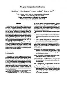
As can be seen, the estimates for RCA are close, while for KS and HC are underestimated. Based on these estimates we have computed the Delay = (1– α)*Layers + α*Length. In case α = 0, only the layers (i.e., the nodes, hence the gates) are introducing a delay, while the wires are not. By increasing α, the wires (Length) start playing a more significant role. For improving characterization, we have estimated Power as the number of Nodes. This estimate accounts for the leakage currents of all the nodes, a good approximation in subthreshold. Such an approximation does not estimate well the dynamic power, as it does not take into account the longer wires of KS and HC (again, underestimating in these two cases). Finally, the powerdelay-product (PDP) and the energy-delay-product (EDP) have been estimated in a straightforward manner as PDP = Nodes*Delay, and EDP = PDP*Delay. The results of these rough estimates can be seen in Fig. 1, where Delay, PDP, and EDP are shown for α = 0, and α = 0.25. Obviously, by increasing α the delay of the KS and HC adders increases, but KS and HC are always going to be faster than RCA (as α < 1). The more interesting results are the ones showing PDP and EDP. For α = 0 (i.e., no delay on the wires), RCA has a better PDP than KS or HC for n < 22, and competes with KS and HC for the best EDP for n < 12. For α = 0.25 the RCA gets the best PDP and EDP for any n < 32. These results should be even better, as power for KS and HC was underestimated. These plots support the claim that serial adders could achieve better PDP and EDP than parallel adders, in particular when
Power−Delay−Product
35
2000
6
30
5 1500
alpha = 0
25
4
20
1000
15
3 2
10
500 1
5 0
4 Energy−Delay−Product x 10
0
10
20
30
0
0
10
20
30
0
0
10
20
30
alpha = 0.25
4
35
3500
30
3000
25
2500
20
2000
3
15
1500
2
10
1000
5
500
0
0
10 20 30 Number of bits
0
5
x 10
4
1
0
10 20 30 Number of bits
0
0
10 20 30 Number of bits
Figure 1. Estimates of the delay, the PDP, and the EDP, with and without wires for RCA (blue), KS (red), and HC (green)
KS (circles), HC (squares), and RCA (stairs) 1 0.9
Failure probability of 32−bit adders (pf = 1%)
0.8 0.7
Figure 3. Majority multiplexed RCA where the three majority gates (restorative stages) are reduced to short-circuiting the outputs [23]
0.6 0.5 0.4
while here we use the mirrored adder gate [25] (see Fig. 4) for implementing the carry output function.
0.3 0.2
3. Device level fault/defect analysis
0.1 0
0
5
10
15 20 Number of bits
25
30
35
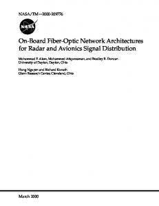
Figure 2. Estimate of the failure rates of RCA (blue), KS (red), and HC (green) versus number of bits, for a block failure rate of 1% operated in subthreshold, or when leakage power represents a large component of power consumption. Operation in subthreshold has already been devised for achieving (ultra) low power [20], [21], but has raised many questions with respect to speed and reliability. At (ultra) low voltages, soft errors will play a significant role [3], [4], let alone the higher sensitivity to variations. The solutions we have advocated for dealing with such problems are: the use of high matching [12], [10], and enhanced majority multiplexing [22]. Still, while such methods are going to enhance reliability, they will do that on top of the intrinsic reliability of the structures designed. Let us consider again the case of the three different adders: RCA, KS, and HC. We have used a very simplistic estimate (but one which again favors KS and HC), namely that the failure rate of an adder can be related to the number of Nodes as 1 – (1–ε)Nodes, where ε is the block failure rate. [Remark: A more precise estimate should start from the device failure rate, and use the number of devices inside each block—which is larger for KS and HC.] Simulation results can be seen in Fig. 2, and support the intuition that a simpler structure is more reliable. Additionally, any redundancy scheme is easier to integrate with RCA [23], so the use of a serial solution clearly becomes the best bet from a powerreliability standpoint. Majority multiplexing is a faulttolerant scheme requiring majority gates at (each) restorative stages [22]. Three different implementations have been suggested in [23]: (i) majority gates; (ii) inverters driven by short-circuited outputs; and (iii) only short-circuiting the outputs (see Fig. 3). These were analyzed using output-wired inverters for implementing the carry output function [19], [24],
Gate level multiplexing using short-circuited outputs of three mirrored adder gates is shown in Fig. 4, and corresponds to three redundant blocks (highlighted in Fig. 3). This may improve matching as well as fault tolerance [12]. Without redundancy, a failure of one transistor can make the circuit malfunction. This is not the case when redundancy is introduced, as shown here. The transistors on the schematic have been labeled to enable ease of tracking when analyzing faults/defects (see [26]). The schematic shows three mirrored adder gates sharing the same input signals and having their outputs short circuited (highlighted in Fig. 3). The schematic in Fig. 4, using a 120 nm triple well CMOS process and a substrate-biasing scheme like in [27], has been used for the simulations. The supply voltage was VDD = 200 mV. Output voltages, in mV, for al the eight possible combinations of inputs are shown in Table 1. The last column, labeled Defect(s), lists the transistors that were removed from the schematic (representing defects within the circuit) as has been done in [26]. From Table 1 it is apparent that when one or two transistors are removed from the schematics, proper functionality is still maintained. Only when three transistors at a certain position (e.g., P1, P6 and P11) were removed, the circuit stated to err. This can be seen for input 010, where the logic high level (200 mV) is not correct anymore (25.6 mV). In this case, the collective effort of the functional PMOS transistors is not enough to pull the output voltage above 25.6 mV (which represents the opposite logic value). Removing X
X
Vdd
Y P1
P2
P6
Out
N2
N3
N5
Gnd
P11
P10
N8
N10
Gnd
P14
P15
Out
Z
N9
N6
P12
P13
Out
N7
Vdd
Y
P9
Z
N4
N1
P7
P8
P5
P3
Z
X
Vdd
Y
P4
N14
N11
N12
N13
N15
Gnd
Figure 4. Multiplexed mirrored adder gates with short-circuited outputs
Table 1. Output of three short-circuited mirrored adder gates 000 199.9 199.9 199.9 199.9 199.9 199.9 199.8
001 199.6 199.6 199.6 199.6 199.4 198.9 10.6
010 199.6 199.4 198.9 25.6 199.4 198.9 10.3
011 0.193 0.168 0.146 0.119 0.140 0.091 0.040
100 199.5 199.5 199.5 199.5 199.5 199.5 199.5
transistors P3, P8 and P11 results in faulty output values for input vectors 001 and 010.
4. Low-power microachitectures It has become a norm that whenever CMOS scales from one technology node to the next lower node, transistor switching speeds increase. However, this trend is likely to diminish as we approach the physical limits of silicon. It is also widely accepted that with further miniaturization there will be a rise in leakage currents. This has contributed to the pursuit of research on (ultra) low voltage operation [20], [21], [24], [26]– [32]. Operation in subthreshold sacrifices speed, however, power dissipation is reduced by orders of magnitude compared to standard above threshold operation. In fact, in a recent work [26], we have shown that femto-Joule full adders are feasible. That is why, RCAs using output-wired inverters have been designed and simulated in subthreshold [19]. The simulation results from [19] support the theory (Section 2), as the results are similar to the ones presented in Fig. 1 for α = 0.25. They show that when wires are properly accounted for, parallel adders will dissipate
101 0.159 0.161 0.163 0.164 0.131 0.111 0.083
110 0.157 0.147 0.133 0.119 0.134 0.107 0.080
111 0.040 0.038 0.036 0.034 0.032 0.024 0.017
Defect(s) None P1 P1 & P6 P1, P6 & P11 P3 P3 & P8 P3, P8 & P13
much more power than serial ones. A modest 10-20% (20 to 50 mV) increase in VDD makes RCA as fast as KS, while the power consumption is still smaller [19]. One interesting aspect to analyze is the effect of varying/optimizing VDD to reconcile the conflicting power and speed metrics. We determine optimal VDD differently from the approach reported in [31] where Vth is varied as well as VDD. Our approach holds Vth constant and varies only VDD. Power supply voltages starting from Vth/2 (subthreshold) up to 2(Vthn + |Vthp|) ~ 4Vth allow for shorter delays at the expense of increased power. Table 2 shows that from Vth/2 to about 4Vth the delay is decreased and the power is increased by well over two orders of magnitude. These are significant, and show that varying VDD in such a range could prove rewarding both for speed and for power. Simulations have been performed at 180 nm and 70 nm (using BPTM [33] with inherent Vthn of 0.2 V and Vthp of –0.22 V). To get a better understanding, the traces showing power, PDP and EDP are presented in Fig. 5. They are based on a 32-bit RCA having all 32 stages functioning correctly. The figures in the top row were obtained from the 180 nm CMOS, while those of the second (bottom) row are
Table 2. 32-bit RCA simulations for VDD varying from 100 mV to 700 mV (70 nm) VDD (mV) Vth/2 100 150 Vth 200 250 300 350 2Vth 400 450 500 550 3Vth 600 650 700
Delay (ns) 3,760.00 1,438.00 543.00 222.00 102.00 53.10 32.14 21.96 16.48 13.34 11.31 9.91 8.84
Current (nA) 180 226 362 847 1,948 3,878 7,115 12,475 18,241 24,823 30,356 35,360 42,607
Power (nW) 18.00 33.90 72.40 211.75 584.40 1,357.30 2,846.00 5,613.75 9,120.50 13,652.65 18,213.60 22,984.00 29,824.90
PDP (fJ) 67.68 48.75 39.31 47.01 59.61 72.07 91.47 123.28 150.31 182.13 205.99 227.77 263.65
EDP (fJ*ns) 254,477 70,100 21,347 10,436 6,080 3,827 2,940 2,707 2,477 2,430 2,330 2,257 2,330
Power
−4
−12
10
Power−Delay−Product
10
−16
Energy−Delay−Product
10
−6
10
−18
10 −13
10 −8
10
−20
10 −10
10
0.2
−14
0.4
0.6
0.8
−4
10
0.2
0.4
0.6
0.8
−12
10
0.2
0.4
0.6
0.8
−18
10
10
−5
10
−19
10 −6
−13
10
10
−20
10
−7
10
−8
10
−14
0.2
0.4 Vdd
0.6
10
−21
0.2
0.4 Vdd
0.6
10
0.2
0.4 Vdd
0.6
Figure 5. Effect of varying VDD (32-bit RCA) on power, PDP, and EDP (180 nm top, 70 nm bottom) based on the simulation results at the 70 nm technology. Table 2 (and Fig. 5) clearly depict the relationship between increasing VDD and the current/ power. A designer can easily make a choice depending on the design requirements. Thus, if the goal is minimum power consumption, the circuit should operate with the lowest possible VDD [32]. If speed is a concern, VDD should be increased with the understanding of the associated penalty in power consumption. Dynamically adapting VDD between subthreshold and above threshold should prove rewarding for (ultra) low power operations, while attempting to keep performance reasonably high.
5. Concluding remarks Device miniaturization leads to an increased probability of failures, increased (static) power dissipation (due to leakage currents), and a degradation in performance due to (longer) wire delays. Reduction of power supply voltages has already been adopted as a means of reducing dynamic power, but can also reduce static power. In this study we have tackled the faulttolerance and (ultra) low power-speed trade-off issues. We have shown that serial addition can match the speed of parallel addition when operating in subthreshold, while still dissipating less (power). This makes a serial adder, which also has less wiring complexity, a very good choice for (ultra) low
power/voltage designs. Additionally we have shown that a serial adder is also a better choice for incorporating redundancy (for higher defect- and faulttolerance). Because of significant speed degradation in subthreshold we have investigated the influence of varying VDD from Vth/2 up to about 4Vth. This reduces delays by well over two orders of magnitude. The approach we are advocating should allow designs to be operated in subthreshold if speed is not a concern, while operating at higher speeds at VDD > Vth when performance is important (at the expense of increased power dissipation). It must be noted here that this range of VDD values has not been properly used, and that it could provide interesting power-speed trade-offs (see the inflection points of the PDP and the EDP in Fig. 5). Two further directions of research are promising. The first one is to use carry-skip adders [34] for higher speeds. With a regular snake-like layout all the wires, including the ones for skipping, could have the same minimum length, but incorporating redundancy will be a more difficult task. The second one is intended both for speeding up addition and reducing the power consumption, and is based on finding optimal substrate bias voltages. As recently shown in [35], a 32-bit HC in 180 nm operating at nominal VDD has seen delay reduced by 10%, power reduced by 30-60%, and PDP reduced by up to 37% when optimizing the substrate bias. It would be interesting to investigate how these would translate for (ultra) low supply voltages.
References [1] International Technology Roadmap for Semiconductors, 2004. Available: http://public.itrs.net/ [2] C. Constantinescu, “Trends and challenges in VLSI circuit reliability,” IEEE Micro, vol. 23, Jul. 2003, pp. 14-19. [3] P. Sivakumar et al., “Modeling the effect of technology trends on soft error rate of combinatorial logic,” Proc. Intl. Conf. Dependable Sys. Networks, Washington, USA, Jun. 2002, pp. 389-398. [4] P. Sivakumar et al., “Exploiting microarchitectural redundancy for defect tolerance,” Proc. Intl. Conf. Comp. Design, San Jose, USA, Oct. 2003, pp. 481-488. [5] K. Nikolić, A.S. Sadek, and M. Forshaw, “Fault-tolerant techniques for nanocomputers,” Nanotechnology, vol. 13, Jun. 2002, pp. 357-362. [6] J. Han, and P. Jonker, “A system architecture solution for unreliable nanoelectronic devices,” IEEE Trans. Nanotech., vol. 1, Dec. 2002, pp. 201-208. [7] A.S. Sadek, K. Nikolić, and M. Forshaw, “Parallel information and computation with restitution for noisetolerant nanoscale logic networks,” Nanotechnology, vol. 15, Jan. 2004, pp. 192-210. [8] J. von Neumann, “Probabilistic logics and the synthesis of reliable organisms from unreliable components,” in C.E. Shannon and J. McCarthy (Eds.), Automata Studies, Princeton Univ. Press, 1956, pp. 43-98. [9] J.R. Heath et al., “A defect-tolerant computer architecture: Opportunities for nanotechnology,” Science, vol. 280, Jun. 12, 1998, pp. 1716-1721. [10] S. Tatapudi, and V. Beiu, “Split-precharge differential noise immune threshold logic gate (SPD-NTL),” Proc. Intl. Work-conf. Artif. Neural Networks, Menorca, Spain, Jun. 2003, pp. 49-56. [11] M. Sulieman, and V. Beiu, “Design and analysis of SET circuits: Using MATLAB and SIMON,” Proc. IEEE Conf. Nanotech., Munich, Germany, Aug. 2004, pp. 618-621. [12] S. Aunet, and M. Hartmann “Real-time reconfigurable threshold elements and some applications to neural hardware,” Proc. Intl. Conf. Evolvable Sys., Trondheim, Norway, Mar. 2003, pp. 365-376. [13] A. Schmid, and Y. Leblebici, “Robust circuit and system design methodologies for nanometer-scale devices and single-electron transistors,” Proc. IEEE Conf. Nanotech., San Francisco, USA, Aug. 2003, vol. 2, pp. 516-519. [14] A. Weinberger, and J.L. Smith, “A logic for high-speed addition,” Natl. Bur. Stand. Circ. 591, 1958, pp. 3-12. [15] P.M. Kogge, and H. Stone, “A parallel algorithm for the efficient solution of a general class of recurrence equations,” IEEE Trans. Comp., vol. 22, Aug. 1973, pp. 786-793. [16] R.E. Ladner, and M.J. Fischer, “Parallel prefix computations,” J. ACM, vol. 27, Oct. 1980, pp. 831838. [17] R.P. Brent, and H.T. Kung, “A regular layout for parallel adders,” IEEE Trans. Comp., vol. 31, Mar. 1982, pp. 260-264.
[18] T. Han, and D.A. Carlson, “Fast area-efficient VLSI adders,” Proc. Symp. Comp. Arith., Como, Italy, May 1987, pp. 49-56. [19] V. Beiu, A. Djupdal, and S. Aunet, “Ultra low power neural inspired addition: When serial might outperform parallel architectures,” Intl. Work-conf. Artif. Neural Networks, Barcelona, Spain, Jun. 2005, in press. [20] C.A. Mead, “Neuromorphic electronic systems,” Proc. IEEE, vol. 78, Oct. 1990, pp. 1629-1636. [21] G. Schrom, and S. Selberherr, “Ultra low-power CMOS technologies”, Proc. Intl. Annual Semicond. Conf., Sinaia, Romania, Oct. 1996, vol. 1, pp. 237-246. [22] S. Roy, and V. Beiu, “Multiplexing schemes for costeffective fault-tolerance,” Proc. IEEE Conf. Nanotech., Munich, Germany, Aug. 2004, pp. 589-592. [23] V. Beiu et al., “The vanishing majority gate: Trading power and speed for reliability,” Proc. NanoArch’05, Palm Springs, USA, May 2005, in press. [24] S. Aunet et al., “Reconfigurable subthreshold CMOS perceptron,” Proc. Intl. Joint Conf. Neural Networks, Budapest, Hungary, Jul. 2004, pp. 1983-1988. [25] D. Hampel, K.J. Prost, and N.R. Scheinberg, “Threshold logic using complementary MOS device,” U.S. Patent 3900742, Aug. 19, 1975. [26] S. Aunet, and V. Beiu, “Ultra low power fault tolerant neural inspired CMOS logic,” Proc. Intl. Joint Conf. Neural Networks, Montreal, Canada, Jul. 2005, in press. [27] A. Bryant et al., “Low power CMOS at Vdd = 4kT/q,” Proc. Device Res. Conf., Notre Dame, USA, Jun. 2001, pp. 22-23. [28] J. Nowak, “Maintaining the benefits of CMOS scaling when scaling bogs down,” IBM J. Res. & Dev., vol. 46, Mar.-May 2002, pp. 169-180. [29] S. Aunet et al., “200 mV full adder based on a reconfigurable CMOS perceptron,” Proc. Intl. Conf. Signals & Electr. Sys., Poznań, Poland, Sep. 2004, pp. 237-240. [30] B.H. Calhoun, A. Wand, and A. Chandrakasan, “Device sizing for minimum energy operation in subthreshold circuits,” Proc. Custom IC Conf., Orlando, USA, Oct. 2004, pp. 95-98. [31] A. Wang, A.P. Chandrakasan, and S. Kosonocky, “Optimal supply and threshold scaling for subthrehold CMOS circuits,” Proc. Annual Symp. VLSI, Pittsburgh, USA, Apr. 2002, pp. 5-9. [32] A.P. Chandrakasan, S. Sheng, and R.W. Brodersen, “Low-power CMOS digital design,” IEEE J. Solid-State Circ., vol. 27, Apr. 1992, pp. 473-484. [33] Y. Cao et al., “New paradigm of predictive MOSFET and interconnect modeling for early circuit simulations,” Proc. Custom IC Conf., Orlando, USA, May 2000, pp. 201-204. [34] T. Kilburn, D.B.G. Edwards, and D. Aspinall, “Parallel addition in digital computers: A new fast ‘carry’ circuit,” Proc. IEE, vol. 106, pt. B, Sep. 1959, pp. 464– 466. [35] Q.-W. Kuo, V. Sharma, and C.C.-P. Chen, “Substratebias optimized 0.18 µm 2.5 GHz 32-bit adder with postmanufacture tunable clock,” Proc. Intl. Symp. VLSI Tech., Hsinchu, Taiwan, Apr. 2005, in press.