On the Composition and Reuse of Viewpoints across Architecture Frameworks Rich Hilliard Freelance software systems architect
[email protected]
Ivano Malavolta, Henry Muccini, Patrizio Pelliccione Dipartimento di Informatica, Universit`a dell’Aquila, Italy {ivano.malavolta,henry.muccini,patrizio.pelliccione}@univaq.it
Abstract—A central aspect of architecting is architecture description. Architecture descriptions take many forms and serve many purposes throughout the life cycle of development, operation and maintenance activities. The use of multiple views – diverse representations for distinct audiences and uses – has been a major tenet of architecture description since the earliest work in software architecture. This tenet has been codified in various ways. Most practising software architects must operate within the confines of a prescribed architecture framework (AF) or architecture description language (ADL) as dictated by their organization or client. Current AFs and ADLs are defined with varying degrees of rigour and offer varying levels of tool support; furthermore, these resources are often closed, making it difficult for the architect to tailor a representational solution to the specific challenges of the project at hand. In this paper we propose an automated infrastructure to support the architecture description-related activities of the architect. This infrastructure facilitates customization, composition and reuse of the architect’s representational resources (AFs, ADLs and their constituents) to meet project-, domainand organization-specific needs. The proposed approach builds upon the conceptual foundations of ISO/IEC/IEEE 42010 for architecture description. The approach has been evaluated in the context of a complex, real-world, public transportation system. Keywords-software architectures; architecture description language; architecture framework; model-driven engineering; megamodelling; viewpoints
I. I NTRODUCTION The use of multiple views has become standard practice in industry [1], [2], [3]. A survey we recently conducted on the industrial needs from architectural languages [4] revealed that 85% of the 48 interviewed practitioners use multiple views when architecting a software system, with a total of nine different views and a predominant use of structural, behavioral, and physical views reported. One consequence of the tenet of using multiple views is a growing body of viewpoints that have become available (such as [1], [5], [6]) and supported by Architecture Description Languages (ADLs). A second consequence is the rise of architecture frameworks as coordinated sets of viewpoints. Most practising software architects must operate within an architecture framework prescribed for them by their organization or client. Current frameworks are defined with varying Accepted to WICSA/ECSA 2012 (http://www.wicsa.net), 20–24 August, Helsinki.
degrees of rigor and offering varying levels of automated tool support. However, architecture frameworks tend to be closed; that is, architecture frameworks mainly focus on a closed set of stakeholder concerns, viewpoints, ADLs, etc. Thus, (i) it is difficult to re-use viewpoints when defining new frameworks to be used in different organizations or domains; and (ii) it is difficult to define consistency rules among viewpoints once and forever, since such rules are not re-usable as first-class artefacts. Based on our survey [4], although automated consistency checking between views is advocated as an important feature for future ADLs, about 50% of the respondents check view consistency manually (i.e., with no formalized method). Moreover, (iii) current ADLs do not provide systematic mechanisms for adding new views (about 48% of the respondents to our survey had to extend their ADLs for adding new views). Similarly, architectural frameworks can be difficult to extend, and most do not provide mechanisms to handle architecture concerns not anticipated by the framework’s creators. With the aim of taking a step towards addressing these current limitations, the goal of this paper is to provide an infrastructure, called M EGAF (MEGamodeling Architecture Frameworks), for building reusable architecture frameworks. Using the conceptual foundations of ISO/IEC/IEEE 42010 [7], we show how automated support for viewpoints, as first-class entities, can provide architects with improved support for architectural modelling and its application to the analysis of architecture descriptions. Our approach also provides a basis for sharing and reuse of such capabilities across projects (and the community) as an interface to a repository of reusable architectural knowledge. More precisely, M EGAF allows software architects to create new architecture frameworks by means of mechanisms: i) to store architecture descriptions and their constituents (including views, viewpoints, stakeholders and system concerns); ii) to define correspondences among views, viewpoints, stakeholders, system concerns and their elements; iii) to enforce consistency and completeness checks based on defined architectural relationships and rules among elements. M EGAF is realized by means of megamodeling techniques [8] that provide appropriate ways for handling different type of models. Intuitively, a megamodel is a model of which at least some elements represent and/or refer to models or metamodels. By considering viewpoints, stake-
holders, and concerns as first-class elements of a megamodel, M EGAF allows software architects to define, store, and combine them in order to define the desired architecture framework. By representing architecture descriptions as sets of models we are able, for instance, to define links among different views, to define links between the models that constitute each view, to create and store views in libraries, and check adherence of the architecture description to the framework. The viability of M EGAF is demonstrated via its application to a real-world case study called BusOnAir. This work elaborates on the arguments discussed in a previous position paper [9] by (i) presenting a detailed description of the M EGAF model-driven infrastructure (i.e., its underlying megamodel), (ii) describing how M EGAF allows one to perform consistency and completeness checks on architecture descriptions, (iii) applying M EGAF on a realworld case study, (iv) discussing in detail its benefits and drawbacks, and (v) illustrating related work in-depth. The remainder of this paper is structured as follows. Section II introduces architecture frameworks, the conceptual foundations of ISO/IEC/IEEE 42010 for architecture description, and highlights the main existing problems that represent the motivation of this paper. Section III and IV represent the heart of this paper and present our approach for realizing architecture frameworks and its implementation. Section V applies the approach to the BusOnAir case study, while benefits and drawbacks are discussed in Section VI. Section VII compares M EGAF with related work and the paper concludes with Section VIII. II. A RCHITECTURE D ESCRIPTION In this paper, we build upon the conceptual foundations of ISO/IEC/IEEE 42010:2011, Systems and software engineering — Architecture description [7] to investigate the essential elements of architecture description and support the architect’s architecture description-related activities. ISO/IEC/IEEE 42010 is the joint ISO and IEEE revision of IEEE Std 1471, first published in 2000 [3]. The standard is method-neutral: it is intended for use by architects employing various architecting1 methods. The standard addresses architecture description (AD): the practices of recording software, system and enterprise architectures so that architectures can be understood, documented, analysed and realized. Architecture descriptions are created by architects and used by architects and other stakeholders throughout all stages of a system’s life cycle, from development through operation and maintenance. Architects create ADs for many purposes (see [7, §4.4]). To achieve these purposes and to meet the diverse needs of a system’s stakeholders, architecture descriptions take on many forms, from informal (sketches on the back of an envelope or drawings on a 1 When we refer to architecture or architecting in this paper, we intend to include equally software architecture, system architecture and enterprise architecture, unless otherwise qualified.
whiteboard) to rigorously specified models. Because an architecture must typically address a variety of issues for a variety of stakeholders, many conventions (notations, kinds of model, analysis techniques) are utilized. The standard defines three mechanisms for architecture description: 1) architecture viewpoints: common ways of expressing recurring architectural concerns reusable across projects and organizations; 2) architecture frameworks (AFs): coordinated set of viewpoints for use within a particular stakeholder community or domain of application; 3) architecture description languages (ADLs): any mode of expression used in an architecture description. Architects then apply these mechanisms to produce architecture descriptions of specific systems of interest (such as software applications, enterprises, product lines, etc.). These three mechanisms are each built on a few basic elements defined by the standard. The standard specifies requirements on each of these primitive elements used to create architecture descriptions with the further goal of promoting understandability, interoperability and overall improvement of the field of architecting by having a common terminology and conceptual basis. An architecture viewpoint encapsulates model kinds framing particular concerns for a particular audience of system stakeholders. The concerns determine what the model kinds must be able to express: e.g., functionality, security, reliability, cost, deployment, etc. A model kind determines the notations, conventions, methods and techniques to be used. Viewpoints, defining the contents of each architecture view, are built up from one or more model kinds and correspondence rules linking them together to maintain consistency. Viewpoints, like patterns and styles, are a form of reusable architectural knowledge for solving certain kinds of architecture description problems derived from best practices. Viewpoints originated in the 1970s (in Ross’ Structured Analysis) and refined in [10]. Architecting methods often define one or more viewpoints, e.g. [1], [5], [11], [12]. A. Architecture Frameworks and ADLs Building on the viewpoint mechanism, an architecture framework is a coordinated set of viewpoints, conventions, principles and practices for architecture description within a specific domain of application or community of stakeholders. Architecture frameworks originated in the 1970s; Zachman popularized the term through his information systems architecture framework [13]. Since then, many frameworks have been proposed, published and used, in a variety of domains and defined with varying degrees of formality. Recent frameworks include the ISO Reference Model for Open Distributed Processing, GERAM, TOGAF, and MODAF. For an extensive survey of frameworks, see [14].
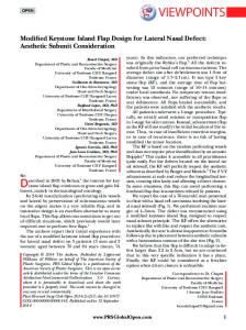
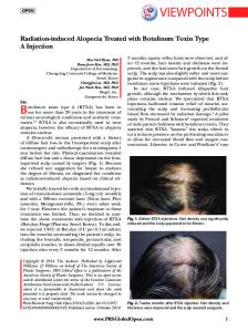
Figure 1. Content model of an architecture framework (following ISO/IEC/IEEE 42010)
for addressing it. Since any framework or ADL is finite, this is a common occurrence. Uniform definitions offer several opportunities: • improved basis for consistency and model checking; • to allow architects to compare and contrast AF and ADL offerings and choose from among them the best approaches to the problem at hand; • customization of AD mechanisms to the project or organization; • to compose new AFs and ADLs by mixing-andmatching of existing mechanisms; • to interoperate across mechanisms (e.g., using a tool for one model kind to analyze a model of another under translation; III. T HE SOLUTION
An architecture framework is a prefabricated knowledge structure that architects use to organize an architecture description into complementary views. For further discussion of the content model and architecture frameworks mechanism, see [15]. The content model for an architecture framework is illustrated in Figure 1. An architecture description language is a collection of model kinds selected to frame one or more concerns. The model kinds may or may not be organized into viewpoints. Some ADLs are very simple, defining a single model kind. For example, Acme provides one model kind suited for specifying components, connectors, ports and roles [16]. Other “classical” ADLs (from the 1990s) include Darwin [17], R APIDE [18] and Wright. More recent ADLs can be quite elaborate with numerous model kinds and viewpoints (such as AADL [19], ArchiMate [20], SysML and xADL [21]). Beyond these minimal requirements linking stakeholders and concerns to model kinds and viewpoints, and correspondence rules linking views and models together, creators of frameworks and ADLs are free to add other content to aid architects, such as tools, guidelines, principles, patterns, styles, heuristics and so on. B. Current Limitations and Challenges Existing architecture frameworks and architecture description languages have been defined in a variety of ways with varying degrees of rigor. Using the primitive elements described in the previous section, the standard provides a basis for specifying diverse frameworks and ADLs in a uniform manner as first-class entities. Furthermore, current AFs and ADLs are for the most part closed: their developers expect each framework or ADL is all that an architect will ever need. E.g., frameworks may be tailored downward, some viewpoints or model kinds omitted in use, but rarely are means for extension provided. Usually, the metamodel of a framework is a fixed system. As a consequence, if a framework or ADL does not frame a particular concern (e.g., safety), there may be no provisions
As mentioned in the introduction, and further discussed in Section VII, although many architecture frameworks have been proposed in recent years, they are too rigid to perfectly match all stakeholder’s needs. Moreover, these architectural frameworks are not consistently defined and cannot be extended. A. Conceptual overview of MEGAF In this section we present M EGAF, which is an infrastructure that enables software architects to realize their own architecture frameworks specialized for a particular application domain or community of stakeholders. It offers an effective way of managing, storing, retrieving, and combining existing viewpoints, by properly selecting and reusing models previously defined and resident in M EGAF. Architecture frameworks that can be realized by using M EGAF conform to ISO/IEC/IEEE 42010 [7]. Once an architecture framework has been defined within M EGAF, it can be used to create architecture descriptions of systems-of-interest. Architecture descriptions are easily made to adhere to the architecture framework used to realize them. For instance, the realized architecture models adhere to the conventions of their model kinds as defined by the architecture framework and its viewpoints. Moreover, the M EGAF infrastructure enables the architect to express and enforce relations both between various elements within an architecture description and across architecture descriptions. This would be particularly useful while producing an architecture description for systems of systems and Cyber Physical Systems [22]. To better understand the characteristics of M EGAF we describe two usage scenarios: • Realizing architecture descriptions: architects (and their organizations) are most likely to use a predefined architecture framework. These end-users do not create new viewpoints, but use an existing framework “out of the box”; however, they may need to customize the presentation of architecture descriptions for various
•
stakeholder audiences or integrate that framework with existing project tools or artifacts. Realizing a new architecture framework: architects create new viewpoints and model kinds to handle particular system concerns (e.g., fault-tolerance) not addressed by their current framework. They would then integrate those by linking them with other existing representations.
B. Consistency Checks An important aspect of M EGAF is the support that it offers to define conformance checks. These checks can be defined using OCL,2 at different levels, as explained here: • Conformance of an architecture framework with ISO/IEC/IEEE 42010: requirements from the standard are encoded within M EGAF and they are enforced through the mechanisms for models and metamodels in the model-driven engineering context. Additional rules have been defined to check constraints other than those imposed by the ISO/IEC/IEEE 42010. For instance, a rule may be added to ensure that for each model kind, suitable conventions have been defined (see Listing 1). Listing 1.
A conformance check for ISO/IEC/IEEE 42010
1 context ModelKind 2 inv is_convention_defined : 3 Convention.allInstances()->exists(e | e.modelKind = self) •
•
The standard also specifies other desired checks that have been encoded and automated in M EGAF. For instance, even though an architecture description could conform to zero, one or more architecture frameworks, it is useful to have automation to check the adherence of an architecture description to a particular architecture framework. The standard defines requirements (cf. [7, §6.2]) to ensure that each stakeholder, concern, and viewpoint identified in the architecture framework has been considered in the architecture description, and moreover that each correspondence rule identified in the architecture framework holds in the architecture description. Additional rules can be defined as part of a specific architecture framework. For instance, Listing 2 shows a correspondence rule checking that for each component defined within a UML model used in a specific viewpoint, a state machine is defined in another UML model used in another viewpoint (due to space limitations, we do not show the isLinkedToStateMachine auxiliary function in the listing). Listing 2.
Example of framework-specific rule
1 context ArchitectureModel 2 inv check_comp_stateMachine : 3 Component.allInstances->select(e | not e. isLinkedToStateMachine()).isEmpty()
•
Finally, architects can define correspondence rules, using OCL, within the architecture description particular to the system-of-interest. For instance, rules can be defined to ensure the consistency among specific views or among models defined inside a view.
IV. R EALIZATION OF THE A PPROACH A. Megamodeling: modeling in the large Megamodeling has been proposed with the aim of supporting modeling in the large, i.e. dealing with models, metamodels, and their properties and relations. Intuitively, a megamodel is a model in which some elements represent and/or refer to models or metamodels [23]. While a metamodel specifies properties and rules governing model construction for a specific model kind, a megamodel specifies properties and rules governing model construction, including multiple models and metamodels. Megamodeling operations support the management of large libraries of artifacts that, as said before, could be models and metamodels. Megamodeling offers the possibility to handle model (and metamodels) as first-class entities, to specify relationships between them and to navigate among them. This is fundamental in M EGAF since architecture views generally have important relations (correspondences) defined among them. Furthermore, we treat all heterogeneous architecture artifacts as models and assume that each model has a metamodel, in order to have a homogeneous infrastructure. This enables the management of complex artifacts since that complexity is defined and encoded in their metamodels, thus enabling programmatic management of (even complex) models. This assumption follows a basic tenet of ISO/IEC/IEEE 42010: each view conforms to a viewpoint, and each architecture model conforms to a model kind. The assumption also seems reasonable in light of the recent Doc2Model (Document to Model3 ) Eclipse project for parsing structured documents to produce EMF4 models.
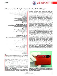
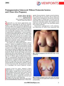
Figure 2.
Basic megamodeling conceptual framework
Figure 2 shows an excerpt of the megamodeling conceptual framework, as presented in [24]. In the following, we will refer to a metamodel of a megamodel as a metamegamodel. The main types of models are: • Terminal Models, which represent the real system architecture and conform to some metamodels; 3 http://eclipse.org/proposals/doc2model
2 OMG
Object Constraint Language: http://www.omg.org/spec/OCL
4 http://www.eclipse.org/modeling/emf
MetaModels, which define domain-specific concepts and conform to metametamodels; • MetaMetamodels, which provide generic concepts for metamodels specification and conform to themselves. MetaModels and MetaMetaModels are called Reference Models since they define the concepts that can be instantiated in other models; so they can be considered as a reference for all the models conforming to them. Figure 2 shows different kinds of terminal models: • Transformation Models, which are used to define transformations between models; • Weaving Models, which are used to define relationships among models; • MegaModels, which are used to support the megamodeling process. The basic megamodeling conceptual framework described above has been extended in many ways for different purposes. One recent extension proposes the use of megamodels in combination with weaving models [25] for coordinating sets of models. In that work, a megamodel represents all models involved in a given context and the various relationships between them, while weaving models are used to represent different kinds of fine-grained relationships between the elements contained in the models. The navigability and traceability extension in [25] had a strong impact on our work since it allows software architects to define relations between architectural models at two levels of abstraction: model-level and model element-level, thus promoting a definition of more accurate correspondences between the architectural elements involved in M EGAF. As a concrete implementation of megamodeling, we refer to the AMMA platform,5 as presented in [26]. In particular, a dedicated component of the AMMA platform handles megamodel management, it is called AM3 [24]. In AM3, a megamodel records all available resources and acts as an MDE repository. AM3 is extensible, and thus it allows developers to extend its base metamegamodel by providing new concepts in a separate metamegamodel. Under this perspective, architecture concepts can be defined as an extension of the base metamegamodel; in so doing, it is possible to navigate architecture models and establish typed correspondences among them by reusing the AM3 extensible platform. •
B. Megamodeling Architecture Frameworks As discussed in Section II, ISO/IEC/IEEE 42010 defines a conceptual model of architecture description. In this work we exploit megamodeling techniques to put in a concrete form the concepts and requirements expressed in ISO/IEC/IEEE 42010. M EGAF is built upon a generic metamodel for software architecture megamodels; this metamodel is called GMM4SA (Global Model Management 5 http://www.sciences.univ-nantes.fr/lina/atl/AMMAROOT
for Software Architectures). The relationships expressed in ISO/IEC/IEEE 42010 have been encoded in GMM4SA, so that each megamodel conforming to it must satisfy those relationships in order to be valid. Additional relationships and rules are defined via OCL. Models conforming to GMM4SA contain other models as first-class entities, including: architecture descriptions, architecture models and their model kinds, correspondences and correspondence rules, views and their viewpoints, stakeholders, and concerns. Developing a metamegamodel allows one to: • • •
represent architecture elements as model instances, define relationships and correspondences among architecture elements in a natural and straightforward way, provide a suitable engine for automating consistency checks among architectural elements.
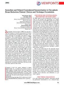
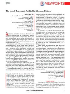
As shown in Figure 3, relationships expressed in ISO/IEC/IEEE 42010 have been modeled in GMM4SA, so that each megamodel conforming to it must satisfy those relationships in order to be valid. Additional relationships and rules, specific to an architecture framework or organization are defined by means of weaving models and OCL; these implement correspondences and correspondence rules, respectively. Therefore, each architecture description (AD) element (e.g. view, viewpoint, stakeholder, concern, etc.) can be explicitly represented via a model or a model element depending on its granularity (e.g. Concern becomes a metaclass that can be instantiated as many times as needed to model different concerns, whereas ArchitectureModel becomes a metaclass that references an external resource, so its instances are externally defined models). In GMM4SA six metaclasses extend concepts belonging to the base metamegamodel, i.e., those that are colored in Figure 3. Moreover, in GMM4SA there are five metaclasses whose instances are external models, they are: (i) ADElement is an abstract metaclass representing generic architecture description elements as defined in ISO/IEC/IEEE 42010. All metaclasses within the GMM4SA metamodel extend ADElement (for the sake of readability this relationship is omitted from the figure). ADElement inherits from IdentifiedElement and Entity of AM3, so that it has a unique identifier, may be linked to other identified elements and may be navigated via the AM3 entities navigator. (ii) ArchitectureDescriptionLanguage inherits from Metamodel in AM3 since an architecture description language can be represented as a metamodel to which an ArchitectureModel may conform. By doing this, we can reuse standard model-driven mechanisms to check whether an architecture model conforms to its corresponding architecture description language. In GMM4SA, architecture frameworks, viewpoints and model kinds can have an associated metamodel as well; for the sake of simplicity we did not include
Figure 3.
Extract of GMM4SA
the corresponding association reference in the GMM4SA metamegamodel represented in Figure 3. (iii) ArchitectureModel inherits from TerminalModel in AM3. This allows to store ADLs and architecture models as external models, thus promoting their reuse. (iv) CorrespondenceRule inherits from LocatedElement of AM3 since in M EGAF a correspondence rule is specified with OCL rules defined in an external (and so to be located) file. (v) Finally, Correspondence inherits from the ModelWeaving metaclass of the basic metamegamodel since a correspondence is a specific kind of weaving relationship; it refers to a weaving model linking two or more architecture description elements. As described above, GMM4SA supports two mechanisms to define correspondences among AD elements: the first is Correspondence that allows architects to define weaving relationships between any elements in the megamodel; the second is CorrespondenceRules expressed in OCL. These rules govern the various correspondences that have been defined between types of element within the megamodel. Correspondences are extremely important to enable the consistency and completeness checks described in Section III.
V. T HE B US O NA IR C ASE S TUDY In this chapter we focus on the application of M EGAF to a real-world case study called BusOnAir. The project is about a generic information system for managing real-time information about public transportation systems and making them available to the user by means of a set of web services and a dedicated mobile application.6 Fundamentally, this case study can be divided into two main phases: 1) Architecture Framework definition. In this phase a dedicated architecture framework for the BusOnAir project is created in order to precisely focus on its specific peculiarities and technological aspects. Section V-A will focus on this part of the case study. 2) Architecture Description development. In this phase the defined architecture framework is used to create an architecture description of the BusOnAir system. So, architecture views are developed in accordance with each required viewpoint in the framework and correspondences between views are checked with respect to the correspondence rules defined in the framework, Section V-B will focus on this part of the case study. 6 BusOnAir
prototype: http://www.busonair.eu
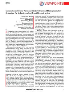
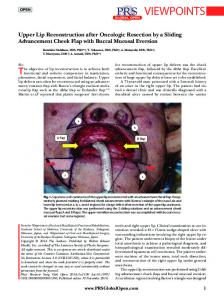
A. The BOAAF Framework In this section we use M EGAF to define BOAAF, the BusOnAir Architecture Framework. It is specifically intended for developing the architecture descriptions of systems which are similar to BusOnAir. Figure 4 shows an overview of the resulting architecture framework. For simplicity, we do not show the various relationships that exist among elements within the BOAAF architecture framework (e.g., which concerns are held by a specific stakeholder, which ADLs belong to a given architecture viewpoint, etc.); the interested reader can refer to [27] for further details on the BOAAF architecture framework.
Figure 4.
Overview of BOAAF
The upper part of the figure shows the BusOnAir system stakeholders and their concerns which drive the BusOnAir architecture. The following stakeholders are considered and identified: software architect, system engineer, end-user, and developer. The various concerns shown in the figure represent a subset of the actual concerns held by stakeholders with respect to the BusOnAir system; here we mainly focus on: modularity, distribution, concurrency, dependability, and the use of the REST paradigm for data communication. The BusOnAir system uses three architecture viewpoints. The System viewpoint is used to break down the BusOnAir system into a set of components, to show how they relate to each other, and to identify which components are “more sensible” with respect to dependability. The Behaviour viewpoint is used to reason about how the various components of BusOnAir can be executed concurrently, and to check some properties related to dependability (such as deadlock freedom of the components, and their reliability). The WebServices viewpoint is used to describe the RESTful API of BusOnAir. In the lower part of Figure 4 we show the ADLs we
selected for describing the BusOnAir architecture. More specifically, the architecture view governed by the System viewpoint will contain two model kinds: the first one uses UML component diagrams for describing the various components of the BusOnAir system, the second one uses Diaspec, a declarative language for describing applications that orchestrate entities interacting with an environment (i.e., all the components which will be deployed on the buses) [28]. Diaspec provides a Structural model kind with facilities for code generation and simulation, while UML provides a Component model kind which may be used for sharing architectural knowledge among the different stakeholders involved in the project. UML was chosen also as a good starting point for defining the behaviour of the system (via state machine diagrams) and for natively associating behavioural specifications to the UML components of the system. The Behaviour viewpoint has two model kinds as well: the first is called Dynamic model kind and utilizes a Finite State Process (FSP, [29]) language for describing the behaviour of the components of BusOnAir from a more formal perspective, which allows architects to perform property checks and deadlock freedom analysis. The second model kind, called State Machine, utilizes UML state machine diagrams; in this case also UML is chosen for communication purposes. A correspondence rule is defined in the BOAAF framework for checking that each UML component in the System viewpoint contains a state machine describing its behaviour in the Behaviour viewpoint. The WebServices viewpoint will comprise a single model kind called REST for specifying REST services (RESTLANG in the figure). It should be noted that M EGAF provides a built-in mechanism for performing some checks. Indeed, M EGAF contains rules that help architects in establishing whether an architecture framework conforms to ISO/IEC/IEEE 42010. For example, those rules can check if each concern is framed by at least one viewpoint, or if by mistake there is some stakeholder who does not have any associated concerns, etc. In M EGAF those kind of checks are defined onceand-for-all for architecture viewpoints and, since they have been formalized as OCL constraints running on the M EGAF megamodel, their execution is a one-click action for the architect. In this context, our next step is the definition of a set of correspondence rules that help architects in enforcing project- or system- specific relations that must hold when creating the architecture description. Finally, we note that we could also have chosen different strategies for architecting BusOnAir: for example, we could have used an existing architecture framework; we could have used different ADLs; we could have focused on other concerns; etc. We created a dedicated framework for BusOnAir for three main reasons: (i) because this is the first time we are developing a system which falls in the GPS-enabled service-
based system domain (and thus we did not have at hand suitable viewpoints for this kind of systems), (ii) because we wanted to test the applicability of M EGAF in a real-world scenario, in which each aspect of the approach is exercised in the context of a complex development process and in combination with other aspects of M EGAF, and (iii) because we expect to use BOAAF more than once to describe many architectures in the domain of GPS-enabled service-based systems. B. The BusOnAir Architecture Description Once established, we can use the BOAAF architecture framework to create architecture descriptions of BusOnAir systems. Fundamentally, each viewpoint defined in the framework has been instantiated into an architecture view, and the architecture models of each view have been defined. Figure 5 shows the used architecture views and their architecture models.
Figure 5.
Architecture views for the BusOnAir architecture description
Due to space limitations, we will not describe each architecture view of the BusOnAir system; the interested reader can refer to [27] for details on the BusOnAir architecture views. As already explained in Section V-A, M EGAF has builtin mechanisms for performing some checks on the defined architecture views. M EGAF contains rules that help architects in establishing if the current architecture description adheres to the BOAAF architecture framework, and conforms to ISO/IEC/IEEE 42010. For example, those rules check if each UML component defined in the System view is associated to a UML state machine in the Behaviour view, if each stakeholder concern is addressed by at least one architecture view, if an architecture view does not contain any architecture models, etc. These checks are possible using the megamodel underlying M EGAF since it allows to keep track of all the various relationships between AD elements within the megamodel and to predicate on them by means of generic conformance rules. VI. D ISCUSSION AND E VALUATION In Section V we showed how M EGAF can be used to (i) define a project- or system-specific architecture framework in order to precisely focus on the particulars of a given
domain of systems, and (ii) use that architecture framework to develop architecture descriptions adhering to it, where each viewpoint defined by the framework has been instantiated with an architecture view, and correspondences between views have been checked with respect to the correspondence rules of the framework. The BusOnAir case study demonstrates an example of a framework that cannot be found “on the shelf” but must be created. This demonstrates the need for being able to create a framework via composition of available resources: viewpoints, model kinds and ADLs. M EGAF addresses this by allowing architects to create their own frameworks by reusing AD elements (including ADLs, architecture model kinds, viewpoints and correspondence rules) previously defined in M EGAF. As M EGAF is populated with additional resources, reuse becomes more effective. As the M EGAF repository grows, more advanced features for searching the repository will be warranted; this is part of future work. Within M EGAF, reuse is possible at different levels of granularity: from the reuse of a complete architecture framework to the reuse of a single concern definition. For example, in order to integrate an existing ADL into the M EGAF infrastructure, its corresponding metamodel must be imported into the M EGAF megamodel and suitable relations to other AD elements (e.g., concerns and viewpoints) must be provided. Further details on the specifics of integration steps can be found in [27, §4.2]. More powerful mechanisms for supporting reuse are also under study. At the moment, an AD element can be reused as is. Modifications can be made by hand, possibly starting from a copy of the existing element. We are currently investigating automatic extension and customization mechanisms, following our work in [2], [30], which, by means of composition operators, enables the customization and extension of ADLs. Note that extensibility in this setting is not simple. Even the semantics of extensibility is not completely clear for all types of architecture elements. This is a very special case of extension that can be supported by suitable extension mechanisms. In future work, we are investigating how to provide finer-grain mechanisms that could be used by architects to realize their own extensions. Focusing on how we used M EGAF to create the BOAAF architecture framework, it is obvious that BOAAF is specifically oriented to describing architectures of systems which are similar to BusOnAir. This use of M EGAF is reminiscent of what architects usually refer to as a software product line (SPL). With this perspective, if we consider the BusOnAir as an individual within a specific family of systems S, the BOAAF framework can be seen as a partial solution for architectures of systems in S. However, M EGAF focusses on the architectural aspects of the family of systems (i.e., on their typical stakeholders, their concerns, and viewpoints), whereas an SPL-based approach presents a fixed architecture (the “reference architecture” of the software family)
and focusses on the product being developed, its specific features, and their configuration, in order to assemble the product. Both M EGAF and SPL-based approaches share the principle of software artifacts reuse. In M EGAF, reuse is considered as being opportunistic, i.e., AD elements like concerns definitions and viewpoints are put into the M EGAF repository, opening opportunities for future reuse. On the other hand, SPL-based approaches are built on the concept of predictive reuse, i.e., a software artifact resides in an SPL only when its reuse can be predicted for one or more products in a well-defined product line (when there is no means to reuse an artifact, it is not part of the SPL). Another area requiring further investigation is that an extension to an architecture framework could create problems with architecture descriptions already realized following the framework. This aspect recalls “co-evolution” work that aims to modify models in order to keep the conformity to their metamodels as those metamodels change [31]. This is possible since a megamodel defined within M EGAF is itself a model. This implies that a megamodel can be manipulated through standard MDE techniques, like model transformation, composition, model weaving, merging, coevolution, and so on. Finally, M EGAF enables the possibility to compare frameworks, such as to detect overlaps between two existing frameworks. Specifically, an overlap could occur at the conceptual level; such as two frameworks addressing the same concerns (e.g. performance) or in the model kinds used to frame those concerns. By comparing their respective metamodels, one could determine whether the two frameworks are treating performance in the same way, overlapping ways, or different ways, based on reconciling elements of their metamodels to whatever necessary degree. The browsing tools of M EGAF can assist this and there may be future possibilities for automated support in such comparisons. VII. R ELATED W ORK A discussion of existing architecture frameworks, together with their limitations and challenges, is provided in Section II. Most architecture frameworks in use are closed (i.e. they cannot be easily extended or adapted to new needs), and tool support for architecture frameworks exhibits this limitation as well: automated support, where it exists, follows the predefined viewpoints and models; support for developing extensions of architecture frameworks in terms of new viewpoints is non-existent. Some contemporary ADLs allow for limited forms of extension to support new viewpoints. Two OMG projects: SysML7 and UPDM (Unified Profile for DoDAF/MoDAF),8 both built upon UML, provide stereotypes for Stakeholder, 7 http://www.sysml.org 8 http://www.updm.com
Concern, View and Viewpoint, following IEEE 1471:2000, but do not require the rules of that standard be followed in applying these stereotypes. There is also related work applying megamodeling techniques to model-driven performance engineering [32]. In this work the core metamegamodel has been extended with three concepts: annotation model, trace model, and transformation chains. This paper testifies that megamodeling can be successfully used in contexts in which models need to be navigated, composed, managed and represented in different ways. In our paper the situation is more complex since we deal with the wider domain of architectures with an underlying conceptual model (i.e. ISO/IEC/IEEE 42010) that imposes constraints to be respected. VIII. C ONCLUSIONS AND F UTURE W ORK This paper proposes an infrastructure, called M EGAF, to realize architecture frameworks specialized for a particular application domain or community of stakeholders. Realized frameworks can be then used to produce architecture descriptions of systems of interest. The main characteristic of M EGAF is reuse. It offers effective mechanisms for managing, storing, retrieving, and combining existing viewpoints, as well as mechanisms to reuse any artifact already defined and resident within M EGAF. Megamodeling and modeldriven techniques are the technology used to realize M EGAF. In the future, we plan to overcome the limitations presented in Section VI, especially on the extensibility side. An additional interesting area for future investigation is understanding how procedures and other kinds of knowledge, which may be associated with viewpoints (and therefore frameworks), can be exploited for the creation and analysis of views and models, beyond the (structural) conventions we have started with. R EFERENCES [1] P. B. Kruchten, “The 4+1 view model of architecture,” IEEE Software, vol. 12, no. 6, 1995. [2] D. Di Ruscio, I. Malavolta, H. Muccini, P. Pelliccione, and A. Pierantonio, “Developing next generation ADLs through MDE techniques,” in ICSE 2010, 2010. [3] IEEE Std 1471, IEEE Recommended Practice for Architectural Description of Software-Intensive Systems, IEEE, October 2000. [4] I. Malavolta, P. Lago, H. Muccini, P. Pelliccione, and A. Tang, “What industry needs from architectural languages: An industrial survey,” University of L’Aquila, Computer Science Department, Tech. Rep. TRCS 002/2012., Tech. Rep., 2012. [5] N. Rozanski and E. Woods, Software Systems Architecture: Working With Stakeholders Using Viewpoints and Perspectives. Addison-Wesley Professional, 2005. [6] P. Kruchten, R. Capilla, and J. C. Due˜nas, “The decision view’s role in software architecture practice,” IEEE Software, vol. 26, no. 2, pp. 36–42, 2009.
[7] ISO/IEC/IEEE 42010, Systems and software engineering — Architecture description, ISO, December 2011. [8] J. B´ezivin, F. Jouault, P. Rosenthal, and P. Valduriez, “Modeling in the large and modeling in the small,” in LNCS, Vol. 3599, 2005. [9] R. Hilliard, I. Malavolta, H. Muccini, and P. Pelliccione, “Realizing architecture frameworks through megamodelling techniques,” in Proc. of ASE ’10. New York, NY, USA: ACM, 2010, pp. 305–308. [10] A. Finkelstein, J. Kramer, B. Nuseibeh, L. Finkelstein, and M. Goedicke, “Viewpoints: a framework for integrating multiple perspectives in system development,” Int. Jour. of Software Engineering and Knowledge Engineering, vol. 2, no. 1, 1992.
[23] J. B´ezivin, F. Jouault, and P. Valduriez, “On the Need for Megamodels,” in Proceedings of the OOPSLA/GPCE: Best Practices for Model-Driven Software Development workshop, 2004. [24] F. Allilaire, J. B´ezivin, H. Bruneli´ere, and F. Jouault, “Global Model Management In Eclipse GMT/AM3,” in ECOOP2006, 2006. [25] F. Jouault, B. Vanhooff, H. Bruneliere, G. Doux, Y. Berbers, and J. Bezivin, “Inter-DSL coordination support by combining megamodeling and model weaving,” in Proc. of SAC ’10. New York, NY, USA: ACM, 2010, pp. 2011–2018. [26] “AMMA home page, http://www.sciences.univ-nantes.fr/lina/ atl/AMMAROOT.”
[11] P. Clements, F. Bachmann, L. Bass, D. Garlan, J. Ivers, R. Little, R. Nord, and J. Stafford, Documenting Software Architectures: Views and Beyond. Addison-Wesley, 2003.
[27] I. Malavolta, “Software Architecture Modeling by Reuse, Composition and Customization,” PhD Thesis, Computer Science Department, University of L’Aquila, 2012.
[12] P. Eeles and P. Cripps, The Process of Software Architecting. Addison Wesley, 2010.
[28] D. Cassou, B. Bertran, N. Loriant, and C. Consel, “A generative programming approach to developing pervasive computing systems,” in Proc. of GPCE ’09. New York, NY, USA: ACM, 2009, pp. 137–146. [Online]. Available: http://doi.acm.org/10.1145/1621607.1621629
[13] J. A. Zachman, “A framework for information systems architecture,” IBM Systems Journal, vol. 26, no. 3, 1987. [14] ISO/IEC-JTC1/SC7-WG42, “Survey of architecture frameworks.” [Online]. Available: http://www.iso-architecture.org/ 42010/afs/frameworks-table.html [15] D. Emery and R. Hilliard, “Every architecture description needs a framework: Expressing architecture frameworks using ISO/IEC 42010,” in WICSA/ECSA 2009, 2009. [16] D. Garlan, R. Monroe, and D. Wile, “Acme: an architecture description interchange language,” in CASCON’97, 1997, pp. 169–183. [17] J. Magee and J. Kramer, “Dynamic structure in software architectures,” SIGSOFT Softw. Eng. Notes, vol. 21, no. 6, 1996. [18] D. C. Luckham, J. J. Kenney, L. M. Augustin, J. Vera, D. Bryan, and W. Mann, “Specification and analysis of system architecture using Rapide,” IEEE Transactions on Software Engineering, vol. 21, no. 4, pp. 336–355, April 1995. [19] P. Feiler, B. Lewis, and S. Vestal, “The SAE Architecture Analysis and Design Language (AADL) standard,” in RTAS, 2003. [20] ArchiMate 2.0 Specification, Jan. 2012. [Online]. Available: http://www.opengroup.org/archimate/ [21] E. M. Dashofy, A. v. d. Hoek, and R. N. Taylor, “A comprehensive approach for the development of modular software architecture description languages,” TOSEM, vol. 14, no. 2, 2005. [22] E. A. Lee, “Cyber physical systems: Design challenges,” EECS Department, University of California, Berkeley, Tech. Rep. UCB/EECS-2008-8, Jan 2008. [Online]. Available: http://goo.gl/xY6o3
[29] J. Magee, J. Kramer, and D. Giannakopoulou, “Software architecture directed behaviour analysis,” in IWSSD’98, 1998. [30] D. D. Ruscio, I. Malavolta, H. Muccini, P. Pelliccione, and A. Pierantonio, “Model-driven techniques to enhance architectural languages interoperability,” in FASE, 2012, pp. 26–42. [31] A. Cicchetti, D. Di Ruscio, R. Eramo, and A. Pierantonio, “Automating co-evolution in model-driven engineering,” in EDOC2008, Sep. 2008, pp. 222–231. [32] M. Fritzsche, H. Bruneliere, B. Vanhooff, Y. Berbers, F. Jouault, and W. Gilani, “Applying megamodelling to model driven performance engineering,” in ECBS ’09, 2009, pp. 244–253.