Mystic, Connecticut, Aug. 1995. [9] Sneha K. Kasera, Jim Kurose, and Don Towsley, âScalable Reliable Multicast Using Multiple Multicast. Groups,â Tech. Rep.
D ESIGN
OF A
S CALABLE R ELIABLE M ULTICAST T RANSPORT P ROTOCOL
ON THE DESIGN OF A NEW SCALABLE RELIABLE MULTICAST TRANSPORT PROTOCOL Stephan Block University of Stuttgart, Germany Ken Chen Universit´e Paris XIII France Ahmed Serhrouchni Ecole Nationale Sup´erieure des T´el´ecommunications, Paris France M. H. Sherif AT&T Laboratories USA
ABSTRACT This document presents the design and performance evaluation of a scalable, reliable, oneto-many multicast transport protocol. We show through simulation that it scales extremely well to a very big number of receivers. The server load (in terms of CPU and memory) is nearly independent of the number of receivers. Reliability is achieved using forward error correction (FEC) in combination with selective repeat NAK-based ARQ. Using FEC can significantly reduce the necessity for retransmission requests or make them totally unnec-
essary, which is important in wireless and satellite communicaton environments. The protocol uses one multicast group address for the original transmission and a second group address for the handling of retransmissions, which reduces significantly the network load on branches with low loss and makes the protocol suitable for use in the context of satellite communications. The protocol can be used for the distribution of audio/video data, software, electronic newspapers, Web pages, etc.
KEYWORDS: SCALABLE RELIABLE MULTICAST, DATA DISTRIBUTION, FEC, MULTIMEDIA, AUDIO, VIDEO, TV, SATELLITE COMMUNICATIONS, WIRELESS, INTERNET
D ESIGN
OF A
S CALABLE R ELIABLE M ULTICAST T RANSPORT P ROTOCOL
1. INTRODUCTION During the last few years, networked applications have become more and more popular, not only for science and businesses, but also for home uses. Applications like teleconferencing or distribution of multimedia data come to mind, as well as the recent upcoming of push technologies. The network protocols that are available today, however, lack an effective support for the distribution of a data stream from one sender to many receivers. We try to fill this gap with our proposal for a transport level multicast protocol that is designed to scale extremely well to a big number of receivers, provides reliable transmission, and is well suited for data distribution via satellite or wireless links. The protocol is simple and economizes bandwidth usage and processing resources. The remainder of this article is organized as follows. In section 2 we introduce related work. Section 3 describes our proposed Multicast Protocol. In section 4 we present our simulation model and derive formulas for the retransmission backlog timers. Section 5 presents and discusses numerical results of the simulation. Section 6 contains concluding remarks and gives an outlook on future work. 2. RELATED WORK In [1], different classes of reliable multicast protocols are compared under various aspects. The author introduces a taxonomy of multicast protocols and carries out a maximum throughput analysis. The authors of [2] examine many-to-many group communication protocols and compare different group topologies (tree, ring) and sender-initiated vs. receiver-initiated protocols. They find that in general receiver-initiated protocols in a tree topology perform better than all other reviewed classes. In [3], the authors compare the throughput of sender-initiated and receiver-initiated reliable multicast protocols. Their analysis shows the general superiority of a receiver-based approach. The backoff mechanisms we use in our protocol proposal are described in [4]. An approach to avoiding NAK implosion in a multicast tree is given in [5]. The author develops a distributed algorithm to compute optimal deterministic timeouts for each receiver in a multicast tree. A performance comparison of a multicast tree with one log server and a hierarchy of local log servers is carried out in [6]; the authors show that the performance of the latter is better. They also find that the
use of parity information (that means, one retransmitted data packet can repair different losses at different receivers) can increase performance close to that of a protocol with multiple local log servers. This is also discussed in [7, 8]. Reducing processing overhead at the receivers by using multiple multicast groups for retransmission is covered in [9]. The authors find that with a relatively small number of retransmission groups the desired effect can be achieved. On the other hand, overhead is created by the join and leave operations and multicast group setup. In [10,11], the author shows that FEC implemented in software is reasonably fast even on today’s available desktop PCs. A more general reflection on using FEC in the context of multicast transmission is given in [12]. Some thoughts on where to use FEC are presented in [13]. The authors discuss different multicast tree topologies, different degrees of loss, and different multicast group sizes. They find that FEC is used profitably, especially for big multicast groups, when FEC is applied to all links of the multicast tree. Some suggestions for and implementations of different multicast protocols are presented in [14–18]. 3. PROTOCOL DESCRIPTION 3.1 Design Goals The primary goal was to design a highly scalable protocol, where one server is able to provide its service to a very big number of clients, in the range of at least several thousands. The performance of the server should not be affected by the number of receivers. Another main design aspect was reliability. When distributing a video data stream, it may be acceptable to have a certain degree of packet loss at the receiver, resulting in a somewhat lower image quality. However, for other applications, like software distribution, packet loss must be detected reliably and, if possible, corrected. If the loss cannot be recovered from, this situation must be detected and signaled to the application. Our protocol ensures a reliable transmission, i. e. the data stream delivered to an application on the receiver side is identical to the data stream transmitted by the sender. The protocol should as well be usable over unidirectional links like satellite links, where retransmission requests can’t be transmitted over the same communications channel but must use e. g. a “dialon-demand” modem or ISDN connection.
D ESIGN
OF A
S CALABLE R ELIABLE M ULTICAST T RANSPORT P ROTOCOL
Especially with multimedia applications it is important to keep the end-to-end delay low and relatively constant. Retransmission requests introduce a high latency and can lead to intermittent interruptions of the audio or video stream. We try to avoid most retransmissions in the first place. Last but not least we tried to keep the protocol relatively simple, fast, effective, and robust. 3.2 Our Solution – Overview This section briefly describes the basic ideas behind our protocol proposal and how we tried to solve the problems associated with the goals mentioned above. The protocol requires that the receiver group is relatively homogeneous, i. e. packet loss, data throughput, and end-to-end delay of the individual receivers don’t differ very much. We try to form such a homogeneous receiver group by requiring the receivers to “sign a contract” when they want to join the transmission. The “contract” imposes certain minimum quality of service (QoS) parameters on the receivers and their network connection. If they can’t fulfill these requirements, their request to join the transmission will be denied. If during a transmission the link quality of a receiver goes below the required minimum, the receiver must leave the transmission group. He can try to join again later, if his link quality allows it1. The “contract” and resource management is subject to an external group and resource management protocol, maybe based on RSVP [19], which is not discussed here. This external protocol could as well provide mechanisms for authorization, access control, accounting, and key management (if the data transmission is to be encrypted). Reliable data transfer is ensured using two levels of error recovery. The first level uses forward error correction (FEC) [10]. The principle of FEC is to encode a message consisting of k data packets into n data packets so that it is possible to reconstruct the original message out of any k received packets. While this puts a slightly higher load on the network, it drastically reduces the need for retransmissions. This avoids the high delays associated with retransmission requests (as long as the supplied redundancy is sufficient to rebuild the lost data packets). Our protocol uses two separate multicast group addresses (in the following discussion called “channels”). Channel P (the primary channel) is used for the original transmission. Only the sender is
allowed to send to this group address. All the receivers are listening members of this multicast group. Channel S (the secondary channel) is used for retransmission handling. The sender (resp. log server; see below) is a permanent menber of this group, receivers join and leave dynamically. So we can reduce the network load on branches that have few losses because the retransmissions are not sent over these branches. Additionally, the separation of original transmission and retransmissions allows the use of different physical networks for these two tasks, e. g. the original transmission could be carried out via satellite while retransmissions could be handled over a dial-on-demand modem or ISDN link. Channel P
Log Server
Sender
Channel S Sender to Log Server
Network
Receiver
Receiver
Receiver
Receiver
Fig. 1. Relations between the communication partners Figure 1 shows the basic configuration and the associated communication channels. As stated above, channel P and channel S do not necessarily have to be transmitted by the same network. Since retransmissions are supposed to occur relatively infrequent, the bandwidth requirements for channel S are much lower than for channel P.
3.3 Detailed Protocol Description The protocol provides layer 4 multicast functionality. Like unicast TCP, it offers reliable virtualcircuit transport. It builds on top of the available layer 3 multicast capabilities, e. g. IP Multicast [20]. Figure 2 shows a block diagram of the cooperating layer 4 functions of the communicating parties and the data flow between them.
1 this of course applies only to certain classes of transmissions, like audio or video, not to file transfers, etc.
D ESIGN
OF A
S CALABLE R ELIABLE M ULTICAST T RANSPORT P ROTOCOL
Transport Sender Data from application
Log Server
FEC Encoder Traffic
Send data to log server
Shaper
Memory
drop expired
"Queue"
PDUs
Heartbeat Generator find req’d
Output
Recv Q
Queue
Channel S
NAK
(retransmissions)
Channel P (main data stream)
PDUs
Transport Receiver
FEC
if decoding
NAK
NAK
Decoder
not possible
Generator
Send Q
append to queue To application
Output Queue
insert into queue
cancel NAK if recvd data
Fig. 2. Layer 4 Functions Block Diagram of Sender, Log Server and Receiver During idle periods, when the application temporarily does not send data, the transport sender generates a “heartbeat”, small packets that are sent at fixed intervals, so that the receivers know that the network connection is still operational. Reliable transmission is ensured using a two-level error detection and recovery scheme. The first level builds on the use of Forward Error Correction (FEC) and allows receivers to recover from occasional packet loss without the need for requesting retransmissions. This helps reducing the end-toend delays introduced by retransmission requests. Rizzo has shown that software FEC implementations are fast enough to be used on today’s available desktop computers [11]. The second level uses a NAK-based ARQ retransmission scheme. Retransmissions are carried out by a log server, which is normally a part of the sender itself, but could principally be located anywhere on the net and communicate with the sender over a reliable unicast connection. If a receiver is missing more packets than he is able to reconstruct with the supplied FEC, he joins channel S and constructs a NAK packet containing the message number (a message consists of the n packets in a FEC block) and the positions of the missing packets in the FEC block. To avoid NAK implosion, the receiver immediately joins channel S, but puts the NAK “on hold” for a certain time, in a manner that a NAK requesting only a few packets has to wait longer than a NAK requesting many packets. If a receiver sees a NAK, he checks if his own scheduled NAK requests a subset of data packets of the received NAK and cancels (or reschedules, in case the other NAK or the answer are lost) his own NAK if this is the case. By carefully
choosing the timings for this NAK waiting algorithm, it is possible to greatly reduce the risk of a NAK implosion. Due to varying network traffic, leading to a certain jitter in end-to-end transmission times, it is in practice impossible to suppress all redundant NAKs. So we use a similar technique at the log server. Incoming NAKs are kept in a waiting queue, and the log server tries to merge arriving NAKs with the NAKs already in the queue. This avoids many unnecessary multiple data retransmissions. The use of these backlogging techniques helps reducing the network load, but at the same time it increases the application end-to-end delay. Choosing the values for the backlog timer algorithms implies making a trade-off between the network load and the end-to-end delay, and what is preferable or acceptable depends on the nature of the transmission, on technical network issues, on network access policies, etc. In either case, it is probably the best to try to avoid retransmissions in the first place by adjusting the FEC parameters appropriately. 2 The NAK-based retransmission approach, in conjunction with reliability, would imply a theoretically infinite storage capacity of the log server, as the log server can never be absolutely sure that a particular packet won’t be requested for retransmission at some time in the future. However, the probability that a packet will be requested decreases over time. Given a probability q, we calculate the time after which a packet will be requested with a probability less than or equal to q. This time is used as the maximum age for packet storage at the log server. The derivation of this formula is carried out in chapter 4.
4. THE SIMULATION MODEL We have implemented the protocol in a simulation environment to evaluate the performance and scalability properties. In contrast to most of the previous work on the performance of reliable multicast, we use the Full Binary Tree as the underlying routing topolgy for our simulation, as shown in figure 3, which Nonnenmacher and Biersack have shown to be a realistic model [21]. In a tree, losses on one branch can affect more than one receiver. This is unlike e. g. the mostly-used Multihop Fanout, where losses on one branch affect only a single receiver.
2 An implementation of this protocol could provide dynamic adjusting of these parameters.
D ESIGN
OF A
S CALABLE R ELIABLE M ULTICAST T RANSPORT P ROTOCOL
Sender
S
Routers
R
R
R
R
R
R
R
R
Receivers
Fig. 3. Multicast Tree Model
4.1 Backlogging NAKs and Data Retransmission To avoid NAK implosion and retransmission storms, we try to make sure that for a sequence of missing packets there is exactly one NAK generated and exactly one retransmission issued. We try to accomplish this by backlogging NAKs and retransmissions. If, e. g., receiver A requests 4 packets from the last transmission block and receiver B requests 3 packets, then the backlog time for receiver B has to be longer than the time for receiver A in such a way that B has a chance to hear A’s NAK before his own backlog timer expires. B then restarts his own backlog timer (in case A’s NAK or the response are lost). Timings in a packet switched network do vary, so that it is still possible that multiple NAKs requesting the same data packets are being sent. Furthermore, NAKs too can be lost on the way from one receiver to another while getting through to the log server. So, to avoid unnecessary multiple data retransmissions in these cases, we backlog the incoming queue at the log server and try to merge the incoming NAKs. We now derive the formulas to compute the backlog times and the maximum capacity that is required for storage at the log server. We assume the knowledge of the following parameters: � the (maximum) probability p that a packet is lost on one hop, � the (maximum) time tSR a packet needs to travel through the multicast tree from the sender to a receiver (and vice versa), � the (maximum) number of hops h a packet makes from the sender to a receiver 3 (and vice versa), � the (maximum) interval tgen between two consecutive data (or heartbeat) packets sent by the sender on channel P.
�
3 i. e. the number of routers’ incoming queues it passes on its way
We further assume that p is equal for all links and for all packet types, and that losses occur independently. Sender and log server are located on the same network node, and the two channels are transmitted using the same network. The (maximum) time tRR a packet needs to get from one receiver to another receiver is assumed to be
tRR = 2tSR:
(1)
We define the probability q as the probability of the occurrence of a non-recoverable transmission error, i. e. the log server sees a NAK requesting data packets that have already been deleted from its memory, and thus this particular receiver must leave the transmission since reliable data transfer is no more possible. The value for q can be chosen arbitrarily at connection setup. Smaller values mean a larger storage capacity at the log server. This probability q can be expressed in terms of the number of consecutive packets m that are lost on the way from the sender to a receiver (or vice versa): ? � q ? ?p h m: (2)
= 1 (1
Solving for m yields
)
m = ln(1 ?ln(1q? p)h ) :
(3)
1
This means that with the given probability ? q, no more than m consecutive packets are lost for a particular receiver. This is valid for packets sent by the sender (and log server). For NAKs generated by the receivers, the worst-case scenario is that they traverse the tree up to the first router and then down again to the leaves, thus making h ? hops. We define
2(
1)
mSR = ln(1 ?ln(1q? p)h )
(4)
mRR = ln(1 ? (1ln?qp)2(h?1))
(5)
tBR = MAX(mRR ? l; 0) � tRR
(6)
for the route sender $ receiver, and
for the route receiver $ receiver, respectively. The NAK backlog time can then be calculated to
where l is the actual number of requested data packets for retransmission. If two receivers request the same number of data packets, the backlog timers of those receivers will
D ESIGN
OF A
S CALABLE R ELIABLE M ULTICAST T RANSPORT P ROTOCOL
have the same values. To circumvent this, we add a random element to the NAK backlog timer:
tBR = (MAX(mRR ? l; 0) + d � r) � tRR (7) where r is a random value in the range [0 : : 1], and d is a scaling factor for r. The lower bound for tBR is (l � mRR ; r = 0): tBR min = 0; (8) the upper bound is (l = 0; r = 1): tBR max = (mRR + d) � tRR : (9) Thus, the maximum time difference at which NAKs requesting packets from the same block can arrive at the log server is
�t = tBR max = (mRR + d) � tRR :
(10)
In order to be able to handle these NAKs with one retransmission, the NAK incoming backlog at the log server must be at least
tBS = �t = (mRR + d) � tRR :
(11)
4.2 Log Server Capacity Based on these results, we can now determine how many packets the log server must store that with a probability of ? q a retransmission request can be fulfilled. The time a data packet has to be stored in the log server before we can say that with a probability of ? q it will no more be requested for retransmission is
1
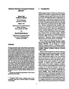
5. NUMERICAL RESULTS
The following diagrams present some results of our simulation runs. Graphs are shown for link loss probabilities of p : ,p : and p : . The tree height h that is given on the x axis includes the first hop from the sender to the top router (see fig. 3), so that the number of receivers (h?1) . The graphs show thus multicast is nR trees from 4 to 512 receivers. Note that the “end-toend” loss probability increases with the tree height because packet loss occurs independently in each router’s and receiver’s incoming queue.
= 0 001 = 0 010
0 050
=2
The FEC parameters are kept constant with a mesdata packets and a redundancy sage size of k of n ? k packets, so that a total loss of 4 packets can be compensated without the need for retransmissions.
= 12 =4
In the first graph series (fig. 4 through 6), the calculated capacity of the log server is compared to the actually needed log server capacity. The lower absolute capacity numbers in fig. 6 result from a lower packet sending rate (1 packet/sec instead of 10 packets/sec for the other graphs); this was necessary because of restrictions in the simulation environment.
1
packets that are lost in a row (derived analogously to m above), and tSR is the time a packet needs to traverse the tree from root to leaf. Assuming that s q, from which follows that k m, we get
=
= texpire = m � (�tgen + tBL max ) + 2tSR :
(13)
80 70 60 Calculated LS capacity
50 40
Max.LS search depth
30 20 10 0
We can now calculate the minimum number of data packets the log server must store:
texpire cLS = � tgen = m + k t�BLtmax + 2 �ttSR gen gen � � t BL max = m � 1 + �tgen + 2 �ttSRgen
p = 0.001 90
Number of packets
texpire = m � �tgen + k � tBL max + 2tSR (12) where �tgen is the (constant) interval of data transmission of the sender on channel P, k is (with a probability of 1 ? s) the maximum number of NAK
3
4
5
6
7
8
9
10
Height of tree
(14) (15) (16)
=
Fig. 4. Log Server capacity for p
= 0:001
D ESIGN
OF A
S CALABLE R ELIABLE M ULTICAST T RANSPORT P ROTOCOL data transmission. A solution would be to increase the amount of redundancy for the FEC encoding. Implementations of the protocol should contain dynamic adjustment of these parameters, depending on the number of NAKs seen by the log server.
p = 0.010 175 150 125 100
Calculated LS capacity Max.LS search
75 50
Numbe
p = 0.001 0.009 0.008 0.007
25
0.006 0
Ratio NAK/DATA
0.005 3
4
5
6
7
8
9
10
0.004
Height of tree
Total loss per receiver
0.003
Fig. 5. Log Server capacity for p
= 0:010
0.002 0.001 0 3
p = 0.050
4
5
7
8
9
10
Height of tree
90
Fig. 7. NAK/data and total loss for p
80
Number of packets
6
70 60 Calculated LS capacity
50 40
Max.LS search depth
30 20 10 0 3
4
5
6
7
8
9
10
Height of tree
Fig. 6. Log Server capacity for p
= 0:050
As can be seen, the log server is able to fulfill all retransmission requests in all cases. Furthermore, the storage capacity that is needed is approximately proportional to the logarithm of the number of receivers. In the case of high packet loss, the “safety margin” becomes very thin. A solution would be to increase the FEC redundancy. The increase in bandwidth usage by the additional FEC redundancy is at least partially compensated by the decreasing number of retransmissions. The second graph series (fig. 7 through 9) shows the ratio “NAKs seen at the log server” to “total number of data packets sent by the sender”, as well as the average total packet loss experienced by the receivers (i. e. the total percentage of packets that were lost somewhere on the way from the sender to the receiver). For networks with a high packet loss probability, the ratio NAK/data is very high. This high number of retransmissions implies higher latencies for the
= 0:001
p = 0.010 0.3 0.275 0.25 0.225 0.2 0.175 0.15 0.125 0.1 0.075 0.05 0.025 0
Ratio NAK/DATA Total loss per receiver
3
4
5
6
7
8
9
10
Height of tree
Fig. 8. NAK/data and total loss for p
= 0:010
p = 0.050 20 17.5 15 12.5
Ratio NAK/DATA
10
Total loss per receiver
7.5 5 2.5 0 3
4
5
6
7
8
9
10
Height of tree
Fig. 9. NAK/data and total loss for p
= 0:050
D ESIGN
OF A
S CALABLE R ELIABLE M ULTICAST T RANSPORT P ROTOCOL
6. CONCLUSIONS AND FURTHER WORK We have presented some thoughts on the design of a scalable, reliable, one-to-many multicast transport protocol. The basic ideas behind our proposal are establishing a homogeneous receiver group, the use of backlogging techniques to avoid NAK implosion, a combination of FEC and ARQ for ensuring reliability, and using two separate multicast group addresses for the original transmission and for retransmissions. Our simulation has shown that the protocol scales very well to a big number of receivers. Due to the use of FEC, the amount of retransmissions can be drastically decreased or even totally eliminated. This makes the protocol appli-
cable in fields where a feedback channel is very expensive or not available, e. g. satellite communications. Further research could be directed to the following areas: � optimizing retransmission handling, � studying the effect of dynamic adjustment of FEC parameters, � examining the use of a hierarchy of local retransmission servers, � building a framework for the multicast group management (“contract” management, subscription and connection management, etc.) , � implementing the protocol and testing it under “real world” conditions.
REFERENCES [1] Brian Neil Levine, “A comparison of known classes of reliable multicast protocols,” M.S. thesis, University of California, Santa Cruz, June 1996. [2] Brian Neil Levine, David B. Lavo, and J. J. Garcia-Luna-Aceves, “The case for reliable concurrent multicasting using shared ack trees,” Tech. Rep., Department of Computer Engineering, University of California, Santa Cruz, Sept. 1996. [3] Don Towsley and Jim Kurose, “A Comparison of Sender-Initiated and Receiver-Initiated Reliable Multicast Protocols,” Tech. Rep., Dept. of Electrical and Computer Engineering, University of Massachusetts, Amherst, Oct. 1996. [4] Harry Santoso and Serge Fdida, “An Efficient Error Control for Statistical Reliable Multicast,” Tech. Rep., Aug. 1993. [5] Matthias Grossglauser, “Optimal deterministic timeouts for reliable scalable multicast,” IEEE Journal on Selected Areas in Communications, vol. 15, no. 3, Apr. 1997. [6] J¨org Nonnenmacher, Martin Lacher, Matthias Jung, Ernst W. Biersack, and Georg Carle, “How bad is Reliable Multicast without Local Recovery,” Tech. Rep., Institut EURECOM, Sophia-Antipolis, France, Jan. 1998. [7] Sneha K. Kasera, Jim Kurose, and Don Towsley, “A comparison of server-based and receiver-based local recovery approaches for scalable reliable multicast,” Tech. Rep., Department of Computer Science, University of Massachusetts, Amherst, Nov. 1997. [8] Markus Hofmann, Torsten Braun, and Georg Carle, “Multicast communication in large scale networks,” in Proceedings of Third IEEE Workshop on High Performance Communication Subsystems (HPCS), Mystic, Connecticut, Aug. 1995. [9] Sneha K. Kasera, Jim Kurose, and Don Towsley, “Scalable Reliable Multicast Using Multiple Multicast Groups,” Tech. Rep., Department of Computer Science, University of Massachusetts, Feb. 1997. [10] Luigi Rizzo, “Effective erasure codes for reliable computer communication protocols,” ACM Computer Communication Review, vol. 27, no. 2, pp. 24–36, Apr. 1997. [11] Luigi Rizzo, “On the feasibility of software FEC,” Tech. Rep., Dip. di Ingegneria dell’Informazione, Universit`a di Pisa, Jan. 1997. [12] Luigi Rizzo and Lorenzo Vicisano, “A Reliable Multicast data Distribution Protocol based on software FEC techniques,” Tech. Rep., Dipartimento di Ingegneria dell’Informazione, Universit`a di Pisa and Department of Computer Science, University College, London, Apr. 1997. [13] J¨org Nonnenmacher and Ernst W. Biersack, “Reliable Multicast: Where to use FEC,” Tech. Rep., Corporate Communications Department, Institut EURECOM, Sophia-Antipolis, France, 1996. [14] Luigi Rizzo and Lorenzo Vicisano, “RMDP: an FEC-based Reliable Multicast protocol for wireless environments,” Mobile Computer and Communication Review, vol. 2, no. 2, Apr. 1998. [15] Bikash Sabata, Michael J. Brown, and Barbara A. Denny, “Transport Protocol for Reliable Multicast: TRM,” in International Conference on Networks, Orlando, Florida, Jan. 1996.
D ESIGN
OF A
S CALABLE R ELIABLE M ULTICAST T RANSPORT P ROTOCOL
[16] Sanjoy Paul, John C. Lin, and Supratik Bhattacharyya, “Reliable Multicast Transport Protocol (RMTP),” IEEE Journal on Selected Areas in Communications, special issue on Network Support for Multipoint Communication, 1996. [17] Brian Whetten, Todd Montgomery, and Simon Kaplan, “A high performance totally ordered multicast protocol,” Tech. Rep., University of California at Berkeley, West Virginia University, University of Illinois at Champaign-Urbana, 1994. [18] XTP Forum, Xpress Transport Protocol Specification – XTP Revision 4.0, XTP Forum, 1394 Greenworth Place, Santa Barbara, CA 93108, USA, Mar. 1995. [19] E. Braden, L. Zhang, S. Berson, S. Herzog, and S. Jamin, “Resource ReSerVation Protocol (RSVP) – Version 1 Functional Specification,” RFC 2205, Sept. 1997. [20] S. Deering, “Host Extensions for IP Multicasting,” RFC 1112, Aug. 1989. [21] J¨org Nonnenmacher and Ernst Biersack, “Performance Modelling of Reliable Multicast Transmission,” Tech. Rep., Institut EURECOM, Sophia-Antipolis, France, Dec. 1996.