Back to Programme
Back to Topic
Next Paper
ON THE PERFORMANCE OF MICRO LATTICE STRUCTURES AS CORE MATERIALS IN SANDWICH PANELS SUBJECT TO LOW VELOCITY IMPACT R. Mines*, S. Tsopanos, E. Shen, S. McKown, W. Cantwell, W. Brooks, C. Sutcliffe Department of Engineering, The Quadrangle, University of Liverpool, Liverpool, L69 3GH, UK *
[email protected]
SUMMARY Small sandwich panels have been manufactured with stainless steel and titanium alloy micro lattice cores produced by selective laser melting and with carbon epoxy skins. These panels have been subjected to drop weight loading from a steel hemisphere, and resultant damage has been quantified. Keywords: Micro lattice structures, sandwich panel, drop weight impact.
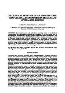
INTRODUCTION A manufacturing procedure has been developed at Liverpool, in which the selective laser melting (SLM) process is used to realise metallic micro lattice structures, which can then be used as core materials in sandwich structures [1,2]. For example, stainless steel 316L powder (with 30 microns diameter) can be selectively melted to produce body centred cubic (BCC) blocks of core material, with dimensions up to 200mm cubed. The cell size is typically 2.5mm. Figure 1 gives the BCC architecture and a picture of a 20mm cubed block used for compression testing. Reference [2] concerned a sustained effort to fully quantify manufacturing parameters and associated micro strut mechanical properties.
Figure 1: BCC Architecture and a realised SS316L 20mm cubed block
It has been shown that this stainless steel micro structure material has comparable uni axial compression specific stiffness and strength as compared with the aluminium foam, Alporas [3]. It has also been shown that this material fails in a stable manner in compression, tension and shear [4]. More recently, the selective laser melting process has been developed to realise exactly the same micro lattice structure but in the titanium alloy, Ti 6 4, which has x0.56 density, x0.55 stiffness and x4.3 strength as compared with stainless steel 316L. This material has the potential to be competitive with aluminium honeycomb for specific stiffness and strength [3]. As yet, the micro lattice geometry has not been optimized and there are a number of lattice configurations possible [4].
EXPERIMENTAL PROCEDURE
In the case of the work here, 100mm by 100mm by 20mm blocks, manufactured using SLM [2], were compression moulded with four ply plain weave carbon epoxy skins to form small panels. Figure 2(a) shows the hot press and Table 1 gives details of the carbon epoxy skins.
(a) Figure 2: (a) Hot Press for panels and (b) Core skin bond detail
(b)
Table 1: Skin material parameters [5].
Prepreg material
Plain weave Carbon fibre / epoxy matrix
Skin lay-up
Tensile modulus (8
Tensile strength (8
ply laminate)
ply laminate)
g/m2
GPa
MPa
410 +/-15
58
850
Areal density
4 ply - nominal thickness 1.1mm
Pressure was applied at approximately 1 bar, and a temperature of 120°C for approximately 2 hours. Careful control of the pressure was required to prevent yielding of the lattice core but was still high enough to bond the prepregs together. Figure 2(b) gives detail of the core skin bond. It can be seen that the micro lattice core has been forced into the skin. The fracture properties of this core skin bond line have been discussed elsewhere [6], and it has been shown that for static monotonic loading, the core skin bond strength is high. It should be noted that micro lattice nodes penetrate the skin, which may lead to reduced in plane compression strength for the skins. These panels were then placed on four hemispherical supports and subjected to impact from a 10mm diameter hemisphere attached to a drop weight machine (see Figure 3).
Figure 3: Panel supported in drop hammer rig with hemispherical impactor The impact mass was 0.88 kg, and the maximum impact velocity and energy were 6 m/s and 14 J, respectively. Tests were also carried out with the panel placed on a rigid surface (fully supported), in order to simulate local impact conditions. Force versus displacement data was obtained using a laser Doppler velocimeter and a high speed camera. Also, post impact test damage was quantitatively assessed. Dent depth was measured using a clock gauge.
STAINLESS STEEL MICRO LATTICE CORE RESULTS Figure 4 gives force – displacement data for the stainless steel cored four point support case for different impact energies. For the 6.6J case, the upper skin has already damaged and upper skin penetration is about to occur. For the 8.3J impact case, the impactor has penetrated into the core. Figure 5(a) gives cross sectional data for the fully supported panel after impact. It has been shown that impactor penetration for a given impact energy is similar between a fully supported and a four point supported panel [7]. Figure 5(b) gives damage for an Alporas cored panel, and shows that damage for a given energy is similar to the micro lattice case. Figure 6 summarises dent depth versus impact energy data for the fully supported case. From the four point support case, it has previously been shown that panel response is dominated by local effects [7]. From Figure 6 it can be seen that Alporas aluminium foam is comparable with BCC Stainless Steel, and that impact loading gives a lower dent depth for a given impact energy as compared with the static case. 1.2 1.1
8.3J impact energy
1.0
6.6J impact energy
0.9
9.8J impact energy
0.8
13J impact energy
Load, kN
0.7 0.6 0.5 0.4
6.6J
13J
0.3 0.2 8.3J
0.1
9.8J
0.0 0
1
2
3
4
5
6
7 8 9 10 11 Indenter displacment, mm
12
13
14
15
16
17
18
Figure 4: Load versus Indenter Displacement for various impact energies for stainless steel cored sandwich panel under four point support.
(a)
(b)
Figure 5: Sectioned fully supported panel (a) Steel micro lattice after 11.5J impact and (b) Alporas after 10J impact
Figure 6: Dent depths for given impact energies. Series 1-BCC, static full support, Series 2-aluminium foam, impact full support, Series 3- BCC, impact full support
Ti 6 4 MICRO LATTICE CORE RESULTS Similar drop weight tests were carried out with Ti 6 4 micro lattice cores [3]. Core configuration was exactly the same as for the stainless steel case, apart from the change in material. Figure 7 compares the compression block behaviour between the two materials. In Figure 7(c), stress is taken as applied load divided by initial block cross sectional area and strain is based on overall block crushed length. These measures ignore block expansion (See Figure 7(a)) and any strain localisation (See Figure 7(b)).
(a)
(b)
(c)
Figure 7(a) : SS316L block at 50% crush, 7(b) : Ti 6 4 block at 10% crush and 7(c) : Block compression stress strain data for SS316L, Ti 6 4 HIPed and non HIPed From this it can be seen that the Ti 6 4 block has x5 stiffness and x 5 strength as compared with Stainless Steel 316L. HIP refers to Hot Isostatic Processing. Ti 6 4 is a more complex material as compared with stainless steel, and some post manufacture heat treatment is required. In this case, a component is subjected to both elevated temperature and isostatic gas pressure in a high pressure containment vessel. The pressurizing gas most widely used is argon (no chemical reaction). Figures 7(a) and 7(b) show the different failure modes of lattice blocks – in the case of Ti 6 4, failure is localised giving rise to ‘shear banding’. As far as the drop weight loading of panels is concerned, Figure 8 and 9 compares Ti 6 4 results with SS316L cored panel results. In Figure 8, tested specimens were sectioned using a diamond saw. This caused some micro lattice damage. A number of specimens are in the process of being CT scanned, which will avoid this problem. From Figure 9, it can be seen that the Ti 6 4 core initates failure at higher loads, suggesting that sub critical behaviour for the Ti 6 4 case will be superior. Full skin perforation occurs at similar indenter displacements. Perforation loads are higher for the Ti 6 4 case, which means higher energy absorption to a given dent depth. From Figure 8, it can be seen that micro strut damage is much more fragmented for the Ti 6 4 case. Reference [7] discussed the perforation behaviour of SS316L micro lattice cored panels, and indentified the tensile behaviour of micro struts as being important during indentation and perforation. Figure 10 gives top views of Ti 6 4 and SS316L panels after impact. From the figure it can be seen that skin damage and deformation is more localised for the Ti 6 4 case. This suggests that panel repair after impact would be less extensive for the Ti 6 4 case. For the Ti 6 4 case (density = 170 kgm-3) , specific load to skin failure = 5.29 kNkg-1m3, specific maximum load = 10.0 kNkg-1m3 and specific energy to maximum load = 0.029MJkg-1m3. The corresponding figures for SS316L (density = 250kgm-3) are 2.0, 4.4, and 0.019, respectively.
(a)
(b) Figure 8: Comparison of damage for energies given in Figure 9. (a) Ti 6 4, four point support, Eimp = 10.2J and (b) SS316L fully supported Eimp = 13.6J
Figure 9: Comparison of load versus indenter displacement four point support, (a) Ti 6 4-10, Eimp = 10.2J, (b) Ti 6 4-3, Eimp = 20.4J, (c) SS316L, Eimp= 13J
(a)
(b) Figure 10: Comparison between upper skin deformation after impact, four point support (a) Ti 6 4, Eimp= 10.2J and (b) SS316L, Eimp= 8.3J
CONCLUSIONS
This work is a preliminary study of the perforation behaviour of small sandwich panels with SLM realised micro lattice SS316L and Ti 6 4 cores subject to low velocity drop weight loading. No attempt has been made to optimise the configuration of the cores, but core details have been selected for reproducibility and quality of manufacture [2]. Also, foreign object impact has concerned energies at which the skin suffers extensive damage and at which the core suffers perforation. Sub critical damage has not been addressed here, and for this case damage behaviour will be different. Foreign object impact failure loads are higher for the Ti 6 4 case as compared with SS316L, which suggests a reduced dent depth for a given impact energy for the former case. This issue will be clarified in future tests. Impact damage has been shown to be more localised for the Ti 6 4 core, and this is attributed to less ductility with the Ti 6 4 parent material. Again, this needs to be
clarified by completing micro strut tensile tests for Ti 6 4, in a manner similar to SS316L [2]. Mines [1] discusses the core properties required for controlling the foreign object impact performance of sandwich panels. The selective laser melted micro lattice structures discussed here provide the possibility of optimising such behaviour. As discussed in Tsopanos et al [2], the current SS316L structure can be characterised by: BCC/SS316L/140/500/200/2.5/cubic i.e. body centred cubic, stainless steel 316L, laser power = 140W, laser exposure time = 500 micro seconds, strut diameter = 200 microns, cell size = 2.5mm, and cubic unit cell. All these parameters can be changed to give different micro lattice properties. Tsopanos et al [2] showed that by changing laser power and laser exposure time, the strut diameter can be changed between 150 and 250 microns, and the BCC block stiffness and strength can be changed by factors of up to 6 times. Mines et al [4] have discussed the effect of changing micro structure geometry, e.g. BCC,Z or F2BCC, and cell size, 1mm to 4mm. The latter can be thought of as a parametric variation in strut aspect ratio. At the moment, this data has been developed mostly for block compression. Fairly obviously, as cell size reduces, the density, stiffness and strength increases – but we are interested in specific stiffness and strength properties. Results from this work have been inconclusive, and the work needs to be extended to panel perforation (as discussed here). Mines et al [3] and this paper have discussed the effect of going from BCC SS316L to BCC Ti 6 4. Hence, it can be concluded that there is further potential to improve micro lattice structures (within the limitations of the SLM manufacturing process [2]) which should give improved panel foreign object impact performance. A closer comparison with its main competitor (aluminium honeycomb) is also required. It should be noted that graded and three dimensional micro lattice structures are possible with the SLM process [1]. Also, other mechanical properties for these micro lattice structures need to be studied, e.g. core skin bond strength, fatigue performance, impact effects (inertia and strain rate) and detailed micro strut deformation and failure (in tension, compression and bending).
ACKNOWLEDGEMENTS The work described in this paper was supported by contracts: EPSRC/EP/C009525/1, EPSRC/EP/009398/1 and EU FP6 CELPACT.
References 1.
RAW Mines, On the characterisation of cellular materials used in sandwich construction, 2008, Strain, Vol 44 No 1, pp71-84
2.
S. Tsopanos, R.A.W. Mines , S. McKown, Y. Shen, W.J. Cantwell, W.J. Brooks and C.J. Sutcliffe, The influence of processing parameters on the mechanical properties of selectively laser melted stainless steel micro-lattice structures, submitted to the Journal of Manufacturing Science and Engineering, ASME.
3.
R A W Mines, Y Girard, V Fascio, On the development of conventional and micro lattice cellular metals as core materials in sandwich construction, Proc. SEICO 09 SAMPE European International Conference, 2009.
4.
RAW Mines, S McKown, WJ Cantwell, S Tsopanos, WJ Brooks, CJ Sutcliffe, On the progressive collapse of micro lattice structures, In mini symposium on Cellular Materials and Sandwich Construction ICEM 13, Alexandroupolis, Greece, July 2007, Paper Number 158
5.
EP121-C15-53 Data Sheet, Gurit GmbH, Kassel, Switzerland
6.
Y. Shen, S. McKown, S. Tsopanos, C.J. Sutcliffe, R. Mines and W.J. Cantwell, The fracture properties of lightweight sandwich structures based on lattice architectures, ICCS 8, Oporto, 2008
7.
R.A.W. Mines, S. McKown, S. Tsopanos, Y. Shen, W.J. Cantwell, W.J. Brooks and C. Sutcliffe, 2008, Local effects during indentation of fully supported sandwich panels with micro-lattice cores, Applied Mechanics and Materials, 1314, pp85-90. Back to Programme
Back to Topic
Next Paper