Abstract—We investigate the performance of orthogonal fre- quency division
multiplexing (OFDM)-based dual-hop amplify- and-forward (AF) relay networks in
...
This article has been accepted for inclusion in a future issue of this journal. Content is final as presented, with the exception of pagination. IEEE TRANSACTIONS ON COMMUNICATIONS, ACCEPTED FOR PUBLICATION
1
On the Performance of OFDM-Based Amplify-and-Forward Relay Networks in the Presence of Phase Noise Payam Rabiei, Student Member, IEEE, Won Namgoong, Senior Member IEEE, and Naofal Al-Dhahir, Fellow IEEE
Abstract—We investigate the performance of orthogonal frequency division multiplexing (OFDM)-based dual-hop amplifyand-forward (AF) relay networks in the presence of phase noise (PHN). We show that the use of an AF relay may not be beneficial compared to a direct transmission in the presence of PHN. Using outage probability analysis, an upper bound on the allowable PHN level is derived which ensures that the dualhop outperforms the direct transmission. To improve dual-hop transmission performance in the presence of PHN, we propose a reduced-complexity joint channel and PHN estimator using fullpilot OFDM symbols for AF relay transmission. The proposed approach achieves a lower mean squared error compared to the conventional channel estimator. In addition, we derive a joint data detection and PHN estimation scheme for comb-type data OFDM symbols by modifying the maximum ratio combining metric to account for the effect of PHN at the destination node. Index Terms—Amplify and forwards relay, phase noise, channel estimation, OFDM.
I. I NTRODUCTION
D
EPLOYING multiple antennas in user terminals to enhance the rate and reliability of wireless communication may not be practical due to cost and size constraints. Therefore, relay communication schemes using single-antenna transceivers have received considerable attention in recent years, following the pioneering work in [1], [2]. The relay node helps the source node transmit the information to the destination more reliably. One approach to achieve this goal is by re-transmitting a linearly-scaled version of the received signal from the source to the destination. Relaying protocols have been proposed for use in beyond-third-generation (B3G) and fourth generation (4G) systems [3]. The two most common relaying protocols are amplifyand-forward (AF) and decode-and-forward (DF) [4]. In the TDMA-based AF relay protocol considered in this paper, the source broadcasts the signal to the relay and the destination in the first hop (i.e. first transmission time slot). In the second hop, the relay amplifies the received signal and forwards it to the destination while the source is silent (see Fig.1). Since Paper approved by M. Juntti, the Editor for MIMO and Multiple-Access of the IEEE Communications Society. Manuscript received April 6, 2010; revised September 29, 2010. The authors are with the Department of Electrical Engineering, University of Texas at Dallas (e-mail: {pxr054100, namgoong, aldhahir}@utdallas.edu). This work was supported in part by the National Science Foundation (NSF) under contract CCF 07-33124. Digital Object Identifier 10.1109/TCOMM.2011.030411.100206
there is no collision between the received signals during the two consecutive hops at the destination, this transmission protocol maintains orthogonality at the expense of loss in spectral efficiency. In the IEEE 802.16j standard [5], orthogonal frequency division multiplexing (OFDM) is used in each time slot to combat frequency selectivity of the channel in each link. For coherent reception of OFDM signals, accurate phase information is required at the destination. A small phase drift at the output of the local oscillator at each node can significantly limit the overall system bit error rate (BER) performance due to loss of orthogonality among subcarriers. The effect of phase noise (PHN) on the OFDM signal is modeled in [6], [7], where PHN causes a rotation of each time-domain OFDM sample by a random phase drift. This effect can be modeled in the frequency domain by two terms: the common phase error (CPE), which is an identical phase rotation in all subcarriers and the inter-carrier interference (ICI), which is a result of the loss of orthogonality among subcarriers. A. Related Work Since the landmark work on relay systems in [8], [9], several practical transmission protocols were proposed in [1], [2], [4] along with analysis on their achievable rate and diversity order. The outage probability analysis for the AF relaying protocol was presented for Rayleigh flat fading in [10], [11] and Nakagami-𝑚 fading in [12], [13]. The effect of co-channel interference on the performance of relay systems was studied in [14], [15]. In [16]–[18], OFDM modulation was applied to combat frequency-selectivity of the relay channel. Channel estimation for OFDM-based relay networks was studied in [19]–[22]. Recently, [23] considered OFDM channel estimation in the presence of carrier frequency offset and provided performance analysis in terms of channel estimation mean squared error (MSE). B. Contributions of This Work In this paper, we study the effect of PHN on an OFDMbased AF relay network (see Fig. 1). PHN induces ICI at the relay node which can significantly degrade the BER performance of dual-hop compared to direct transmission. This issue becomes more pronounced as the number of relays increases at a fixed transmission rate. We characterize the performance of
c 2011 IEEE 0090-6778/11$25.00 ⃝
This article has been accepted for inclusion in a future issue of this journal. Content is final as presented, with the exception of pagination. 2
IEEE TRANSACTIONS ON COMMUNICATIONS, ACCEPTED FOR PUBLICATION
OFDM-based AF relay transmission using outage probability analysis. We show that the outage probability in the AF case is larger than the direct transmission case, unless the PHN level is below a certain threshold determined by the transmission rate, OFDM signal bandwidth, and the DFT size. This threshold is low and corresponds to realistic PHN levels. In addition, we propose a joint frequency-domain channel and PHN estimation scheme for AF relay transmission and show that the channel estimation MSE of the proposed joint estimator is less than the conventional method1. Furthermore, we propose a data detection scheme based on maximum ratio combining (MRC) which was shown to be optimum [25] for the AF protocol. We modify the MRC metric to take the effect of PHN into account. C. Outline and Notation In Section II, the system model is presented. Our proposed joint channel and PHN estimation scheme based on full-pilot OFDM symbols is described in Section III. In Section IV, joint data detection and PHN estimation based on comb-type data OFDM symbols is investigated. In Section V, outage performance is analyzed and numerical results are presented in Section VI. Conclusions are drawn in Section VII. Notation: The operators ℜ(⋅) and ℑ(⋅) are the real and imaginary parts of complex numbers, respectively. The operators (⋅)∗ , (⋅)𝑇 and (⋅)𝐻 denote the complex conjugate, transpose and the complex conjugate transpose operations, respectively. 𝐴¯𝑖 (𝑚, 𝑛) is the (𝑚, 𝑛) element of the time-domain matrix 𝐴¯𝑖 and 𝑎 ¯𝑖 (𝑛) is the 𝑛th entry of the time-domain vector 𝑎 ¯𝑖 at the 𝑖th transmission time slot, respectively. Frequency-domain matrices and vectors are denoted in boldface as in 𝑨 and 𝒂, respectively. II. S YSTEM M ODEL The system considered in this paper (see Fig. 1) consists of one source, one destination, and one relay node (𝑛𝑅 = 1). The extension of this study to multiple relays is straightforward if an orthogonal transmission protocol is used. The transmission protocol assumed is orthogonal TDMA-based AF over two time slots2 . To combat the channel’s frequencyselectivity, OFDM modulation is used. Transmission consists of two stages as in IEEE 802.16j. In the first stage, full-pilot OFDM symbols are transmitted to facilitate estimation of the frequency-selective channels between nodes. In the second stage, comb-type pilot-data-multiplexed OFDM symbols are transmitted. PHN is assumed to be present whenever a local oscillator (LO) is used. PHN varies across all transmission time slots from one OFDM sample to the next. In the first time slot, the time-domain received vector 𝑦¯𝑑,1 after down-conversion, sampling, and cyclic prefix (CP) removal at the destination is given by ¯𝑑,1 𝐻 ¯ 𝑠𝑑 𝐸 ¯𝑠,1 𝑥¯𝑠,1 + 𝑧¯𝑑,1 𝑦¯𝑑,1 = 𝐸 1 By
(1)
conventional channel estimation, we mean ignoring PHN as in [24]. transmission rate is defined as 𝑅 = 𝑇1 log2 ∣𝐶∣ where 𝑇𝑡 is the 𝑡 number of transmission time slots as 𝑇𝑡 = 𝑛𝑅 + 1 and ∣𝐶∣ is the cardinality of the signal constellation used. For example, using 16QAM with 𝑛𝑅 = 1 we have 𝑅 = 2. For fair comparison in terms of transmission rate, we have to transmit 4QAM or 2 bits per time slot in direct transmission mode as well. 2 The
¯𝑑,1 are 𝑁 ×𝑁 diagonal matrices representing where 𝐸¯𝑠,1 and 𝐸 the PHN process at the source and destination in the first time slot, respectively. The PHN process can be modeled as a ¯𝑘,𝑚 (𝑛, 𝑛) = exp(𝑗 𝜃¯𝑘,𝑚 (𝑛)) for the small phase drift i.e. 𝐸 𝑚th transmission time slot, 𝑘 ∈ {𝑠, 𝑟, 𝑑} and 𝜃¯𝑘,𝑚 (𝑛) = 𝜃¯𝑘,𝑚 (𝑛 − 1) + 𝜖, where 𝜖 is a Gaussian random variable with zero mean and variance 2𝜋𝛽𝑇𝑠 , where 𝑇𝑠 is the sampling interval and 𝛽 is the 3dB PHN bandwidth. This is the Wiener model for the PHN process which is accurate for free running ¯ 𝑠𝑑 is the 𝑁 × 𝑁 time-domain circulant oscillators [26]. 𝐻 channel matrix constructed by column-wise circularly shifting ¯ 𝑠𝑑 with memory the channel impulse response (CIR) vector ℎ 𝜈, which is assumed to be less than the CP length 𝑐. 𝑁 is the DFT size, 𝑥¯𝑠,1 is the transmitted OFDM symbol from the source at the first time slot, and 𝑧¯𝑑,1 is the noise vector at the destination which is assumed to be additive white Gaussian noise (AWGN) with zero mean and variance 𝜎𝑧2 . In addition to the destination node, the transmitted OFDM symbol in the first time slot is received at the relay node ¯ 𝑠𝑟 . The time-domain received vector at the relay through link ℎ 𝑦¯𝑟,1 is given by 𝑦¯𝑟,1 =
√ ¯ 𝑠𝑟 𝐸 ¯𝑠,1 𝑥¯𝑠,1 + 𝑧¯𝑟,1 𝑔𝑠𝑟 𝐸¯𝑟,1 𝐻
(2)
where 𝑔𝑠𝑟 = (𝑑𝑠𝑑 /𝑑𝑠𝑟 )𝛾 is the large-scale fading gain since the distance between the relay and the source is smaller than the distance between the source and the destination (see Fig. 1). 𝑑𝑠𝑑 and 𝑑𝑠𝑟 are the physical distances from 𝑠 → 𝑑 and 𝑠 → 𝑟, respectively, 𝛾 is the large-scale fading exponent, and ¯𝑟,1 𝑧¯𝑟,1 is the AWGN vector at the relay. The diagonal matrix 𝐸 is the PHN matrix at the receive chain (i.e. down-conversion) of the relay front-end which is different from the transmit chain (i.e. up-conversion) PHN matrix at the second time slot ¯𝑟,2 (see Fig. 1). denoted by 𝐸 In the second time slot, the source remains silent and the relay forwards its received signal to the destination. Specifically, in the AF mode considered in this paper, the relay amplifies the received signal and forwards it to the destination. The received signal at the destination in the second time slot is √
𝑦¯𝑑,2
=
𝑔𝑟𝑑 √
= √ =
E[∣¯ 𝑥𝑠,1 ∣2 ] ¯ ¯ ¯ 𝐸𝑑,2 𝐻𝑟𝑑 𝐸𝑟,2 𝑦¯𝑟,1 + 𝑧¯𝑑,2 E[∣¯ 𝑦𝑟,1 ∣2 ]
(3)
𝑔𝑟𝑑 ℰ𝑥 ¯𝑑,2 𝐻 ¯ 𝑟𝑑 𝐸 ¯𝑟,2 𝑦¯𝑟,1 + 𝑧¯𝑑,2 𝐸 𝑔𝑠𝑟 ℰ𝑥 𝜎ℎ2 + 𝜎𝑧2 𝑔𝑟𝑑 𝑔𝑠𝑟 ℰ𝑥 ¯ ¯ ¯ ¯ ¯ ¯ ¯𝑠,1 + 𝑧¯eff,2 𝐸𝑑,2 𝐻𝑟𝑑 𝐸𝑟,2 𝐸𝑟,1 𝐻𝑠𝑟 𝐸𝑠,1 𝑥 𝑔𝑠𝑟 ℰ𝑥 𝜎ℎ2 + 𝜎𝑧2
¯ 𝑠𝑟 ∣2 ] is where E[⋅] is the expectation operation, 𝜎ℎ2 = E[∣ℎ 3 the instantaneous squared-norm of the CIR vector , 𝑔𝑟𝑑 = (𝑑𝑠𝑑 /𝑑𝑟𝑑 )𝛾 , 𝑑𝑟𝑑 is the distance from 𝑟 → 𝑑, 𝑧¯𝑑,2 is ¯𝑑,2 is the PHN matrix at the AWGN at the destination, 𝐸 ¯ 𝑟𝑑 is the timedestination in the second time slot and 𝐻 domain circulant channel matrix from relay to destination. Moreover, in (3), the relay normalizes 𝑦¯𝑟,1 by its power (in baseband and after the down-conversion) and amplifies it by ℰ𝑥 = E[∣¯ 𝑥𝑠,1 ∣2 ] to ensure that its transmit power is the 3 Note that the CIR variance is assumed to be 𝜎 2 for all links i.e. 𝑠 → 𝑟, ℎ 𝑠 → 𝑑 and 𝑟 → 𝑑.
This article has been accepted for inclusion in a future issue of this journal. Content is final as presented, with the exception of pagination. RABIEI et al.: ON THE PERFORMANCE OF OFDM-BASED AMPLIFY-AND-FORWARD RELAY NETWORKS IN THE PRESENCE OF PHASE NOISE
same as the √ source. In (3), the effective noise at the destina¯𝑑,2 𝐻 ¯ 𝑟𝑑 𝐸 ¯𝑟,2 𝑧¯𝑟,1 + 𝑧¯𝑑,2 . tion, 𝑧¯eff,2 = 𝑔𝑟𝑑 ℰ𝑥 /(𝑔𝑠𝑟 𝜎ℎ2 ℰ𝑥 + 𝜎𝑧2 )𝐸 Transforming 𝑦¯𝑑,1 and 𝑦¯𝑑,2 from (1) and (3) to the frequency domain we have 𝒚 𝑑,1 = 𝑄¯ 𝑦𝑑,1 = 𝑷 𝑑,1 𝑯 𝑠𝑑 𝑷 𝑠,1 𝒙𝑠,1 + 𝒛 𝑑,1 𝒚 𝑑,2 = 𝑄¯ 𝑦𝑑,2 √ 𝑔𝑟𝑑 𝑔𝑠𝑟 ℰ𝑥 = 𝑷 𝑑,2 𝑯 𝑟𝑑 𝑷 𝑟 𝑯 𝑠𝑟 𝑷 𝑠,1 𝒙𝑠,1 + 𝒛 eff,2 𝑔𝑠𝑟 ℰ𝑥 𝜎ℎ2 + 𝜎𝑧2 (4) where 𝑯 𝑠𝑑 , 𝑯 𝑠𝑟 and 𝑯 𝑟𝑑 are diagonal frequency-domain channel matrices, 𝑄 is the DFT matrix and 𝑷 𝑟 = 𝑷 𝑟,1 𝑷 𝑟,2 is the effective frequency-domain PHN matrix during up- and down-conversion at the relay which has a 3 dB bandwidth of 𝛽𝑟 = 𝛽𝑟,1 + 𝛽𝑟,2 . All the frequency-domain PHN matrices i.e. 𝑷 𝑖 are functions of 𝛽𝑖 for 𝑖 ∈ {𝑠, 𝑟, 𝑑} and are circulant. Furthermore, as 𝛽𝑖 𝑇𝑠 decreases, the off-diagonal elements of 𝑷 𝑖 become smaller and, therefore, 𝑷 𝑖 has a circulant and approximately-banded (CAB) structure. Using the results in [27], for 𝛽𝑖 𝑇𝑠 ≪ 1 and assuming a slow-fading channel, (4) can be approximated as 𝒚 𝑑,1 ≈ 𝑷 𝑠𝑑,1 𝑯 𝑠𝑑 𝒙𝑠,1 + 𝒛 𝑑,1 √ 𝑔𝑟𝑑 𝑔𝑠𝑟 ℰ𝑥 𝒚 𝑑,2 ≈ 𝑷 𝑠𝑟𝑑,2 𝑯 𝑟𝑑 𝑯 𝑠𝑟 𝒙𝑠,1 + 𝒛 eff,2 𝑔𝑠𝑟 ℰ𝑥 𝜎ℎ2 + 𝜎𝑧2
(5)
where 𝑷 𝑠𝑑,1 and 𝑷 𝑠𝑟𝑑,2 are the effective frequency-domain PHN matrices during the first and the second hops from 𝑠 → 𝑑 and from 𝑠 → 𝑟 → 𝑑, respectively. The effective 3 dB bandwidths of these two effective PHN processes are given by 𝛽𝑠𝑑 := 𝛽𝑠 + 𝛽𝑑 ; 𝛽𝑠𝑟𝑑 := 𝛽𝑠 + 𝛽𝑟 + 𝛽𝑑 (6) The approximate signal model in (5) simplifies the receiver design significantly. Therefore, in this paper, we use the approximate signal model in (5) for channel estimation, data detection, and performance analysis. The complete model in (4) is used in simulations and to validate the assumptions made in our analysis. As shown later, the approximation in (5) is accurate for realistic PHN values. III. C HANNEL E STIMATION Effective channel estimation schemes in the presence of PHN are presented in this section. Although only one relay is assumed (i.e., 𝑛𝑅 = 1), generalization to multiple relays is straightforward. A. Channel Estimation for AF Mode In the AF mode, channel estimation for 𝑠 → 𝑟 → 𝑑 link is performed independent of the 𝑠 → 𝑑 link since the assumed transmission protocol is orthogonal. Based on (5), the leastsquares (LS) estimate of the CIR’s can be written as ˆ ¯ 𝑠𝑑 = 1 𝑊 𝐻 𝑿 𝐻 𝑷 𝐻 𝒚 ℎ ℰ𝑥 𝑠𝑑 𝑠,1 𝑠𝑑,1 𝑑,1 (7) 1 𝐻 𝐻 ˆ ¯ 𝑊𝑠𝑟𝑑 𝑿𝐻 ℎ 𝑠𝑟𝑑 = 𝑠,1 𝑷 𝑠𝑟𝑑,2 𝒚 𝑑,2 𝜇ℰ𝑥 where 𝑿 𝑠,1 is a diagonal matrix constructed from 𝒙𝑠,1 , 𝑊𝑠𝑑 and 𝑊𝑠𝑟𝑑 are submatrices of 𝑄 with size 𝑁 × 𝜈 and 𝑁 ×
3
(2𝜈 − 1), respectively, constructed by choosing the first 𝜈 or ¯ 𝑠𝑟𝑑 = ℎ ¯ 𝑠𝑟 ⊗ ℎ ¯ 𝑟𝑑 is the 2𝜈 − 1 columns of 𝑄. Moreover, ℎ convolution of the link CIR’s from 𝑠 → 𝑟 and from 𝑟 → 𝑑 with length 2𝜈 − 1. 𝜇 in (7) is the scaling factor which at high signal-to-noise ratios (SNR) becomes √ √ 𝑔𝑟𝑑 𝑔𝑠𝑟 ℰ𝑥 𝑔𝑟𝑑 (8) 𝜇= ≗ 𝑔𝑠𝑟 𝜎ℎ2 ℰ𝑥 + 𝜎𝑧2 𝜎ℎ2 where ≗ denotes asymptotic equivalence at high SNR. The LS channel estimates in (7) are dependent on the effective PHN matrices. Since PHN is a low pass process it can be characterized by few spectral components. In [28], the PHN vector estimate is derived as a solution to the following constrained quadratic form maximization ˆ𝑇𝑠𝑑,1 = arg max 𝒑𝑠𝑑,1 𝑴 𝑠𝑑 𝒑𝐻 𝒑 𝑠𝑑,1 𝒑𝑠𝑑,1
ˆ𝑇𝑠𝑟𝑑,2 𝒑
= arg max 𝒑𝑠𝑟𝑑,2 𝑴 𝑠𝑟𝑑 𝒑𝐻 𝑠𝑟𝑑,2
(9)
𝒑𝑠𝑟𝑑,2
where 𝒑𝑠𝑑,1 and 𝒑𝑠𝑟𝑑,2 are the first rows of the effective CAB matrices 𝑷 𝑠𝑑,1 and 𝑷 𝑠𝑟𝑑,2 , respectively. Further𝐻 𝐻 more, 𝑴 𝑠𝑑 = 𝒀 𝐻 𝑑,1 𝑿 𝑠,1 𝑉𝑠𝑑 𝑉𝑠𝑑 𝑿 𝑠,1 𝒀 𝑑,1 and 𝑴 𝑠𝑟𝑑 = 𝐻 𝐻 𝒀𝐻 𝑑,2 𝑿 𝑠,1 𝑉𝑠𝑟𝑑 𝑉𝑠𝑟𝑑 𝑿 𝑠,1 𝒀 𝑑,2 , 𝑉𝑠𝑑 and 𝑉𝑠𝑟𝑑 are 𝑁 × (𝑁 − 𝜈) and 𝑁 × (𝑁 − 2𝜈 + 1) submatrices consisting of the last (𝑁 − 𝜈) and (𝑁 − 2𝜈 + 1) columns of 𝑄, respectively. 𝒀 𝑑,1 and 𝒀 𝑑,2 are circulant matrices constructed from the received signal vectors 𝒚 𝑑,1 and 𝒚 𝑑,2 , respectively. Our objective is to maximize the quadratic forms in (9) subject to the constraint that all time-domain PHN elements are small, i.e. they are all ¯ of the form of 𝑒𝑗 𝜃𝑘,𝑚 (𝑛) for 𝑘 ∈ {𝑠, 𝑟, 𝑑} and 𝑚th transmission ¯ time slot. For small PHN, 𝑒𝑗 𝜃𝑘,𝑚 (𝑛) ≈ 1 + 𝑗 𝜃¯𝑘,𝑚 (𝑛). This approximate time-domain constraint facilitates a closed-form solution for (9). The frequency-domain interpretation of this constraint is that the real part of the first element of either 𝒑1 or 𝒑2 is one. From [28], the solution to (9) is given by 𝒑𝑠𝑟𝑑,2 )𝑇 = 𝜆2 𝑺 2 𝒆𝑇 ℑ(ˆ 𝒑𝑠𝑑,1 )𝑇 = 𝜆1 𝑺 1 𝒆𝑇 ; ℑ(ˆ 𝑇 𝑇 ℜ(ˆ 𝒑𝑠𝑑,1 )𝑇 = 𝜆1 Γ−1 1 (Λ1 𝑺 1 + 𝑰)𝒆 𝑇
ℜ(ˆ 𝒑𝑠𝑟𝑑,2 ) =
𝑇 𝜆2 Γ−1 2 (Λ2 𝑺 2
+ 𝑰)𝒆
(10)
𝑇
where Γ1 , Γ2 , Λ1 and Λ2 are the real and imaginary parts of the Hermitian matrices 𝑴 𝑠𝑑 and 𝑴 𝑠𝑟𝑑 , respectively. In (10), 𝜆1 and 𝜆2 are Lagrange multipliers which are given by 𝜆1 = 𝜆2 =
1 𝑇 𝒆[Γ−1 1 Λ1 𝑺 1
𝑇 + Γ−1 1 ]𝒆
𝑇 𝒆[Γ−1 2 Λ2 𝑺 2
𝑇 Γ−1 2 ]𝒆
1
+
2 −1 −1 where 𝑺 1 = [𝑰 + (Γ−1 Γ1 Λ1 Γ−1 1 Λ1 ) ] 1 −1 −1 2 −1 −1 (Γ2 Λ2 ) ] Γ2 Λ2 Γ2 and 𝒆 is a 1 × 𝑁
(11)
and 𝑺 2 = [𝑰 + row vector with first element equal to one and the other elements equal to zero. The complexity of the above estimator can be reduced by considering only the most significant elements of 𝒑𝑠𝑑,1 and 𝒑𝑠𝑟𝑑,2 . Based on the analysis in [6], [26], [29], the PHN process can be modeled as a low-pass process and, therefore, the PHN vector can be well approximated by estimating its 𝐿 + 1 elements only, i.e. 𝒑𝑠𝑑,1 (𝑁 − 𝐿/2), ⋅ ⋅ ⋅ , 𝒑𝑠𝑑,1 (0), ⋅ ⋅ ⋅ , 𝒑𝑠𝑑,1 (𝐿/2) and 𝒑𝑠𝑟𝑑,2 (𝑁 −𝐿/2), ⋅ ⋅ ⋅ , 𝒑𝑠𝑟𝑑,2 (0), ⋅ ⋅ ⋅ , 𝒑𝑠𝑟𝑑,2 (𝐿/2). As a result,
This article has been accepted for inclusion in a future issue of this journal. Content is final as presented, with the exception of pagination. 4
IEEE TRANSACTIONS ON COMMUNICATIONS, ACCEPTED FOR PUBLICATION
all matrices involved in the estimator of (10) can be reduced in size accordingly. The remaining PHN spectral components are set to zero, since they are in fact very small quantities. After estimating the real and imaginary parts of the PHN vector in the frequency domain, the CAB matrices 𝑷 𝑠𝑑,1 and 𝑷 𝑠𝑟𝑑,2 are constructed and substituted back into (7) to compute the channel estimates. Note that the PHN solutions in (10) are independent of the channel; hence, no iterations are needed in the joint channel and PHN estimation process. In summary, our proposed joint channel and PHN estimation scheme consists of two steps. In the first step, 𝐿 + 1 PHN spectral elements are estimated using (10). In the second step, the estimated PHN matrices are used in (7) to compute the LS channel estimate. B. Channel Estimation in Direct Transmission ¯ 𝑠𝑑 without relay assisFor direct transmission through ℎ ¯ 𝑠𝑑 is estimated twice across two transmission time tance, ℎ slots4 then averaged out. Specifically, from (1) we have ˆ ˆ𝐻 𝒚 ¯ 𝑠𝑑,1 = 1 𝑊 𝐻 𝑿 𝐻 𝑷 ℎ ℰ𝑥 𝑠𝑑 𝑠,1 𝑠𝑑,1 𝑑,1 1 𝐻 𝐻 ˆ𝐻 ˆ ¯ 𝑊 𝑿 𝑷 𝒚 ℎ 𝑠𝑑,2 = ℰ𝑥 𝑠𝑑 𝑠,2 𝑠𝑑,2 𝑑,2
(12)
ˆ 𝑠𝑑,2 are the estimated effective frequencyˆ 𝑠𝑑,1 and 𝑷 where 𝑷 domain PHN matrices during the first and the second transmission time slots, respectively, using the method described in the previous subsection. Finally, the source to destination ¯ 𝑠𝑑 = (ℎ ¯ 𝑠𝑑,1 + ℎ ¯ 𝑠𝑑,2 )/2. channel estimate is given by ℎ IV. C OMB -T YPE PHN C OMPENSATION AND DATA D ETECTION
where ∗
ˆ
ˆ (𝑘)𝒚 (𝑘) 𝒂1 (𝑘) = 𝑒−𝑗 𝜃1 𝒉 𝑠𝑑 𝑑,1 1 −𝑗 𝜃ˆ2 ˆ ∗ 𝒉𝑠𝑟𝑑 (𝑘)𝒚 𝑑,2 (𝑘) 𝒂2 (𝑘) = 𝑒 𝜇
The MRC metric in (14) uses the CPE estimate in each transmission time slot to compensate for the constant signal constellation rotation before data detection. It has been shown in [25] that MRC achieves the maximum likelihood (ML) performance of the AF relay mode assuming no PHN. B. SINR Analysis In this subsection, SINR expressions for direct and AF transmission modes are derived which will be used in the next section to compute the corresponding outage probabilities. Using the signal model in (5), the direct transmission mode received signal is decomposed into the desired signal term and the interference plus noise term as 𝒚 𝑑,1 ≈ 𝑯 𝑠𝑑 𝒙𝑠,1 + (𝑷 𝑠𝑑,1 − 𝑰 𝑁 )𝑯 𝑠𝑑 𝒙𝑠,1 + 𝒛 𝑑,1 where 𝑰 𝑁 is the identity matrix of size 𝑁 ×𝑁 . Therefore, assuming that the CPE term has been compensated for, the instantaneous SINR for the 𝑘th subcarrier conditioned on the channel knowledge can be written as 𝝆Dir (𝑘) =
ℰ𝑥 ∣𝒉𝑠𝑑 (𝑘)∣2 2 𝑁 −1 ∑ ℰ𝑥 𝒑𝑠𝑑,1 (𝑘 − 𝑞)𝒉𝑠𝑑 (𝑞) + 𝜎𝑧2 𝑞=0,𝑞∕=𝑘
∣𝒉𝑠𝑑 (𝑘)∣2 ≥ 𝑁 −1 ∑ (1 − 𝜎𝑝2 ) ∣𝒉𝑠𝑑 (𝑞)∣2 + 𝜎𝑧2 /ℰ𝑥
The lower bound in (16), which makes the analysis tractable is derived using the Cauchy-Schwartz inequality as � �2 � 𝑁−1 � 𝑁−1 𝑁−1 ∑ ∑ � ∑ � � � ≤ 𝒑 (𝑘 − 𝑞)𝒉 (𝑞) ∣𝒑𝑠𝑑,1 (𝑛)∣2 ∣𝒉𝑠𝑑 (𝑚)∣2 𝑠𝑑 𝑠𝑑,1 � � �𝑞=0,𝑞∕=𝑘 � 𝑛=1 𝑚=1 = (1 − 𝜎𝑝2 )
Ignoring ICI in data transmission stage, the CPE angle estimates of the effective PHN in AF mode are given by ( ) ∑ ∗ ∗ ˆ ˆ 𝜃1 = angle 𝒚 (𝑘)𝒉 (𝑘)𝒙 (𝑘) ( 𝜃ˆ2 = angle
∑
𝑠𝑑
𝑁−1 ∑ 𝑚=1
A. CPE Estimation and MRC Detector
𝑑,1
𝑠,1
)
(16)
𝑞=0,𝑞∕=𝑘
In this section, using equi-distant pilot tones placed in a comb-type data OFDM symbol, the CPE of the effective PHN at the receiver is estimated. These pilot tones and the estimated CIR vector from the preamble transmission stage are used to compute the CPE term. Based on the CPE and the channel estimates, a modified MRC metric is computed.
𝑘∈𝒫
(15)
(13)
ˆ ∗ (𝑘)𝒙∗ (𝑘) 𝒚 𝑑,2 (𝑘)𝒉 𝑠,2 𝑠𝑟𝑑
𝑘∈𝒫
where 𝒫 is the set of OFDM subcarrier indices which includes the pilot positions. In the AF mode, the CPE is compensated over two time slots and the data is detected using the following MRC metric 𝒂1 (𝑘) + 𝒂2 (𝑘) ˆ 𝑠,1 (𝑘) = 𝒙 (14) ˆ ˆ 𝑠𝑟𝑑 (𝑘)∣2 ∣𝒉𝑠𝑑 (𝑘)∣2 + ∣𝒉 4 For fair comparison with the AF mode, channel estimation is performed over 𝑛𝑅 + 1 time slots where 𝑛𝑅 is the number of relays.
∣𝒉𝑠𝑑 (𝑚)∣2 (17)
The second line ∑ in (17) follows since the PHN matrix is 𝑁 −1 2 orthonormal i.e. 𝑘=0 ∣𝒑𝑠𝑑,1 (𝑘)∣ = 1 therefore, we have ∑𝑁 −1 2 2 𝑘=1 ∣𝒑𝑠𝑑,1 (𝑘)∣ = 1 − ∣𝒑𝑠𝑑,1 (0)∣ . The norm-squared of 2 the CPE term i.e. ∣𝒑𝑠𝑑,1 (0)∣ is replaced by the variance 𝜎𝑝2 = E[∣𝒑𝑠𝑑,1 (0)∣2 ]. The variance of the CPE term can be com∑𝑁 −1 ¯ ¯ puted by noting that 𝒑𝑠𝑑,1 (0) = 1/𝑁 𝑞=0 𝑒𝑗 𝜃𝑠,1 (𝑞) 𝑒𝑗 𝜃𝑑,1 (𝑞) . Therefore ∫ 𝑁 −1 𝑁 −1 ∫ 1 ∑ ∑ ∞ ∞ 𝑗𝑥 𝜎𝑝2 = 2 𝑒 𝑓𝑋 (𝑥)𝑒𝑗𝑦 𝑓𝑌 (𝑦)𝑑𝑥𝑑𝑦 (18) 𝑁 −∞ −∞ 𝑛=0 𝑘=0
where we define 𝑥 := 𝜃¯𝑠,1 (𝑘)− 𝜃¯𝑠,1 (𝑛), 𝑦 := 𝜃¯𝑑,1 (𝑘)− 𝜃¯𝑑,1 (𝑛), 𝑓𝑋 = 𝒩 (0, 2𝜋𝛽𝑠 𝑇𝑠 ∣𝑛 − 𝑘∣) and 𝑓𝑌 (𝑦) = 𝒩 (0, 2𝜋𝛽𝑑 𝑇𝑠 ∣𝑛 − 𝑘∣). Evaluating the integrals and computing the summations using the Taylor expansion we get [30] 𝜎𝑝2 = 1 −
𝜋𝛽𝑠𝑑 𝑇𝑠 3
(19)
This article has been accepted for inclusion in a future issue of this journal. Content is final as presented, with the exception of pagination. RABIEI et al.: ON THE PERFORMANCE OF OFDM-BASED AMPLIFY-AND-FORWARD RELAY NETWORKS IN THE PRESENCE OF PHASE NOISE
where 𝛽𝑠𝑑 is defined in (6). Using (19) and (16) we get 𝝆Dir (𝑘) ≥
𝜋𝛽𝑠𝑑 𝑇𝑠 3
∣𝒉𝑠𝑑 (𝑘)∣2 𝑁 −1 ∑ 𝜎2 ∣𝒉𝑠𝑑 (𝑞)∣2 + 𝑧 ℰ𝑥
Proof:
(20)
𝑞=0,𝑞∕=𝑘
∑𝑁 −1 In (20), ∣𝒉𝑠𝑑 (𝑘)∣2 and 𝑞=0,𝑞∕=𝑘 ∣𝒉𝑠𝑑 (𝑞)∣2 are exponential and Gamma distributed random variables which are dependent. For the AF mode, since the destination performs MRC over two time slots, the SINR at the 𝑘th subcarrier from (5) can be written as 𝝆AF (𝑘) = 𝝆Dir (𝑘) + 𝝆Relay (𝑘)
(21)
where 𝝆Dir (𝑘) is the same as (20) and 𝝆Relay (𝑘) is given by 𝝆Relay (𝑘) =
𝝆𝑠𝑟 (𝑘)𝝆𝑟𝑑 (𝑘) ≤ min [𝝆𝑠𝑟 (𝑘), 𝝆𝑟𝑑 (𝑘)] 𝝆𝑠𝑟 (𝑘) + 𝝆𝑟𝑑 (𝑘) + 1 (22)
𝑎𝑋 < 𝑢) 𝐹𝑈 (𝑢, 𝑎, 𝑏, 𝑐) = Pr( 𝑏𝑌 ∫ ∞ +𝑐 𝑏𝑦𝑢 + 𝑐𝑢 = ∣𝑌 = 𝑦)𝑓𝑌 (𝑦)𝑑𝑦 Pr(𝑋 < 𝑎 0 ∫ ∞ ∫ (𝑏𝑦𝑢+𝑐𝑢)/𝑎 𝑓𝑋 (𝑥)𝑓𝑌 (𝑦)𝑑𝑥𝑑𝑦 = 0
0
(25)
Carrying out the integration using the PDFs described in the Lemma, the CDF in (24) is derived. As a figure of merit for the performance of an OFDM communication system, we compute the probability that the 𝑘th subcarrier does not support a given rate 𝑃Dir (𝑅) = Pr(log2 (1 + 𝝆Dir (𝑘)) < 𝑅) = Pr(𝝆Dir (𝑘) < 2𝑅 − 1) 𝑋 < 2𝑅 − 1) ≤ Pr( 𝑎𝑌 + 𝑏 ∫ ∞ ∫ (2𝑅 −1)(𝑎𝑦+𝑏) = 𝑓𝑋,𝑌 (𝑥, 𝑦)𝑑𝑥𝑑𝑦 0
0
≤ 𝐹𝑈 (2𝑅 − 1, 1, 𝑎, 𝑏)
where 𝑔𝑠𝑟 ∣𝒉𝑠𝑟 (𝑘)∣2 𝝆𝑠𝑟 (𝑘) ≥ 𝑁 −1 𝜋(𝛽𝑟,1 + 𝛽𝑠 )𝑇𝑠 ∑ 𝜎2 𝑔𝑠𝑟 ∣𝒉𝑠𝑟 (𝑞)∣2 + 𝑧 3 ℰ𝑥 𝑞=0,𝑞∕=𝑘
𝑔𝑟𝑑∣𝒉𝑟𝑑 (𝑘)∣2 𝝆𝑟𝑑 (𝑘) ≥ 𝑁 −1 𝜋(𝛽𝑟,2 + 𝛽𝑑 )𝑇𝑠 ∑ 𝜎2 𝑔𝑟𝑑 ∣𝒉𝑟𝑑 (𝑞)∣2 + 𝑧 3 ℰ𝑥
5
(26) ∑𝑁 −1
(23)
𝑞=0,𝑞∕=𝑘
are the SINR expressions for the source to relay and relay to destination links, respectively. The upper bound in (22) is much looser compared to lower bounds in (23). Therefore, the overall bound on 𝝆AF (𝑘) is dominated by (22) as 𝝆AF (𝑘) ≤ 𝝆Dir (𝑘) + min[𝝆𝑠𝑟 (𝑘), 𝝆𝑟𝑑 (𝑘)]. V. P ERFORMANCE A NALYSIS In this section, we analyze the outage probability of the AF and direct transmission modes in the presence of PHN. Since a lower bound is derived for the direct mode SINR and an upper bound is derived for AF mode SINR, the corresponding outage probabilities are sandwiched between the analytical outage probabilities. This provides an upper bound on the PHN level at which the AF mode outperforms the direct mode. A. Outage Probability for the Direct Mode Lemma: Let 𝑈 = 𝑎𝑋/(𝑏𝑌 + 𝑐), where 𝑋 is an exponential random variable with parameter 𝜆𝑥 that is independent of 𝑌 , which is a Gamma distributed random variable with scale parameter 𝜃 = 𝑁/𝜈 and shape parameter 𝑘 = 𝜈. The CDF of 𝑈 with the parameters 𝑎, 𝑏, 𝑐 is given by )−𝜈 ( 𝑁 𝜆𝑥 𝑏𝑢 (24) 𝐹𝑈 (𝑢, 𝑎, 𝑏, 𝑐) = 1 − exp(−𝜆𝑥 𝑐𝑢/𝑎) 1 + 𝜈𝑎
2 where 𝑋 = ∣𝒉𝑠𝑑 (𝑘)∣2 , 𝑌 = 𝑞=0,𝑞∕=𝑘 ∣𝒉𝑠𝑑 (𝑞)∣ , 𝑎 = 2 𝜋𝛽𝑠𝑑 𝑇𝑠 /3 and 𝑏 = 𝜎𝑧 /ℰ𝑥 . The first upper bound in (26) follows the Cauchy-Schwartz inequality on the SINR from (17) and (20). The second upper bound in (26) is the direct result of the following theorem from [31]. Theorem: Quadrant Dependence [Lehmann et. al. 1966] A pair of random variables (𝑋, 𝑌 ) is said to be Negatively Quadrant Dependent (NQD) if E[𝑋𝑌 ] ≤ E[𝑋]E[𝑌 ] which implies that
Pr(𝑋 ≤ 𝑥, 𝑌 ≤ 𝑦) ≤ Pr(𝑋 ≤ 𝑥)Pr(𝑌 ≤ 𝑦)
(27)
For complete treatment of quadrant dependance, the interested reader is referred to [31]. 𝑋 and 𝑌 in the SINR expression in (26) satisfy the expectation inequality because they have a negative correlation coefficient5 . Therefore, the inequality in (27) is satisfied as well. The outage probability is, therefore, upper bounded by ∫ ∞ 𝑅 𝑅 𝑃Dir (𝑅) ≤ 1 − 𝑒−(2 −1)𝑏 𝑒−(2 −1)𝑎𝑦 𝑓𝑌 (𝑦)𝑑𝑦 0
𝑅
= 1 − 𝑒−(2 ≗
−1)𝜎𝑧2 /ℰ𝑥
)−𝜈 ( (2𝑅 − 1)𝜋𝛽𝑠𝑑 𝑁 𝑇𝑠 1+ 3𝜈
(2𝑅 − 1)𝜋𝛽𝑠𝑑 𝑁 𝑇𝑠 3
(28)
where ≗ is the asymptotic equivalence at high SNR. B. AF Mode Outage Probability Since MRC is performed over two time slots, the signal constellation size is increased to compensate for the rate loss. Moreover, a lower bound on the outage probability is derived based on the upper bound on the SINR from (21)-(23). The 5 Since 𝑋 + 𝑌 = ∣ℎ ¯ 𝑠𝑑 ∣2 , any reduction in one of them corresponds to increase in the other one and vice versa.
This article has been accepted for inclusion in a future issue of this journal. Content is final as presented, with the exception of pagination. 6
IEEE TRANSACTIONS ON COMMUNICATIONS, ACCEPTED FOR PUBLICATION
T r ,1 Amp
LNA
To further simplify the analysis, we approximate the polynomial terms in (30) by exponential functions i.e. (1 + 𝑁 𝑏𝑢/𝜈𝑎)−𝜈 ≈ exp[−𝑁 𝑏𝑢/𝑎]. This corresponds to approximating a Gamma random variable by a Gaussian which becomes more accurate as 𝜈 increases. Following a procedure similar to that in the previous subsection, a lower bound on the AF mode outage probability is derived as ∫ 22𝑅 −1 𝑃AF (𝑅) ≥ Pr(𝝆Relay (𝑘) < 22𝑅 − 1 − 𝑢)𝑓𝝆Dir (𝑢)𝑑𝑢
Tr ,2 HPA
Relay RF circuitry
R
hsr M
S
hrd
First hop
Second hop
h sd
Source RF circuitry
D
Td
Ts HPA
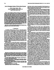
Fig. 1. System block diagram. The source transmits to the relay and destination in the first hop and the relay forwards to the destination in the second hop. Therefore, two time slots are required to complete the transmission of one OFDM symbol.
0
10
Un−coded BER
−1)
−
(32)
𝜎𝑧2 𝑁 𝜋𝛽𝑠𝑑 𝑇𝑠 𝜎2 1 1 ; 𝑐2 = 𝑧 ( + + ) ℰ𝑥 3 ℰ𝑥 𝑔𝑠𝑟 𝑔𝑟𝑑 (33) 𝑁 𝜋𝛽𝑠𝑟𝑑 𝑇𝑠 𝑐3 = 3 Comparing the results in (32) and (28), for the AF mode to achieve lower outage, we must have 𝑐1 =
−2
10
𝑃AF (𝑅) 3(2𝑅 − 1) 3Δ𝜔 3Δ𝜔 ≤ 1 ⇒ 𝛽𝑠𝑟𝑑 ≤ 2𝑅 ≈ = 𝑃Dir (𝑅) (2 − 1)2 𝑁 𝜋𝑇𝑠 𝜋8𝑅 𝜋∣𝐶∣3 (34)
−3
10
−4
10
−5
10
2𝑅
𝑐1 𝑒−(𝑐2 +𝑐3 )(2 −1) 𝑐1 − 𝑐2 − 𝑐3 × [1 − exp{−(𝑐1 − 𝑐2 − 𝑐3 )(22𝑅 − 1)}] 𝜋 2 𝑁 2 𝑇𝑠2 (22𝑅 − 1)2 𝛽𝑠𝑑 𝛽𝑠𝑟𝑑 ≗ 9 2𝑅
𝑃AF (𝑅) ≥ 1 − 𝑒−𝑐1 (2
where
Single−hop CPE comp. Single−hop perfect PHN AF CPE comp. AF Perfect PHN
10
(31)
where 𝑢 is a random variable representing the SINR of the direct link from source to destination. The probability in (31) can be computed after some straightforward algebra as
LNA
−1
0
Destination RF circuitry
0
5
10
15 20 SNR per bit (dB)
25
30
35
Fig. 2. Uncoded BER performance of AF relay assisted system. The constellation size is 16QAM or 𝑅 = 2 and 𝑛𝑅 = 1. The PLP is 0.32% and 𝑁 = 256.
probability that the transmission rate on the 𝑘th subcarrier is less than a threshold assuming 𝑛𝑅 = 1 is given by 1 𝑃AF (𝑅) = Pr( log2 (1 + 𝝆AF (𝑘)) < 𝑅) = Pr(𝝆AF (𝑘) < 22𝑅 − 1) 2 ≥ Pr(𝝆Dir (𝑘) + min[𝝆𝑠𝑟 (𝑘), 𝝆𝑟𝑑 (𝑘)] < 22𝑅 − 1) (29)
We first compute the PDF of the minimum of the SINR expressions from source to relay and from relay to destination. The CDF of the minimum of 𝝆𝑠𝑟 (𝑘) and 𝝆𝑟𝑑 (𝑘) is 𝐹𝝆Relay (𝑢) = 1 − [1 − 𝐹𝝆𝑠𝑟 (𝑢)][1 − 𝐹𝝆𝑟𝑑 (𝑢)] = 1 − exp{−
𝜎𝑧2 𝑢 1 1 ( + )} ℰ𝑥 𝑔𝑠𝑟 𝑔𝑟𝑑
𝜋 (𝛽𝑟,1 + 𝛽𝑠 )𝑁 𝑇𝑠 𝑢) 3𝜈 𝜋 (𝛽𝑟,2 + 𝛽𝑑 )𝑁 𝑇𝑠 𝑢)]−𝜈 × (1 + 3𝜈
× [(1 +
(30)
where Δ𝜔 = 1/𝑁 𝑇𝑠 is the subcarrier spacing and ∣𝐶∣ = 2𝑅 is the signal constellation size in direct mode. As it can be seen from (34), the upper bound on 𝛽𝑠𝑟𝑑 is linearly proportional to the subcarrier spacing and inversely proportional to the third power of the cardinality of the signal constellation in the direct mode. Moreover, this upper bound is independent of the largescale gains 𝑔𝑠𝑟 and 𝑔𝑟𝑑 at high SNR. For high transmission rates, the upper bound on 𝛽𝑠𝑟𝑑 in (34) becomes very small which imposes a stringent requirement on the allowable PHN level. For example, for a 20MHz bandwidth with 𝑁 = 64 subcarriers and 𝑅 is 4 bits per channel use, 𝛽𝑠𝑟𝑑 ≈ 70Hz. Assuming 𝛽𝑠 = 𝛽𝑑 = 𝛽𝑟,1 = 𝛽𝑟,2 , the PHN bandwidth normalized by the subcarrier spacing becomes only 0.005%. We refer to this ratio as PHN level percentage (PLP), which is defined by 𝑁 𝛽𝑖 𝑇𝑠 , for 𝑖 ∈ {𝑠, 𝑟, 𝑑} [32]. Remarks: 1. If the source and destination are free from PHN, the outage probability in the direct mode can be arbitrarily close to zero at high SNR (with diversity order equal to 1). However, the AF mode hits an error floor since it uses a noisy relay. At high enough SNR, the AF mode outage probability becomes worse than that of the direct mode. 2. If the relay node is free from PHN, both direct and AF modes hit an error floor because of the PHN in the source and destination. The bound on 𝛽𝑠𝑑 can be found from (34) by replacing 𝛽𝑠𝑟𝑑 with 𝛽𝑠𝑑 . In the absence of relay PHN, AF outperforms the direct mode at high SNR when the effect of PHN dominates.
This article has been accepted for inclusion in a future issue of this journal. Content is final as presented, with the exception of pagination. RABIEI et al.: ON THE PERFORMANCE OF OFDM-BASED AMPLIFY-AND-FORWARD RELAY NETWORKS IN THE PRESENCE OF PHASE NOISE
7
0
10
0
10
Single−hop CPE comp. Single−hop perfect PHN AF CPE comp. AF Perfect PHN
−1
10
−1
10 −2
Outage Probability
Un−coded BER
10
−3
10
−2
10
Simulation no PHN Analytical no PHN Simulation PLP = 0.32% Analytical PLP = 0.32% Simulation PLP = 0.06% Analytical PLP = 0.06%
−4
10
−3
10
−5
10
−4
10
0
5
10
15
−6
10
0
5
10
15 20 SNR per bit (dB)
25
30
20 25 SNR (dB)
30
35
40
35
Fig. 3. Uncoded BER performance of AF relay assisted system. The constellation size is 64QAM and 𝑛𝑅 = 2 which makes 𝑅 = 2. The PLP is 0.32% and 𝑁 = 256.
Fig. 4. Outage probability of the direct transmission system for different PHN levels. Solid lines are the upper bound results while dashed lines are simulations. 𝑁 = 64 and 𝑅 = 2.
0
10
VI. N UMERICAL R ESULTS −1
10
Outage Probability
We examine the BER and outage performance of an AF relay impaired by PHN. Since the relay has to down-convert the signal to baseband for amplification, the presence of PHN is inevitable in the receive chain. In addition, the upconversion to RF involves an oscillator impaired by PHN. Therefore 𝛽𝑟 = 𝛽𝑟,1 + 𝛽𝑟,2 is twice as large as 𝛽𝑠 or 𝛽𝑑 . In all of the simulations, 𝛽𝑠 = 𝛽𝑑 = 𝛽𝑟,1 = 𝛽𝑟,2 = 𝛽 and PLP = 𝑁 𝛽𝑇𝑠 . A DFT size of 𝑁 = 32, 64, 256 was used in different simulations and the OFDM signal bandwidth is 20MHz corresponding to 𝑇𝑠 = 50 nanoseconds. The channel between each pair of nodes is generated as a vector of complex Gaussian random variables of length 𝜈. For largescale channel fading, 𝛾 is set to 2. Based on the geometry of the relay network shown in Fig. 1 and by normalizing 𝑑𝑠𝑑 to one, 𝑔𝑠𝑟 and 𝑔𝑟𝑑 are computed. In our simulations, we chose 𝑑𝑠𝑟 = 0.5 and the angle between the links 𝑠 → 𝑟 and 𝑠 → 𝑑 is 𝜑 = 3𝜋/5 √ for which 𝑑𝑟𝑑 is computed to be 𝑑𝑟𝑑 = 𝑑𝑠𝑟 cos(𝜑) + 𝑑2𝑠𝑟 cos2 (𝜑) + 𝑑2𝑠𝑑 − 𝑑2𝑠𝑟 = 0.72 which results in a relay position roughly half way between the source and the destination. Therefore, the large-scale gains are 𝑔𝑠𝑟 = 4 and 𝑔𝑟𝑑 = 1.9. During the data OFDM symbol transmission, the number of pilots is 36 (for 𝑁 = 256), which are uniformly spaced across the OFDM symbol resulting in a pilot overhead of 14%. Fig. 2 depicts the AF mode uncoded BER performance as a function of SNR for 16QAM signal constellation or 𝑅 = 2 bits per channel use and 𝑛𝑅 = 1. As expected, the performance of the relay-assisted AF system is much better than the direct transmission case when there is no PHN. However, a significant performance loss is observed in the relay-assisted system in the presence of PHN. In fact, when CPE is compensated as described in Section IV-A, there is no performance benefit when using an AF relay. Fig. 3 shows the uncoded BER performance of the AF mode in comparison with the direct transmission mode when 𝑛𝑅 =
−2
10
−3
10
Simulation no PHN Analytical no PHN Simulation PLP = 0.32% Analytical PLP = 0.32% Simulation PLP = 0.06% Analytical PLP = 0.06
−4
10
−5
10
−6
10
0
5
10
15
20 SNR (dB)
25
30
35
40
Fig. 5. Outage probability of the dual-hop system for different PHN levels. Solid lines are the lower bound results while dashed lines are simulations. 𝑁 = 64, 𝑅 = 2 and 𝑛𝑅 = 1.
2. Note that in this case, the transmission rate is the same as in the previous scenario i.e. 𝑅 = 2. However, since three transmission time slots are required in the AF mode, the signal constellation size is increased to 64 QAM. Mathematically, if ∣𝐶∣ is the cardinality of the signal constellation, then for the AF mode we have 𝑅 = log2 ∣𝐶∣/(𝑛𝑅 + 1). The PLP and the DFT size are the same as in the previous simulation. The outage probability of the direct transmission case for different PLPs is presented in Fig. 4 together with the analytical result in (28). As it can be seen from the figure, at high SNRs the analytical results are upper bounds on the simulation. The DFT size is 𝑁 = 64 and the transmission rate is set to 𝑅 = 2 bits per channel use. The outage probability of the dual-hop system with 𝑛𝑅 = 1 and 𝑁 = 64 for different PLPs is shown in Fig. 5 where the transmission rate is set to 𝑅 = 2. Without PHN, second-order diversity is observed. However, with PHN, the performance degrades significantly. The lower bound on the outage per-
This article has been accepted for inclusion in a future issue of this journal. Content is final as presented, with the exception of pagination. 8
IEEE TRANSACTIONS ON COMMUNICATIONS, ACCEPTED FOR PUBLICATION
0
10
−1
−1
10 Channel Estimation MSE
Outage Probability
10
−2
10
Direct, PLP = 0.32% Direct, PLP = 0.06% Direct, PLP = 0 AF, PLP = 0.32% AF, PLP = 0.06% AF, PLP = 0
−3
10
−4
10
−2
10
−3
10
Proposed 0.08% PHN Proposed 0.32% PHN Conventional 0.08% PHN Conventional 0.32% PHN No PHN
−4
10 0
5
10
15
20 SNR (dB)
25
30
35
40 −5
10
Fig. 6. Outage probability comparison of the dual-hop and direct transmission systems for different PLPs. Dashed lines are AF mode while solid lines are direct mode. 𝑁 = 64, 𝑅 = 2 and 𝑛𝑅 = 1.
10
15 20 SNR (dB)
25
30
35
0
10
Dual−hop no PHN Dual−hop 0.32% PHN Single−hop no PHN Single−hop 0.32% PHN
−1
10
5 −2
10
4 Coded BER
PAF(R) / PDir(R)
6
5
Fig. 8. The MSE of the proposed channel estimator is compared with that of conventional estimator. 𝑁 = 64, 𝐿 = 2 and 𝑛𝑅 = 1.
N = 64,R = 2 N = 64,R = 3 N = 32,R = 2 N = 32,R = 3
7
0
3 Threshold 2
−3
10
−4
10
1 −5
0
10
0
1000
2000
3000 β
4000
5000 −6
10
Fig. 7. The outage probability ratio as a function of 𝛽𝑠𝑟𝑑 as defined in (6) for different DFT sizes and rates.
0
2
4
6
8 10 SNR per bit (dB)
12
14
16
18
Fig. 9. Coded BER performance. 𝑅 = 2 and PLP is set to 0.32%. The DFT size is 𝑁 = 256 and the OFDM sampling period is 1/𝑇𝑠 = 20MHz.
formance of the AF mode is loose since the upper bound 𝝆Relay ≤ min{𝝆𝑠𝑟 , 𝝆𝑟𝑑 } is lousy. To illustrate the effect of PHN level on the outage probability, Fig. 6 compares the outage probability of the direct transmission and dual-hop cases for three different PLPs. As it can be seen from the figure, when the PHN level increases, the AF mode suffers significant performance loss compared to the direct case. This confirms the earlier BER simulations and, therefore, can be used as a reliable criterion to study the effect of PHN. Note that transmission rate is fixed to 𝑅 = 2 for both AF and direct transmission modes. Fig. 7 depicts the ratio of the AF mode outage probability to the direct transmission outage probability versus 𝛽𝑠𝑟𝑑 . The range of 𝛽𝑠𝑟𝑑 for which this ratio is less than one (labeled as the threshold line on the figure) is the maximum allowable PHN level on the dual-hop system. As suggested by (34), this PHN level is determined by 𝑅 and 𝑁 which are variable parameters in Fig. 7. It is clear that the maximum allowable PHN for 𝑅 = 3 is much less than its value for 𝑅 = 2. The SNR is set to 35 dB for all curves.
The MSE of our proposed channel estimator is compared with that of the conventional estimator in Fig. 8. It is clear that there is a significant reduction in the MSE since PHN interference is mitigated in our scheme. To reduce the complexity of the estimator, 𝐿 was set to two. Finally, the coded BER performance is illustrated in Fig. 9 where the performance of the dual-hop case with CPE compensation is worse than the direct transmission case for a PLP of 0.32%. The DFT size is 𝑁 = 256, the transmission rate is 𝑅 = 2 and the rate 1/2 convolutional encoder [133, 171] with constraint length of 7 is used. This result motivates research into more advanced PHN compensation schemes for the AF relay mode which we are currently investigating. VII. C ONCLUSION Using outage analysis, we quantified the PHN level beyond which the performance of a dual-hop AF relay transmission with CPE only compensation becomes worse than direct
This article has been accepted for inclusion in a future issue of this journal. Content is final as presented, with the exception of pagination. RABIEI et al.: ON THE PERFORMANCE OF OFDM-BASED AMPLIFY-AND-FORWARD RELAY NETWORKS IN THE PRESENCE OF PHASE NOISE
transmission. In addition, we proposed low-complexity joint channel and PHN estimation and compensation schemes for preamble and comb-type OFDM-based AF relay transmission. We are currently investigating more advanced PHN compensation schemes to improve AF relay performance. R EFERENCES [1] A. Sendonaris, E. Erkip, and B. Aazhang, “User cooperation diversity– part I: system description," IEEE Trans. Commun., vol. 51, no. 11, pp. 1927-1938, Nov. 2003. [2] J. N. Laneman, D. N. C. Tse, and G. W. Wornell, “Cooperative diversity in wireless networks: efficient protocols and outage behavior," IEEE Trans. Inf. Theory, vol. 50, no. 12, pp. 3062-3080, Dec. 2004. [3] K. Y. Kim and R. Prasad, 4G Roadmap and Emerging Communication Technologies. Artech House, 2006. [4] R. U. Nabar, H. Bölcskei, and F. W. Kneubühler, “Fading relay channels: performance limits and space-time signal design," IEEE J. Sel. Areas Commun., vol. 22, no. 6, pp. 1099-1109, Aug. 2004. [5] “IEEE standard for local and metropolitan area networks part 16: air interface for broadband wireless access systems amendment 1: multiple relay specification," June 2009. [6] T. Pollet, M. Bladel, and M. Moeneclaey, “BER sensitivity of OFDM systems to carrier frequency offset and Wiener phase noise," IEEE Trans. Commun., vol. 43, pp. 191-193, Feb. 1995. [7] L. Tomba, “On the effect of Wiener phase noise in OFDM systems," IEEE Trans. Commun., vol. 46, pp. 580-583, May 1998. [8] T. Cover and A. A. E. Gamal, “Capacity theorems for the relay channel," IEEE Trans. Inf. Theory, vol. IT-25, pp. 572-584, Sep. 1979. [9] E. C. van der Meulen, “Transmission of information in a T-terminal discrete memeoryless channel," Berkeley, CA, Department of Statistics, University of California, 1968. [10] K. G. Seddik, A. K. Sadek, W. Su, and K. J. R. Liu, “Outage analysis and optimal power allocation for multinode relay networks," IEEE Signal Process. Lett., vol. 14, no. 6, pp. 377-380, June 2007. [11] Y. Zou, B. Zheng, and J. Zhu, “Outage analysis of opportunistic cooperation over Rayleigh fading channels," IEEE Trans. Wireless Commun., vol. 8, no. 6, pp. 3077-3085, June 2009. [12] S. Ikki and M. H. Ahmed, “Performance analysis of cooperative diversity wireless networks over Nakagami-m fading channel," IEEE Commun. Lett., vol. 11, no. 4, pp. 334-336, Apr. 2007. [13] G. K. Karagiannidis, T. A. Tsiftsis, and R. K. Mallik, “Bounds of multihop relayed communications in Nakagami-m fading," IEEE Trans. Commun., vol. 54, pp. 18-22, 2006. [14] Y. Song, S. D. Blostein, and J. Cheng, “Exact outage probability for equal gain combining with cochannel interference in Rayleigh fading," IEEE Trans. Wireless Commun., vol. 2, no. 5, pp. 865-870, Sep. 2003. [15] S. J. Kim, X. Wang, and M. Madihian, “Optimal resource allocation in multi-hop OFDMA wireless networks with cooperative relay," IEEE Trans. Wireless Commun., vol. 7, no. 5, pp. 1833-1838, May 2008. [16] Y. Ding and M. Uysal, “Amplify-and forward cooperative OFDM with multiple-relays: performance analysis and relay selection methods," IEEE Trans. Wireless Commun., vol. 8, no. 10, pp. 4963-4968, Oct. 2009. [17] X. Zhang, M. Tao, W. Jiao, and C. S. Ng, “End-to-end outage minimization in OFDM based linear relay networks," IEEE Trans. Commun., vol. 57, no. 10, pp. 3034-3044, Oct. 2009. [18] W. P. Siriwongpairat, A. K. Sadek, and K. J. R. Liu, “Cooperative communications protocol for multiuser OFDM networks," IEEE Trans. Wireless Commun., vol. 7, no. 7, pp. 2430-2435, July 2009. [19] F. Gao, R. Zhang, and Y. C. Liang, “Channel estimation for OFDM modulated two-way relay networks," IEEE Trans. Signal Process., vol. 57, no. 11, pp. 4443-4455, Nov. 2009. [20] B. Jiang, H. Wang, X. Gao, S. Jin, and K. K. Wong, “Preamble-based channel estimation for amplify-and-forward OFDM relay networks," IEEE Globecom, Dec. 2009. [21] C. S. Patel and G. L. Stüber, “Channel estimation for amplify and forward relay based cooperation diversity systems," IEEE Trans. Wireless Commun., vol. 6, no. 6, pp. 2348-2356, June 2007. [22] B. Gedik and M. Uysal, “Impact of imperfect channel estimation on the performance of amplify-and-forward relaying," IEEE Trans. Wireless Commun., vol. 8, no. 3, pp. 1468-1479, Mar. 2009. [23] Z. Zhang, W. Zhang, and C. Tellambura, “Cooperative OFDM channel estimation in the presence of frequency offsets," IEEE Trans. Veh. Technol., vol. 58, no. 7, pp. 3447-3459, Sep. 2009.
9
[24] Y. Li, “Pilot-symbol-aided channel estimation for OFDM in wireless systems," IEEE Trans. Veh. Technol., vol. 49, no. 4, pp. 1207-1215, July 2000. [25] P. A. Anghel and M. Kaveh, “Exact symbol error probability of a cooperative network in a Rayleigh-fading environment," IEEE Trans. Wireless Commun., vol. 3, pp. 1416-1421, Sep. 2004. [26] A. Demir, A. Mehrotra, and J. Roychowdhury, “Phase noise in oscillators: a unifying theory and numerical methods for characterization," IEEE Trans. Circuits Systems I, vol. 47, no. 5, pp. 655-674, May 2000. [27] P. Liu, Y. Bar-Ness, and J. Zhu, “Effects of phase noise at both transmitter and receiver on the performance of OFDM systems," in Proc. 40th Annual Conf. Inf. Sciences Syst., pp. 312-316, 2006. [28] P. Rabiei, W. Namgoong, and N. Al-Dhahir, “Frequency domain joint channel and phase noise estimation in OFDM WLAN systems," in Proc. 42nd Asilomar Conf. Signals, Syst. Comput., pp. 928-932, 2008. [29] G. J. Foschini and G. Vannucci, “Characterizing filtered light waves corrupted by phase noise," IEEE Trans. Inf. Theory, vol. 34, no. 6, pp. 1437-1448, Nov. 1988. [30] S. Wu and Y. Bar-Ness, “OFDM systems in the presence of phase noise: consequences and solutions," IEEE Trans. Commun., vol. 52, no. 11, pp. 1988-1996, Nov. 2004. [31] E. L. Lehmann, “Some concepts of dependence," Annals Mathematical Statistics, vol. 37, no. 5, pp. 1137-1153, 1966. [32] B. Razavi, RF Microelectronics. Prentice-Hall, 1998. Payam Rabiei (S’05) received the M.S. degree in electrical engineering from The Uiversity of Texas at Dallas 2007. Since January 2008, he has been working toward his Ph.D. degree in the department of electrical engineering and computer science, the university of Texas at Dallas. His research interests include signal processing for communications. He was a member of technical staff at ASSIA inc. during summer of 2010 where he was working on noise cancellation for DSL systems. Won Namgoong received the B.S. degree in Electrical Engineering and Computer Science from the University of California at Berkeley in 1993, and the M.S. and Ph.D degrees in electrical engineering from Stanford University in 1995 and 1999, respectively. He is currently an Associate Professor of the Electrical Engineering Department at the University of Texas at Dallas. Previously, he was with the University of Southern California and Atheros Communications. His current research activities include signal processing systems and RF/analog circuits. He served on the editorial boards of the IEEE T RANSACTIONS ON C IRCUITS AND S YSTEMS I - Regular Papers and the Journal of Signal Processing Systems. He received the National Science Foundation (NSF) Faculty CAREER Award in 2002. Naofal Al-Dhahir : earned his PhD in Electrical Engineering from Stanford University in 1994. From 1994 to 2003, he was a principal member of the technical staff at the R&D Labs of GE and AT&T. In 2003, he joined UT-Dallas where he is currently the Jonsson distinguished professor of engineering. He has authored over 220 journal and conference papers and holds 29 issued US patents. He is an Editor for IEEE T RANSACTIONS ON C OMMUNICATIONS . He is co-recipient of the IEEE VTC Fall 2005 best paper award, the 2005 IEEE signal processing society young author best paper award, the 2006 IEEE Donald G. Fink best journal paper award and is an IEEE fellow.