On the Realisation of Delay-Insensitive Asynchronous Circuits with CMOS Ternary Logic R.Mariani, R.Roncella, RSaletti, P.Terreni Dipartimento di Ingegneria dell’hformazione: Elettronica, Informatica, Telecomunicazioni, University of Pisa, Via Diotisalvi 2,I-56126 Pisa, Italy E-mail:
[email protected] the difficulty of building non-trivial ternary circuits discouraged the investigation on asynchronous multivalued logic [4], but recently, improved and reliable CMOS multivalued logic has been reported [5] and its use in asynchronous circuits has been proposed [6]. This paper shows how Delay-Insensitive (DI) asynchronous circuits can be obtained with a CMOS multivalued (ternary) logic. The basic idea is a wire and power efficient handshake protocol that utilises transitions to the intermediate (third) logic level to separate different events. It is then shown that complex networks can be designed using basic DI elements. Finally, the CMOS ternary logic asynchronous approach is related to other solutions, by comparing the structure of common elements such as the C-Muller and the adder.
Abstract The realisation of Delay-Insensitive (DI) asynchronous circuits with a CMOS ternary logic is described in this paper. The main advantage of temary logic is the easy realisation of a handshake protocol that significantly reduces the communication requirement, one of the major drawback of asynchronous logic. It is shown how general purpose delay-insensitive circuits are designed with standard ternary logic elements and an original completion detection circuit called watchful. Some elemental circuits (shift-register and adder} are designed and simulated and their performance is compared with other asynchronous solutions, showing that a better performance in term of power consumption has been achieved.
2. DI ternary circuit basics Asynchronous circuits are generally classified according to the timing model assumed to consider the internal (gate) and external (communication wires) delays. In bounded-delay models it is assumed that the delay in circuit elements and wires is known, or at least bounded; signal encoding and race-free synthesis allow the elimination of hazards [71. In micropipelines [8], speed-independent and quasi-delay-insensitive circuits [9] gate delays are considered unbounded, but some constraints on wire delays are necessary. The most general model of asynchronous circuit is the DelayInsensitive, in which the delays in both gates and wires are unbounded. A handshake protocol is therefore required to guarantee that a signal has eventually reached its proper value. DI handshake protocols can be classified by the set of signalling transitions occurring between the sender (SE) and the receiver (RE) elements. In a two-phase handshaking a request transition is sent from SE to RE, and a response transition is sent back 5y the RE completion detection logic. In four-phase handshaking a second requesthesponse transition set is needed, so that
1. Introduction Asynchronous circuits are considered inherently less power consuming than other circuits, since only those nodes belonging to areas involved in the computation are interested in transitions. Moreover, they allow the overcoming of all the problems due to clock generation and distribution in synchronous systems. The low-power feature of asynchronous circuits has been demonstrated, particularly in strongly data-dependent applications [1],[2]. On the other hand, the main drawbacks of asynchronous circuits should bc considered: first, the presence of a communication protocol determines a significant increase in circuit complexity becoming dramatic at high numbers of input and output; second, the design is less straightforward and more critical since races and hazards should be avoided [ 3 ] . A possible way to reduce the number of signals involved in the communication is to increase their information content as in multivalued logic. In the past,
54 0-8186-7922-0197$10.00 0 1997 IEEE
the communication wires are returned to their initial values. Another classification is based on whether the handshake logic is integrated with the data logic: singlerail logic uses one wire per bit and one data-valid wire per data word, whereas double-rail logic combines in two wires the data bit and the data-valid wire. Depending on the protocol, an extra number of connecting wires is needed; at least two wires are required from SE to RE to transfer one data bit with transition single-rail signalling or with double-rail encoding [I]. Thus, a handshake channel of N bit between two elements requires 2N + 1 wires. The wiring of the double-rail approach can be reduced by coding the data (in the four-state scheme described in [IO] a Gray code is used), but more involved encoding and decoding circuits are needed for sender and receiver. Finally, bundled data single-rail signalling uses only one wire per bit and one or two [ll] control wires per data word, but it cannot be considered DI, because it has to be assumed that the control wire delay is larger than that in each of the data wires. Recently, a single-rail handshaking signalling applied to micropipeline has been presented [12]; this approach requires only one wire per handshake channel and two transitions to realise a fourphase handshake protocol, using tristate CMOS gates to drive the control wire [ 131. The basic idea of the ternary logic approach is the use of a two-phase ternary handshake protocol which allows the reduction of the communication wires without violating the DI assumption. Three logic levels are used: a logic high VH,a logic low VLand an jntermediate value VI that does not represent a true logical value. In our signalling approach (Fig. 1) a V, level on the data wire implics that thc SE is not rcady to scnd a new data (say SE is in idle, waiting for new input data, or is busy because it is computing new data). As soon as SE has a data available, the wire changes to the data logic level (e.g. V,); the RE reads this transition as a request and stores the data value. As soon as the data is stored, RE acknowledges SE pulling up the full wire; finally, as a consequence of this acknowledgement, SE resets itself to the VI level. It will start a new handshake as soon as a new data is available.
It is immediately apparent that the single data wire is “double-railed” by the ternary logic, because the request signalling is merged with the information. Therefore, we can conclude that a handshake channel of N bit requires only N + 1 wires. This results in an undoubted saving in the complexity of the communication channel that can significantly improve a routing limited performance. A second consequence of the identity between information and signalling is that no assumption is made on delays, making these circuits in full compliance with the DI model. It is not difficult to show that this property is maintained in multiple input - multiple output elements as well, if the acknowledgement signals are properly managed. Therefore, the so-called Foam Rubber Wrapper constraint [I41 stating that “for any DI circuit we must be able to attach arbitrary delays on the input and output lines, and the new interface created must have the exact same behaviour as the original module with no hazards”, is satisfied. It should also be noted that the “return to zero” phase, required in dual-rail encoding with level sensitive signalling to reset the initial levels [14], is automatically achieved in our approach, when the logic level returns to the intermediate value. Moreover, the V, transition (often called the spacer between two evaluations) is much more power efficient and can be directly caused by the full transition on very simple dynamic ternary gates, as it will be shown later. The simplest case of a single-input single-output DI element, the basic element with which more complex DI elements are built, is the “watchful”. Fig. 2 shows a watchful W and its timing diagram. Let us suppose the input at VI and W in the idle state with the full signal low and the output set to VI. As soon as a valid data ( i n t V ~ ) appears at the input, it is stored by W ( o u t t i n ) and the acknowledgement is sent C f u l l t V,). Therefore, the sender may resets itself to VI and compute a new data; in the meantime, W holds its output until a clear signal resets it (the clear is nothing but the full signal of a cascaded watchful). When W has been reset, the cycle repeats. The transition from VI to VH (or VL)acts as a sender request and therefore a VI phase always exists between two data. The minimum duration of this phase occurs if clear resets W when a new data is already available, as the timing diagram of Fig. 2 shows. The watchful consists of a memory unit (MU) that stores the valid data (as a pipeline register does in a synchronous approach), and a full engine (FE) that acts as completion detection circuitry, as it will be detailed in Fig. 4.
data sent data read
VL or VH RE
acknowl.
RE
[:
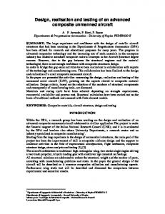
vu4 Fig. 1:Two-phase ternary handshake protocol.
55
I
full
clear
Fig. 2: Watchful W and its timing diagram: the clear is the full signal coming from a cascaded watchful. 1 pm n-well CMOS technology process, with threshold voltages of 0.76 V (NMOS) and -1.04 V (PMOS), we chose VH= 4 V, VI = 3 V and VL= 2 V. This choice is not fully satisfying, as far as the noise margins and the transition speed are concerned. Furthermore, at least 4 power supplies are needed: in fact, it is not possible to use the same three voltages for data, substrate and control signal level, in order to obtain sufficient noise margins and to correctly drive the intermediate voltage precharge transistor. If it was possible to slightly modify the process threshold voltages to suit the ternary approach, we would obtain VH= 3.3 V, VI = 1.65 V, VL= 0 V and better noise performance. Only three power supplies would thus be needed.
3. Ternary logic The asynchronous approach described in this paper is a sort of multivalued logic (MVL), even if the intermediate level has not a real logical meaning. In general, multivalued logic requires complex, area expensive circuitry or very customised process modification are needed; very often MVL also means a high power dissipation [ 5 ] . The DI ternary approach uses the CMOS dynamic ternary logic proposed in [SI because of its simple implementation, since this logic has no dc power dissipation and maintains the voltage levels. The basic element is the Simple Ternary Inverter (STI, Fig. 3), designed in a dynamic form, i.e. a control signal is needed to pull the gate output to the intermediate level. The control signal is replaced by thefull signal generated by the watchful FE, in the DI ternary approach. Three voltage levels are involved: VH,VI and VL.
4. General-purpose DI circuits The watchful has to be associated with a Ternary Logic Element (TLE) to perform asynchronous functions. Whereas the watchful realises the completion detection and memorisation circuitry, the TLE computes the outputs for any required logic function (Fig. 4).
VH
I
in
b
--+ out
b
MU
0
--*
h
c-
FE full4
2
4
=
TLE
I
clear
Fig. 3: The Simple Ternary Inverter (STI) as an example of CMOS ternary logic.
Fig. 4: A general-purpose DI ternary block, composed by a Watchful and a Ternary Logic Element
These levels strongly depend on the MOS threshold voltage of the available technology; with a VI input level have to be Off, and the vH both the and the and VLlevels should be chosen to have symmetrical VHVI and VI- VL swings. Being available a commercial
Using this structure, multi-input and multi-output DI ternary elements can easily be created: Fig. 5a, for example, shows a one-input two-output element, the clear signal of which is obtained with an additional Clear Engine (CE) realised as a join operator (i.e., only when
56
both A and B have been read by the cascaded watchfuls, new data can be processed by W). Fig. 5b shows a twoinput one-output element: the full signals can separately acknowledge two different processing branches.
n .i
.
because a direct transition V, H VH is not possible, spurious transition hazards are removed. However, a so-called “handshake” hazard, i.e. a valid TLE output even if one of the input is still VI, can still occur. Fig. 6 shows that a handshake hazard cannot occur if the output of the ternary gate is forced at VI for any input at VI. In fact, let us suppose the two watchful outputs oA and OB at VH(so out is VL),and suppose that both oA and OB change to VL after the clear rising edge. A handshake hazard cannot occur even if a delay A exists between the two signals C and D in the TLE, being out forced at VIuntil at least one of the inputs is at Vi. It can easily be demonstrated that STI and STXOR ternary gates have the intrinsic behaviour of maintaining a Vi output until any one of their inputs is Vi. In the other cases there is always a way to build an hazard-free TLE, regardless of the logic function performed: for example, if the output has to remain at Vi until every input is valid, we could force the output with thefull signals of the input watchfuls. The output is left only when everyfull is high, i.e. when every input has its proper data value.
-
r
................................................ ..................................
4-zjzjflJ W2
TLE2 dear
:
5. The low-power features of the DI ternary
...................................
approach The DI ternary approach can reduce power consumption as compared to other asynchronous solutions. The dominant source of power consumption ([15], [16]) in digital CMOS circuits is switching dissipation, which depends on the square of AV, the voltage swing. Dynamic power consumption in asynchronous circuits is due to the data movement and control signalling; the latest is the counterpart of the clock distribution consumption in synchronous circuits. In our approach there are two possible voltage transitions, i.e. VH ++ Vi and V, ++ V,: SO A V = VH - V i = V i VL= (VH - VL)/2, if Vi = (VH + VJ2 (AV = 1 V in our case). This is the way by which a low-power behaviour, comparable to that of supply-voltage reduced systems (i.e. down to VDD= 1 V), without reducing as much the voltage levels, but only the voltage swings, is achieved. The obvious drawback is that noise margins are reduced
Fig. 5: General-purpose DI Ternary circuits: a) oneinput two-outputs , b) two-input one-output. The TLE is constituted of Standard Ternary Gates, the precharge of which to the intermediate level is controlled by the watchful (the precharge signal is automatically generated by the FE). The design of the ‘ L E can be made with standard design techniques, for example using ternary A01 complex gates. An interesting feature of TLE is that spurious transition hazards are eliminated due to the property of simple ternary dynamic gates of producing a valid output (i.e., not VI) only if the input values are sufficient to decide the output value: for example, a Simple Ternary NAND gate (STNAND) with one of the input at Vi will produce a valid output only if the other input is VL.Thus,
.................................. ,
c
full
w2
J J
i TLE clear
Out
1
-
L
Fig. 6: How handshake hazards can be avoided.
57
as well. The DI ternary approach involves a simpler circuitry to generate the completion signal (i.e. the full) than other asynchronous solutions; besides, the lower number of data wires reduces the gate area and the “drive” power needed to transmit the same amount of information. Like every dual-railed coding, more transitions than those strictly necessary are needed to move between the spacer and the valid output; however, in the DI ternary approach these transitions are very power efficient, because involve only one data wire for each data bit and the voltage swing for each transition is AV only. And this power saving grows with the number of data bits; for example, in the dual-rail four-phase handshake of [11, where each message is communicated by pulling up one wire per bit pair, a complete transition 0 4 2 in a two-bit data bus requires a 0000-+0101-+0000-+1001-+0000 transition, i.e. 8 times a VDDvoltage swing, whereas we have a VIVI-+VLVL-+VIVI+ VHVL+VIVI transition in our approach, with 8 times an only (VH- V J 2 swing. Another low-power feature of our approach is that the removal of combinational hazards obtained by a proper design of the TLE can save a contribute to between 9% and 38% of the power consumption of CMOS circuits [ 171. Furthermore, because of the simplicity of the hazard-free TLE design (as mentioned before), this power reduction is not affected by an increased complexity of the architecture.
6. The watchful circuit design Many circuit realisation of the watchful are possible. Fig. 7 shows the transistor schematic of a DI ternary element composed by a watchful (with the FE and the MU) and a modified TLE register; this circuit has been used to build an asynchronous shift-register [6].The MU and the TLE have been realised with a dynamic TrueSingle-Phase-Clock (TSPC)-like structure [ 181, using NTI and PTI ternary gates [5]; it can be noted that TLE is partially merged with the MU in a fast dynamic structure to achieve the highest performance. Looking into the watchful schematic, we note that F E generates the full (and its complement fulln); as soon as the output is different from VI the hold signal goes down and full goes high. A clear rising transition resets the full to V,. If full is low (fulln is high), the output of the TLE is kept at VIby the weak transistors Q1 and Q2; in that way a quasi-dynamic structure has been built. It is worth noting that to hold the intermediate level raises the power dissipation but avoids further degradation of the noise margin. Using a different structure, a complete dynamic watchful could be built; in that case a clear rising transition generates an internal reset pulse, and the output floats until the input is VI.If a continuous dynamic operation is not guaranteed, a refresh mechanism must be provided; otherwise, a fully static circuit can be designed with the evident drawback of a larger area occupation. Tab. 1 shows a comparison between the watchful and other similar asynchronous completion detection element,
out
clear
outrn
I
f
TLE
)
\,
Sutherland89 [8] watchful DeGloria94 [ 191 wuu93 [20]
22
,
\r
1470 3010 1317 2590
1.5 2.3 3.8 3.1
,
46 55 117
110
Tab. 1:A comparison between some elementary asynchronous circuits. such the first C-Muller Element introduced by Sutherland [8], a standard-cell based DI C-Muller [I91 and an areaefficient modular self-timed element [ 201. In order to make an unbiased comparison, all the circuits have been redesigned with the same procedure and the same 1pm CMOS technology. The transistor dimensions are not optimised and no external load is considered; an automatic synthesiser has been used to obtain the layout. Simulations have been performed on the layout extracted schematics with a continuous input pattern at a data throughput of 40 MHz. It has to be noted that the Sutherland C-Muller is defined for micropipelines, that do not satisfy the DI requirements: therefore that solution can be seen as a lower bound for DI circuit performance. Furthermore, it should also be taken into account that the watchful performs a more complex handshake function than CMuller does, since it contains an input register, it generates the acknowledgement and it can be reset. Nevertheless, the watchful shows good power and speed figures with respect to the other circuits. As expected, the reduced logic swing leads to a significant decrease of power dissipation as compared to the other DI solutions. The area occupation is not favourable to the watchful, but we must also consider that it has not been taken into account the most significant advantage of DI ternary logic; the reduced number of communication wires. This factor has not weighted at all in the comparison, and it has an importance that strongly increases with the number of input. Finally, compared to coded-data double-rail approach where decoding circuits are needed for sender and receiver (e.g. [10],[21]), it can be noted as the area overhead due to the watchful and to the decoding circuitry are comparable. However, it is worth noting that the watchful implementation does no1 depend on the particular application, as it happens for the decoding circuits. It has been shown elsewhere that hvgh performances can be obtained with an optimised watchful design: a DI asynchronous ternary shift-register has been designed, with an area occupation of 70x70 pm2 for each stage and a maximum average data throughput speed of about 350 MHz [6].
7. DI ternary addition Addition is generally needed in all digital processors, and its low-power high-performance realisation is a key factor to achieve the best design results. Many architectures for addition exist [22], both synchronous and asynchronous, and the former seems to have the lowest power and best energy-product per addition figure [23]. Furthermore, it has been shown that in dynamic adders, where the transition hazards are eliminated by means of a precharge phase, there is a substantial increase in the number of transitions per node [24] and therefore power dissipation tends to increase. Using the DI Asynchronous Ternary Logic, many of the known adder structures can be realised; in this paper we consider the Bit-Serial Adder (BSA) and the parallel Ripple-Carry Adder (RCA) [22]. Both can be built with watchfuls and ternary logic complex gates according to the procedure shown in the previous section. Tab. 2 summarises the design and simulation results in term of transistor number, average addition time and average energy per operation for 32 bit operands (100 random patterns have been used for power consumption evaluation). Avg. Energy time (ns) 147.2 33.5
31.6
Tab. 2: Adder realisations with the DI ternary logic. The BSA realisation is shown in Fig. 8; it consists of an asynchronous full-adder (a three-input two-output DI block) and an asynchronous register which stores the carry. The full-adder is made with ternary complex gates, as shown in Fig. 9, using the same architecture of the binary realisation [22], in which the carry output is used also to obtain the sum. The full-adder of Fig. 9 can be employed to realise an asynchronous parallel RCA. Its performance is determined by the carry propagation delay. Fig. 10 shows the results of the ternary full-adder exhaustive simulation, where the inputs A , B , Ci,and the outputs S and CO,,are reported. The results are summarised in Tab. 2. As
59
energyloperation of 75.05pJ for a RCA adder (with a cycle time of 30 ns), almost a factor 2 larger than the ternary one, at comparable speed. Better power figure could be obtained with a process customised for ternary operations (as considered in section 3). Furthermore, we should mention again that the ternary solution completely fulfils the DI model, and therefore it is less convenient in term of transistor number (about 25% more) with respect to the other solutions that are not DI. Finally, the speed operation achieved is comparable, even if the ternary logic design has transistor dimensions not optimised.
expected, the BSA exhibits a low speed performance (computed as the average addition cycle delay times 32) as compared to the RCA, whereas it is better as far as area occupation and power dissipation are concerned. ............................................... Full Adder
4-
-+
FA
8. Conclusions The realisation of Delay Insensitive Asynchronous Circuits using a CMOS Ternary Logic has been presented and discussed in this paper. It has been shown that the most interesting feature of the DI ternary logic is the reduction of the communication requirements due to the use of a ternary handshake protocol. A CMOS ternary completion circuit called watchful has been designed and simulated, and some examples of general-purpose DI ternary circuits has been described. The DI ternary logic approach has been compared to other existing asynchronous solutions. The C-Muller element and some realisation of the addition have been investigated. It has been shown that, being less favourable in term of area
...............................................
Fig. 8: A bit-serial adder realised with the DI ternary logic. If we compare the ternary RCA with other adder realisations [23], [24] we observe that ternary solution is the best as far as power consumption is concerned. In fact, the best reported results have an energyloperation of 65.5 pJ for an adder based on the Manchester ATLAS adder (with a cycle time of 22ns) and an
Fig. 9: A DI ternary complex-gate full-adder realisation.
60
proposed as an effective way of designing low-power asynchronous systems.
occupation, the DI ternary logic has however significantly reduced the power consumption, maintaining comparable speed performance. Therefore, the DI ternary logic is
I
I
I
I
I
75.0n
I
I
I
100.0n
125.0n
150.0n
175.0n
20O.On
225.0n
250.0n
275.0n
time ( I l n )
300 300. On
Fig. 10: A simulation of the DI asynchronous full adder.
[6] R. Mariani, R. Roncella, R. Saletti, P. Terreni, “Delayinsensitive asynchronous circuits with CMOS ternary logic for low power applications”, Proc. of the 6Ih Int. Workshop on Power, Timing, Modeling, Optimization and Simulation PATMOS’96, Pitagora Editrice Bologna, pp.135-144, September 1996.
References [l] K. van Berkel et al., “A Fully Asynchronous Low-Power Error Corrector for the DCC Player”, IEEE JSolid-State Circ., vol. 29, no. 12, pp. 1429-1439, Dec. 1994.
[7] C.Piguet, “Logic Synthesis of Race-Free Asynchronous CMOS Circuits”, IEEE JSolid-State Circ., vol. 26, no. 3, pp. 371-380, March 1991.
[2] L.S. Nielsen et al.,”Low-Power Operation Using SelfTimed Circuits and Adaptive Scaling of the Supply Voltage”, IEEE Trans. VLSI Syst., vol. 2, no.4, pp. 391397, Dec. 1994.
[8] I. Sutherland, “Micropipelines”, Commun. ACM, ~01.32, no.6, pp. 720-738, June 1989.
[3] M.Afghahi, C.Svensson, “Performance of Synchronous and Asynchronous Schemes for VLSI Systems”, IEEE Trans. Comput., vo1.41, no.”, pp. 858-872, Jul. 1992.
[9] A.J. Martin “Programming in VLSI: From communicating processes to delay-insensitive circuits ”, UT Year of Programming Institute on Concurrent Programming, C.A.R. Hoare, Ed. Reading, MA: Addison-Wesley, 1989, pp. 1-64.
[4] A.S.Wojcik, K.Fang, “On the design of Three-Valued Asynchronous Modules”, IEEE Trans. IComput., vol. C29, no.10, pp. 889-898, Oct. 1980. [5]
[lo] A.J. McAuley “Four State Asynchronous Architectures”, IEEE Trans. Comput., vol. 41, no.2, pp, 129-142, Feb. 1992.
C. Wu, H. Huang, “Design and Application of Pipelined
Dynamic CMOS Ternary Logic and Simple Temary Differential Logic”, IEEE JSolid-State Circ., vol. 28, no. 8 , pp. 895-906, Aug. 1993.
[ l l ] Furber S.B. et al., “A Micropipelined ARM.”, Proc. of
VLSI ‘93,Grenoble, France, Sept. 1993.
61
[121 K.V.Berke1,
A. Bink, “Single-Track Handshaking Signaling with Application to Micropipelines and Handshake Circuits”, Proceedings of ASYNC’96, 1996.
[13] 1.E.Sutherland et al., “The Trimosbus”, Proc. ofthe First Caltech Confgrence on VLSI, pp. 395-427,1979. [ 141
S.Hauck, “Asynchronous Design Methodologies: An Overview”, Proc. IEEE, vo1.83, no.l, pp. 69-93, Jan.1995.
[15] A.P. Chandrakasan et al., “Low-Power CMOS Digital Design”, IEEE JSolid-State Circ., vol. 27, no. 4, pp. 473483, April 1992. [16] D. Liu, C. Svensson, “Power Consumption in CMOS VLSI Chips”, IEEE JSolid-State Circ., vol. 29, no. 6, pp. 663-670, June 1994. [17] Benini L., Favalli M., Riccb B., “Analysis of Hazard Contribution to Power Dissipation in CMOS ICs.”, 1994 Int. Workshop on Low Power Design., NAPA Valley, April 1994. [18] J.Yuan, C. Svensson, “High-speed CMOS Circuit Technique”, IEEE JSolid-State Circ., vol. 24, no. 1, pp. 62-69, Feb. 1989. [19] A. De Gloria, P. Faraboschi, M. Olivieri, “Design and Characterization of a Standard Cell Set for Delay Insensitive VLSI Design”, IEEE Trans. Circ. Syst. II, vol. 41, no. 6, pp. 410-415, June 1994. [20] Tzyh-Yung Wuu, S.B.K. Vrudhula, “A Design of a Fast and Area Efficient Multi-Input Muller C-Element”, IEEE Trans. VLSI Syst., vol. 1, no.2, pp. 215-219, June 1993. [21] A.J. McAuley, “Dynamic Asynchronous Logic for HighSpeed CMOS Systems”, IEEE J. Solid-state Circuits, vol. 27, no. 3, pp.382-388, Mar. 1992. [22] N. Weste, K. Eshragian, “Principle of CMOS VLSI Design - A Systems Perspective”, Addison Wesley, 1993. [23] D.J. Kinniment, “An Evaluation of Asynchronous Addition”, IEEE Trans. VLSI Syst., vol. 4, no.1, pp. 137140, March 1996. [24] D.J. Kinniment, J.D. Garside, B.Gao, “A Comparison of Power Consumption in Some CMOS Adder Circuits”, Proc. of the 5Ih Int. Workshop on Power, Timing, Modeling, Optimization and Simulation PATMOS’95, Oldenburg, Germany, Oct. 1995.
62