Nov 27, 2006 - Matthew J. Lockyear, Alastair P. Hibbins, Kevin R. White, and J. Roy Sambles ..... [3] H. A. Rowland, Physical Papers (John Hopkins, Baltimore,.
PHYSICAL REVIEW E 74, 056611 共2006兲
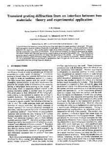
One-way diffraction grating Matthew J. Lockyear, Alastair P. Hibbins, Kevin R. White, and J. Roy Sambles Electromagnetic Materials Group, School of Physics, University of Exeter, Exeter EX4 4QL, United Kingdom 共Received 11 May 2006; published 27 November 2006兲 Diffraction gratings are elementary tools for much of optics and spectroscopy. Here, at microwave frequencies, we provide a new perspective on these fundamental structures. A transmission diffraction grating is presented that has diffracted beams emanating from one surface only. It can thus function either as a transmission grating with no reflected orders 共other than zero兲 or, in the reverse configuration, as a partially transmitting structure with diffracted orders in reflection only. DOI: 10.1103/PhysRevE.74.056611
PACS number共s兲: 42.25.Bs
The study of the diffraction of light by obstacles goes back to Newton and beyond, but the study of diffraction gratings dates only to the late 18th century 关1兴, with their use in spectroscopy in the early part of the nineteenth century 关2兴. Mass production of reflection gratings followed due to the development of ruling engines 关3兴, and since then, this fundamental device has been employed extensively across the whole electromagnetic spectrum. In recent years considerable attention has been focused upon the study of metal transmission gratings structured on the subwavelength scale, this renewed interest largely being due to the observation of enhanced transmission phenomena associated with the excitation of waveguide and surface plasmon resonances 共关4–6兴 and references therein兲. Here we make an important advancement in this field, by studying the microwave response of a grating that supports diffracted beams in one direction only, either transmission or reflection. We therefore label this device a “one-way diffraction gating.” The structure used to achieve this unusual behavior is shown in the inset of Fig. 1. A repeat unit of the structure is comprised of four air-filled 0.25-mm-wide slits which cascade to a single slit in a metal plate, which may be considered as near perfectly conducting and opaque at these wavelengths. In this manner the groove periodicity on one side of
the sample 共⌳g = 18.0 mm兲 is made four times that on the other 共g = 4.5 mm兲. In accordance with classical waveguide theory 关7兴, a parallel sided subwavelength slit in a metal plate may support a propagating mode with magnetic field parallel to the cavity walls for any width. When the length of this slit is finite, a set of Fabry-Perot-like standing wave resonances may be supported 关8兴 along its length, according to the condition N 艌
2nL , N
where N is the mode number, n is the refractive index of the material filling the slit, and L is the slit length, with the equality becoming exact in the limit of infinitesimal slit width for a perfect conductor 关9,10兴. The structure under consideration here is comprised of an array of many air-filled slits. Note that our device cannot be considered as a stack of three separated arrays 共periodicities 4.5 mm, 9 mm, and 18 mm兲 since the dielectric region between each layer is not unbounded. For narrow slit widths 共w兲 the establishment of modes within such structures is not significantly perturbed by placing bends in the slits, since for w ⬍ 0, where 0 is the wave-
FIG. 1. The transmission spectra 共circles兲 obtained when illuminating the nondiffracting surface with plane-wave radiation at = 0°, = 0° and having the electric field vector perpendicular to the grating cuts. The theoretical electromagnetic response of the sample is also shown 共solid line兲, obtained from an FEM model 关12兴. Inset: A schematic representation of a section of the transmission grating under study, together with the experimental arrangement.
1539-3755/2006/74共5兲/056611共4兲
056611-1
©2006 The American Physical Society
PHYSICAL REVIEW E 74, 056611 共2006兲
LOCKYEAR et al.
FIG. 2. The transmission spectra obtained from the sample over a reduced frequency range for which the short pitch surface 共g兲 is zero-ordered, and the long pitch surface 共⌳g兲 is diffracting. The solid line represents the spectra obtained when the zero-ordered periodicity is illuminated at = 0°, and the squares represent the transmission obtained in the alternative sample orientation for which = 0°. Inset: The two sample orientations are illustrated by a schematic of the structure together with the incident beam 共I兲, the zeroth order 共T0 and T⬘0兲 transmission, the specular reflection 共R0兲, and in addition, the transmitted 共T+, T−兲 and reflected 共R+ , R−兲 diffracted orders.
length of the incident radiation, the path change associated with the corners is small compared to the resonant wavelength 关11兴. It is then possible to merge two or more subwavelength slits via a three-port “T junction.” When fields entering through the two equivalent input ports are driven in phase, power combination and propagation through the exit port occurs. Conversely, power division may also occur when fields enter the junction via the unmatched single port and exit via the two matched ports, leading to a transmitting structure in which there are more exit than entrance channels or vice versa. In the sample studied here, the slits are formed in an aluminum alloy block of dimensions 300⫻ 300⫻ 20.5 mm, with the Fabry-Perot-like modes supported between the illuminated and exit faces of the sample 共total path length L = 27.25 mm兲. In addition, at normal incidence and for wavelengths 0 ⬎ g, the grating on one face of the sample is nondiffracting, whereas the grating on the other side supports the ±1 diffracted orders in addition to the zeroth order for the range 0 ⬍ g. Hence, for ⌳g ⬎ 0 ⬎ g this is a “one-way diffraction grating” for which plane-wave radiation incident on one side is resonantly transmitted, mediated by the FabryPerot-like modes that outcouple to the three transmitted beams. However, if the sample orientation is reversed such that the illuminated face is now diffractive, two reflected diffracted orders are created with only a zero order in transmission. Figure 1 shows the transmissivity 共circles兲 obtained when illuminating the sample at normal incidence with the detector positioned normal to the exit face of the sample at = 0°.
FIG. 3. The electromagnetic response of the sample calculated using the FEM model 关12兴: 共a兲 when illuminating the zero-order side and 共b兲 when illuminating the diffracting side at = 0°, = 0° for modes d, e, and f. Also shown 共c兲 is the electric field intensity relative to an input field of unity, calculated as a function of normalized distance over a line running the length of the initial/final straight section of a cavity at the resonant frequency of mode e.
The microwave radiation is polarized with its electric field vector orthogonal to the slits, and the sample is orientated such that radiation is incident upon the side having the short 共nondiffracting, g兲 periodicity. Nine modes, labeled a through i, are clearly visible over the selected frequency range. The modeled electromagnetic response 共solid line兲 关12兴 shows good agreement with data, with the difference in peak intensities being attributed to a variable experimental
056611-2
PHYSICAL REVIEW E 74, 056611 共2006兲
ONE-WAY DIFFRACTION GRATING
FIG. 4. Transmission as a function of transmitted angle 共兲 at the resonant frequency of mode e on illumination of the g 共nondiffracting兲 and ⌳g 共diffracting兲 surfaces 共line and circles, respectively兲.
angle spread in the incident beam of approximately 2°. Both the illuminated and exit surfaces of the sample are zero-order gratings for frequencies below 16.7 GHz, and it is in this region that the largest peaks in transmission occur. However, as previously noted, the region of most interest is g ⬍ 0 ⬍ ⌳g, since within this range the short pitch surface of the sample is nondiffracting, while the long pitch surface supports the ±1 diffracted orders at normal incidence. Figure 2 shows the zero-order transmission spectrum obtained in this reduced wavelength range 共modes d, e, and f兲 with transmission angle = 0°. The solid line shows the transmitted intensity when the short-pitch 共g兲, nondiffracting surface is illuminated, and the squares illustrate the transmissivity when the long-pitch 共⌳g兲 diffracting surface is illuminated. It is immediately clear that the zeroth order transmissivity 共T0 and T0⬘, respectively兲 are identical for each orientation. While at first sight this may be expected from reciprocity, it is important to realize that there is only one input beam in each orientation and therefore they are not reciprocal. In order to understand this result it is helpful to consider
the system as an asymmetric Fabry-Perot etalon, with the nondiffracting surface being less reflective 共more slits per length兲 than the diffracting surface. Since the transmission coefficient of a mirror does not depend upon the direction of illumination, then the transmissivity of such a resonant cavity is reciprocal, hence the result T0 = T0⬘. Further, as for any Fabry-Perot etalon, the magnitude of the fields within the resonant cavity varies predominantly as a function of the transmission coefficient of the illuminated surface. By considering the diffracted beams simply as loss channels from the cavity, then it is easy to see that illumination of the nondiffracting surface 共g兲 results in more intense diffracted orders, simply because the field enhancement within the cavity is higher. This analogy can be verified with finite element method 共FEM兲 modeling 关12兴 and we show the important results in Fig. 3. Here we see the transmissivity and reflectivity, with normally incident radiation, as a function of frequency in the region of modes d, e, and f when 共a兲 the nondiffracting 共g兲 and 共b兲 the diffracting 共⌳g兲 surfaces are illuminated, together with the electric field enhancement in
056611-3
PHYSICAL REVIEW E 74, 056611 共2006兲
LOCKYEAR et al.
each case 共c兲. Field strengths are plotted along a line positioned within the final and longest straight section of a slit cavity, at the resonant frequency of mode e and at a temporal phase corresponding to maximum field enhancement. From Fig. 3共c兲 we observe an approximate 50% reduction in the peak field enhancement when the diffracting surface is illuminated 共dashed line兲, compared with the cavity in the alternative orientation. Upon comparison of Figs. 3共a兲 and 3共b兲, it is clear that the fraction of diffracted power is lower on illumination of the long-pitch 共g兲 surface. In addition, absorption losses via Joule heating of the metal substrate may be calculated for each sample orientation directly from the modeled data. When the nondiffracting 共g兲 surface is illuminated, 25% of the incident power is lost to absorption, compared to 6% when the diffracting surface is illuminated. This is as expected, since power flow across a boundary between a dielectric and a good conductor is dependent upon the intrinsic impedance of the conductor and the square of the magnetic field magnitude. If fields within the cavity are halved, power absorption via Joule heating of the metal must reduce by a factor of four. Furthermore, it is clear that up to 19% of the incident radiation is transmitted in the zerothorder beam at the resonant frequency of mode e for each orientation. When the diffracting surface of the structure is illuminated, no intensity or phase variation occurs between slits; hence, no information regarding the input periodicity is transmitted to the exit surface. For this orientation, therefore, diffracted orders are supported in reflection only. However,
when the exit periodicity is diffracting, a further 52% transmission is obtained in the transmitted diffracted orders, without loss of power to the zeroth order transmitted beam. This result is verified experimentally by the data presented in Fig. 4, obtained at the resonant frequency of mode e as a function of transmitted angle for illumination of both the nondiffracting surface 共solid line兲 and the diffracting surface 共circles兲. Note the appearance of the strong diffraction lobes for the first case. As expected from our previous discussions, these two lobes appear with no associated loss of power in the zeroth order transmitted beam compared to that obtained when the diffracting surface is illuminated. When radiation is incident upon the diffracting surface the transmitted diffracted orders are shown to be absent in the far field, with the array of slits on the exit side of the sample acting as secondary sources, exactly canceling the power in the two lobes. We have presented an experimental and modeling study of the microwave response of a resonant structure that acts as a one-way transmission grating. At normal incidence at selected frequencies, a transmission efficiency in excess of 40% is observed when the input surface is zero-ordered and the exit surface is diffractive. This compares with a transmission efficiency of just 12% in the opposite orientation. This increase in transmission is due entirely to the structure’s exit periodicity supporting the ±1 diffracted orders, with no redistribution of transmitted power from the zeroth-order beam. Since there are no reflected diffracted orders, we describe the device as a one-way resonant diffraction grating.
关1兴 D. Rittenhouse, J. Am. Phil. Soc. 1786, 201. 关2兴 J. Fraunhofer, Ann. Phys. 74, 337 共1823兲. 关3兴 H. A. Rowland, Physical Papers 共John Hopkins, Baltimore, MD, 1902兲. 关4兴 J. A. Porto, F. J. Garcia-Vidal, and J. B. Pendry, Phys. Rev. Lett. 83, 2845 共1999兲. 关5兴 U. Schröter and D. Heitmann, Phys. Rev. B 58, 15419 共1998兲. 关6兴 F. J. García-Vidal and L. Martín-Moreno, Phys. Rev. B 66, 155412 共2002兲. 关7兴 R. E. Collin, Field Theory of Guided Waves, 2nd ed. 共IEEE,
New York, 1991兲. 关8兴 A. P. Hibbins, M. J. Lockyear, and J. R. Sambles, J. Appl. Phys. 99, 124903 共2006兲. 关9兴 J. R. Suckling, A. P. Hibbins, M. J. Lockyear, T. W. Preist, J. R. Sambles, and C. R. Lawrence, Phys. Rev. Lett. 92, 147401 共2004兲. 关10兴 Y. Takakura, Phys. Rev. Lett. 86, 5601 共2001兲. 关11兴 G. Veronis and S. Fan, Appl. Phys. Lett. 87, 131102 共2005兲. 关12兴 Ansoft HFSS 共www.ansoft.com兲.
056611-4