SPECIAL FOCUS PAPER ONLINE TEMPERATURE CONTROL SYSTEM
Online Temperature Control System http://dx.doi.org/10.3991/ijim.v9i2.4382
A. Ikhlef, M. Kihel, B. Boukhezzar, A. Guerroudj and N. Mansouri Université Constantine 1, Constantine, Algérie
Abstract—In this paper, a remote temperature control system is proposed. The physical system is controlled in real time through an Internet network. For educational purposes, the students use only a web browser to tune and test a PID controller via a shared user interface. The PID parameters are calculated using basic experimental Ziegler-Nichols tuning rules. After the hardware and software experiment description, the remote online experiment is presented and the results are given. Index Terms—Electrical engineering, laboratories, online learning, PID controller, temperature system.
I.
INTRODUCTION
The great success of the Internet has put new life into distance learning. Recently, many institutions have proposed internet-based courses and e-learning educational programs. e-Learning and internet-based tools and methodologies are active research fields. Experiments are an important part of educational programs, particularly in engineering and experimental sciences such as physics and chemistry. However, the high cost and/or complexity of the experiments prevent the students from working in optimal conditions. In these cases, remote laboratories seem to be the best solution. The main aim of these laboratories is to share the same experimental equipment between a number of users spread throughout a given geographical area. Moreover, they provide remote access to hardware experiments without the necessity of people being displaced. Furthermore, other benefits are obtained by saving time and reducing the number of days of lab inactivity. Remote labs capitalize on the large diffusion of the Internet around the world. Essentially, they exploit webbased platforms to give an interactive interface to the users. This interface interacts directly with the remote hardware via requests-answers sent on the network. Many architectures and platforms are used to achieve these objectives. From the user side, only a simple web browser (e.g., Internet Explorer, Mozilla, Firefox) with an appropriate plug-in is necessary (e.g., JRE for applets-based interfaces, runtime engine for a LabVIEW based remote experiments). In the domain of electrical engineering, many remote experiments and online laboratories have been designed [1-4]. Some of them deal with fundamental electronics experiments. The aim of this paper is to present the design details and test process of an online remote temperature system control experiment. Beyond its classical aspect, this choice is motivated by the fact that the physical system is simple but relevant. Both identification and online PID controller design are included in the remote experiment.
This paper is organized as follows: Section II presents the hardware and the software environment. In Section III, the objectives, technical content and procedures for the remote experiment are presented. This is done either from the experiment designers’ or administrators’ side or from the remote-student side. The remote experiment test is presented in Section IV. Finally, conclusions and some perspectives are given. II.
EXPERIMENT DESCRIPTION
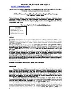
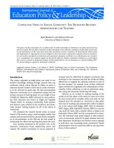
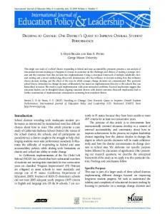
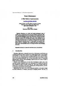
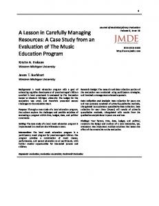
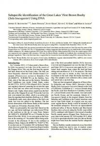
The work described in this paper was performed within the framework of the Tempus e-Sience project (EuroMaghribeen project financed by the European community) in which the university, Constantine1, is a partner. The main objective of this project was the use of new technologies to develop e-Learning in the electrical engineering field, especially the implementation of remote labs for experimental work. A. Hardware Part In this part, the design of an interactive network structure is represented. This structure allows students to supervise and control the temperature in an experimental system using a PID controller. This architecture allows the students to change the desired temperature value and the PID controller parameters during the experiment from any terminal connected to the Intranet or Internet network. Different kinds of network architectures can be used for an iLab [5]. The proposed network architecture is represented in Fig. 1, and the system used for this experiment is shown in Fig. 2. It is composed of a temperature measurement system, an acquisition card and a server. All these parts are connected according to the control loop given in Fig. 3. The block diagram shows a closed loop control system. The measured temperature is compared with a reference value. The difference between these two values is processed by a PID controller, which initiates actions to drive the difference signal toward zero. Supervision and control of the system output are performed through a graphical user interface (GUI) developed in the Lab server.
Figure 1. Online lab architecture
22
http://www.i-jim.org
SPECIAL FOCUS PAPER ONLINE TEMPERATURE CONTROL SYSTEM III.
TEMPERATURE CONTROL REMOTE EXPERIMENT
The temperature subsystem is involved in many everyday life systems such as air conditioning units, irons, electric ovens and many other industrial systems [7]. The proposed remote experiment concerns a temperature system control. The heat is generated by thermal resistance.
Figure 2. Online lab architecture
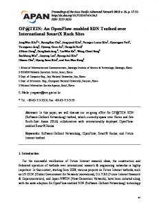
A. Remote Experiment Objectives The aim of the experiment can be summarized in three objectives, which constitute the student work steps: • Temperature system identification from experimental data. • Open-loop Ziegler-Nichols PID tuning and test of the temperature system. • Closed-loop Ziegler-Nichols PID tuning and test of the temperature system. B. Preparing the Practical Work Before the physical remote experiment, the students are provided with experimental data obtained from a step response of the temperature system. The students are asked to plot the system time answer and to confirm its Sshape. The expected curve is shown in fig. 4. Once the curve is obtained and plotted, the students should identify the parameters of a first-order delayed system: static gain K, time constant !!and delay !! . The transfer function of the model is the following form [8]:
Figure 3. Experiment block diagram
B. Software Part The acquisition card used in this work is a NI-6008 card, which is compatible with the LabVIEW development environment [6]. Therefore, this environment is used for data-acquisition, remote monitoring, and control of different experiment parameters via a GUI. We noticed that the LabVIEW environment can control experiments connected to the Intranet or the Internet network in real time using LabVIEW webserver. It also offers the possibility of controlling experiments remotely from a web browser. In this case, the only required software for the remote clients is the LabVIEW Runtime Engine, which can be downloaded freely from the National Instruments website. As exhibited in Fig. 1, this environment has a lab server that manages the experiment and a web server that handles client access. Real time remote monitoring and control are effectuated by using the LabVIEW web-publishing tool. In this case, the developed VI (Virtual instrument) is accessible on the local or the Internet network via web browsers. To access the VI remotely, the IP address of the server and the name of the shared VI should be known by the remote client. At the same time, the published VI must always be running on the Lab server. The remote user regains control of the experiment only after requesting and receiving acceptance from the server. During the experiment, the students can start and stop the program execution whenever they want. They can change the desired temperature value and the PID controller parameters at any time. Moreover, it is also possible to store all the experiment results data from the graph in "spreadsheet" format.
iJIM ‒ Volume 9, Issue 2, 2015
! ! !
!!!!!!
(1)
!!!!
C. Remote Experiment Content The experiment content can be divided into two parts: Open-loop and closed-loop PID tuning and test. 1) Open-loopZiegler-Nichols PID tuning and test: Once the experimental model is obtained during the student preparation, a PID controller is directly obtained using Ziegler-Nichols rule for an open-loop identified system [8]. The parameters Kp, Ti and Td are a function of the answer curve slope a and the model delay!! . From the users’ side, the remote students have an interface to directly introduce the PID parameters and to make a real remote test on the physical system via a web browser. This interface allows the students to follow the regulated physical system response on the web browser in real time. The student has to do an analysis to adjust the true parameters if a wrong result is obtained as saturation or overshoot. The student interface is shown in Fig 5. For both open and closed loop cases, the implemented controller on the measurement server using LabVIEW has the following transfer function ! ! ! !! ! !
!
!! !
! !! !
(2)
2) Closed losed-loop Ziegler-Nichols PID tuning and test: For the closed loop case, the process to be controlled is put in a closed loop with a variable gain K0. As shown in Fig 6, the gain is tuned until the system starts to oscillate. The value of K0 causing the start of oscillation and the oscillations period T0 are then used to tune the three PID parameters [8].
23
SPECIAL FOCUS PAPER ONLINE TEMPERATURE CONTROL SYSTEM
Figure 4. Open-loop answer of a delayed first order system
Figure 7. Temperature system response with PID parameters tuned from ZNOL.
Figure 5. Student interface to tune the PID controller.
Figure 6. Oscillating closed-loop response with proportional action.
IV.
Figure 8. Temperature system response with PID parameters tuned from ZNCL
EXPERIMENT RESULTS
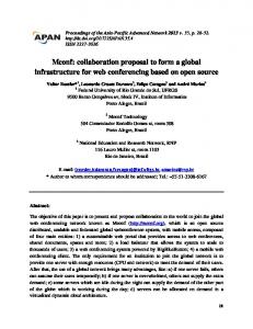
To illustrate the performance of the experimental lab described in this paper, the effect results of different PID parameters on the system response have been investigated. Fig. 7and Fig. 8 represent the temperature system responses when the PID parameters are tuned from the Zeigler-Nichols open loop (ZNOL) and closed loop (ZNCL) methods, respectively. The interface that controls the system via a web browser is shown in Fig. 9. V.
CONCLUSION
An online remote temperature control system is proposed for educational purposes. A simple web browser is used by the students to access the physical experiment. Experimental Ziegler-Nichols tuning rules for a PID controller were tested in real time. The control system was successfully tested online. As a perspective, an iLab shared architecture will be used to share the experiment on the Internet network.
24
Figure 9. Graphical user interface as displayed on remote client web browser.
http://www.i-jim.org
SPECIAL FOCUS PAPER ONLINE TEMPERATURE CONTROL SYSTEM REFERENCES [1] [2] [3]
[4]
[5] [6] [7] [8]
T. A. Fjeldly and M. S. Shur, LAB ON THE WEB Running Real Electronics Experiments via the Internet. Wiley-interscience, 2003. http://dx.doi.org/10.1002/0471727709 A. Leva and F. Donida, “A remote laboratory on PID autotuning,” Proc. 17th IFAC World Congress. Korea, pp. 8147-8152, July 2008. B. Aktan, C.A. Bohus, L.A. Crowl, and M.H. Shor,“Distance learning applied to control engineering laboratories,” IEEE Transactions on Education, Vol. 39, pp. 320–326, 1996. http://dx.doi.org/10.1109/13.538754 P. H. Wu and C. H. Kho, “The design and implementation of a remote automatic control laboratory: using PID control as an example,” Tamkang Journal of Sience and Engineering, Vol. 11, pp. 219-228, 2008. V. Judson et al, “The ilab shared architecture: a web services infrastructure to build communities of internet accessible laboratories,” Proceeding of IEEE, Vol. 96, No. 6, pp. 930-951, June 2008. LabVIEW software platform, URL: http://www.ni.com/labview. P. Zhang, Advanced Industrial Control Technology. 2010. G. F. Franklin, D. J. Powell, and A. Emami-Naeini, Feedback Control of Dynamic Systems. Prentice Hall, 2002
AUTHORS A. Ikhlef is with Universités de Constantine, Laboratoire d’Automatique et de Robotique, Faculté des sciences
iJIM ‒ Volume 9, Issue 2, 2015
de la technologie, Université Constantine 1, Algérie (email:
[email protected]). M. Kihel is with Universités de Constantine, Laboratoire Micro-systèmes et Instrumentation, Faculté des sciences de la technologie Université Constantine 1, Algérie (e-mail:
[email protected]). B. Boukhezzar is with Universités de Constantine, Laboratoire d’Automatique et de Robotique, Faculté des sciences de la technologie, Université Constantine 1, Algérie (e-mail:
[email protected]). A. Guerroudj is with Universités de Constantine, Laboratoire d’Automatique et de Robotique, Faculté des sciences de la technologie, Université Constantine 1, Algérie (e-mail:
[email protected]). N. Mansouri is with Universités de Constantine, Laboratoire d’Automatique et de Robotique, Faculté des sciences de la technologie, Université Constantine 1, Algérie (e-mail:
[email protected]). This project has been funded with support from the European Commission. This publication reflects the views of only the author, and the Commission cannot be held responsible for any use which may be made of the information contained therein. Submitted 15 January 2015. Published as resubmitted by the authors 23 March 2015.
25