Aug 4, 1999 - Foundation. 1 trigger decision, and are used for online identification of ..... chips are 50,000 gate equivalent devices made by Altera. Corp., and ...
University of Nebraska - Lincoln
DigitalCommons@University of Nebraska - Lincoln Kenneth Bloom Publications
Research Papers in Physics and Astronomy
8-4-1999
Online Track Processor for the CDF Upgrade C. Ciobanu Ohio State University
J. Gerstenslager Ohio State University
J. Hoftiezer Ohio State University
R. Hughes Ohio State University
M. Johnson Ohio State University See next page for additional authors
Follow this and additional works at: http://digitalcommons.unl.edu/physicsbloom Part of the Physics Commons Ciobanu, C.; Gerstenslager, J.; Hoftiezer, J.; Hughes, R.; Johnson, M.; Koehn, P.; Neu, C.; Sanchez, C.; Winer, B.L.; Freeman, J.; Holm, S.; Lewis, J.D.; Shaw, T.; Wesson, T.; Bloom, Kenneth A.; Gerdes, D.; Dawson, J.W.; and Haberichter, W.N., "Online Track Processor for the CDF Upgrade" (1999). Kenneth Bloom Publications. 104. http://digitalcommons.unl.edu/physicsbloom/104
This Article is brought to you for free and open access by the Research Papers in Physics and Astronomy at DigitalCommons@University of Nebraska Lincoln. It has been accepted for inclusion in Kenneth Bloom Publications by an authorized administrator of DigitalCommons@University of Nebraska - Lincoln.
Authors
C. Ciobanu, J. Gerstenslager, J. Hoftiezer, R. Hughes, M. Johnson, P. Koehn, C. Neu, C. Sanchez, B.L. Winer, J. Freeman, S. Holm, J.D. Lewis, T. Shaw, T. Wesson, Kenneth A. Bloom, D. Gerdes, J.W. Dawson, and W.N. Haberichter
This article is available at DigitalCommons@University of Nebraska - Lincoln: http://digitalcommons.unl.edu/physicsbloom/104
IEEE TRANSACTIONS ON NUCLEAR SCIENCE, VOL. 46, NO. 4, AUGUST 1999
933
Online Track Processor for the CDF Upgrade C. Ciobanu', J. Gerstenslager', J. Hoftiezer', R. Hughes', M. Johnson', P. Koehn', C. Neu', C. Sanchez', B.L. Winer', J. Freeman', S. Holm', J.D. Lewis', T. Shaw2,T. Wesson', K. Bloom3, D. Gerdes3, J.W. Dawson4, W.N. Haberichter4 'The Ohio State University, 'Fermi National Accelerator Laboratory, 3University of Michigan, 4Argonne National Laboratory
Abstract A trigger track 'processor is being designed for the CDF upgrade. This processor identifies high momentum (PT > 1.5 GeV/c) charged tracks in the new central outer tracking chamber for CDF 11. The track processor is called the extremely Fast Tracker (XFT). The XFT design is highly parallel to handle the input rate of 183 Gbits/sec and output rate of 44 Gbitslsec. The processor is pipelined and reports the results for a new event every 132 ns. The processor uses three stages, hit classification, segment finding, and segment linking. The pattern recognition algorithms for the three stages are implemented in programmable logic devices (PLDs) which allow for in-situ modification of the algorithm at any time. The PLDs reside on three different types of modules. Prototypes of each of these modules have been designed and built, and are presently undergoing testing. An overview of the track processor and results of testing are presented.
I. INTRODUCTION The CDF collaboration is currently upgrading the CDF detector for the next p p collider Run 11, scheduled to start in early 2000. The upgrades are substantial, ranging from a complete replacement of all of the charged tracking detectors, extension of the muon coverage, and replacement of the plug and forward calorimetry. In addition, the data aquisition systems are undergoing almost complete replacement. The purpose of these upgrades is to both handle and take advantage of the new Tevatron running conditions planned for Run 11. The Tevatron upgrades will bring approximately an order of magnitude increase in the instantaneous luminosity, and the detector upgrades will yield a large increase in acceptance, particularly for those analyses dependent on central tracking. This will greatly extend the physics reach for CDF, providing a unique opportunity to probe the standard model in great detail. The extremely Fast Tracker (XFT), is a trigger track processor that identifies charged tracks in CDF's new Central Open Tracker. The tracks are found in time for the Level 'We thank the Fermilab staff and the technical staffs of the participating institutions for their vital contributions. This work was supported by the US. Department of Energy and National Science Foundation; the Italian Instituto Nazionale di Fisica Nucleare; the Ministry of Education, Science and Culture of Japan: the Natural Sciences and Engineering Research Council of Canada; the National Science Council of the Republic of China: and the A.P. Sloan Foundation. 0018-9499/99$10.00
1 trigger decision, and are used for online identification of electrons and muons. This trigger is at the heart of much of the physics that CDF hopes to do in Run 11. The XFT is needed to identify high momentum leptons for top, electro-weak, and exotic physics. It is needed for identification of low-momentum charged tracks for B physics analyses. Without this device the physics potential of CDF I1 would be severely compromised.
11. CDF I1 UPGRADE The goal of Tevatron Run I1 is the accumulation of of 2 fb-' at = 2.0 TeV, using luminosities of up to 2 x 1032~m-2s-1.This represents a factor of 20 increase in the expected data sample size over what CDF accumulated during Run I. The luminosity increase is a factor of 10 over the maximum experienced during Run I and is made possible by both the new Main Injector, as well as the anti-proton recycler [l]. To keep the number of overlapping interactions per crossing at a manageable level, the Tevatron will increase the number of proton and antiproton bunches in the machine to 108 (from 6 used in Run I), while decreasing the time between bunches to 132 nsec (from 3.5 psec used in Run I). This new time structure requires major changes to the data aquisition and trigger systems, as well as replacement of the central tracking chamber.
6
The upgrades to CDF are extensive, and are documented in detail elsewhere [2]. The specific parts of the upgrade relevant for this paper are the following: The Central Outer Tracker (COT) The COT is a open cell drift chamber for charged particle reconstruction, occupying the radial region from 44 to 132 cm. The COT replaces the Central Tracking Chamber(CTC), which in addition to aging problems observed during Run I, would also suffer from degraded performance at L 2 1 x io3' crr-' s . The basic problem with the CTC is its maximum drift time (800 ns) relative to the expected bunch crossing time in Run I1 (132 nsec). To address this, the COT uses small drift cells ( w 2 cm wide - a factor of 4 smaller than the CTC) and a fast gas to limit drift times to less than 130ns. Eachcell consists of 12 sense wires oriented in a plane, tilted at approximately 35' with respect to the radial. A group of such cells at a given radius is called a superlayer. There are 8 alternating superlayers of stereo (nominally an angle of 3') and axial 0 1999 IEEE
934
silicon vertex trigger (SVT) processor. This will result in an improved determination of the track momenta, as well as identification of tracks displaced from the primary vertex, a first for a hadron-collider experiment.
wire planes. Trigger and Electronics Just as in Run I, CDF will employ a 3 Level trigger system in selecting events to write out to mass storage. Each successive level in the trigger applies more stringent selection criteria, in order to eventually reach the Level 3 output rate of < 50 Hz. With only 132 nsec between bunches, the Level 1 trigger electronics needs to be pipelined, so that there is enough time to make a decision on whether to pass the event onto Level 2. In addition, due to the factor of 10 increase in luminosity expected in Run 11, the rejection rate of the trigger will also have to increase by almost a factor of 10.
111. THEXFT TRACKPROCESSOR In Run I, tracks were identified in the CTC in time for the Level 2 decision by the Central Fast Tracker (CFT) [3]. The processing time for the CFT was approximately 10 psec, and was strongly dependent on the complexity of the event. Due to the much smaller bunch crossing time, and the need to move track identification into the Level 1 trigger decision (more on this below), a new track processor, the extremely Fast Tracker (XFT),is needed.
4. Finally the Level 3 trigger reduces that rate to 5 50 Hz, at which point accepted data are transferred to permanent storage media. The Level 3 trigger is actually a farm of CPUs, running a version of the offline reconstruction software. The performance of the Level 3 trigger is set by how quickly it can process events. In Run I, the software track reconstruction algorithm was responsible for about 50% of the processing time for the Level 3 trigger. Since the COT has 4 times as many cells as the Run I tracking chamber, the situation will only be more difficult for Run 11. The XFT can contribute here as well. The XFT will provide the location of valid segments in all 4 axial layers (more on this below), and so could provide a seed for the Level 3 tracking algorithm, speeding the processing time up substantially.
RUN I1 TRIGGER SYSTEM Detector Elements
~~~~p~
I
A. Role of the XFT in the Trigger The purpose of the full trigger system is to identify the subset of “interesting” physics events, reducing the raw collision rate from 7.5 MHz to a rate at which events can be stored for further offline analysis. The XFT plays a major role in this reduction, primarily in the first two levels of the trigger, but is also suited to play a significant role in the Level 3 trigger. Block diagrams of the Level 1 and 2 trigger system and the Run I1 readout dataflow are shown in Figures1 and 2. The steps from a p p crossing to writing events to offline storage can be summarized as follows: 1. The bunch crossing rate is 7.5 MHz. This corresponds to a p p crossing every 132 nsec. For an instantaneous cm-2 s one expects an luminosity of 2.0 x average of 2 p p interactions every crossing.
-’
2. The L1 trigger needs to reduce this rate to less than 5OkHz. This assumes a Level 2 processing rate of 20 p e c , and results in a deadtime of 5 10 %. The primary purpose of the XFT is to identify tracks in the COT in time for the Level 1 decision. The XFT tracks at Level 1 are matched to electromagnetic-calorimeter clusters for electron identification, to stubs in the muon system for muon identification. The tracks are also used in a two-track trigger for events such as B --t ?T+T-.
3. The Level 2 trigger needs to reduce the Level 1 rate down to 5 300 Hz. This rate is set by the processing capability expected for the Level 3 trigger. To help accomplish this rate reduction, the XFT tracks will be linked to hits in the silicon vertex detector by a separate device called the
v
I
v
I
xFT
MUON PRIM.
I
v
XCES
Irnl / I
&rHp, CAL
LEVEL 2
FIW 9mm
Figure 1: The Run I1 trigger system block diagram. The X R system can be seen in the 2nd row from the top.
B. Requirements on XFT Performance Based on these considerations, we have set the following minimum design specifications: For the reasons discussed above, the XFT will need to be pipelined, and will need to present a new set of found . .
935
I L
Dataflow of CDF "Deadtimeless" Triaaer and DAQ
--
I
I
C. XFT Algorithm Overview The XFT processor works off of hit data from the 4 axial superlayers of the COT. As mentioned earlier, the superlayers are arranged in cells of 12 wires each, oriented at an angle of 30' relative to the radial. There are a total of 16,128 axial wires, and the data on each wire are classified as prompt and/or delayed, for a total of 32,256 bits of information. A charged track passing through an axial superlayer will generate 12 "hits" of prompt and/or delayed data. The definition of a prompt or a delayed hit will depend upon the maximum drift in the COT. For a bunch spacing of 132 nsec, the maximum drift is 121 ns, and so a prompt hit occurs whenever there is a hit in the time window 0-44 ns, and a delayed hit is defined as a hit falling in the window 44-121 ns. N
L1 storage Plpllne: 42 Clock cycles Deep
t50 kHz Accept ram
Arync. 2 stage plpeline
L2 Bunan: 4 Events
[
s~::e
J
PJW 1 0 n W
Figure 2: The Run I1 readout block diagram with the expected rejection of the trigger system at each level. tracks every 132 nsec. The results must be ready in time for the Level 1 trigger decision, which means the XFT will need to find tracks in less than 1.5 psec. For physics analyses such as top, electroweak studies, and searches for new phenomena, high efficiency is critical. We set a goal that the XFT track-finding efficiency will be greater than 96% when the single-hit efficiency of the central tracker is greater than 92%. The momentum resolution reported to the trigger will be APT/P$ < 1.5%/GeV/c. In Run I, the track processor 3.5%/GeV/c. momentum resolution was AP,/P$ Better momentum resolution allows a lower threshold at high PT,which in turn increases acceptance.
N
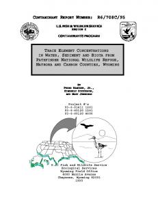
Track identification is accomplished in two processes the Finder and the Linker. The Finder searches for high-PT track segments in each of the outer-four axial superlayers of the Central Tracker. The Linker searches for a four-out-of-four match among segments in the 4 layers, consistent with a prompt high-PT track. If no track is found, the Linker searches for a three-out-of-three match among segments in the innermost 3 layers. An example of a 1.5 GeVk track traversing the COT is shown in Figures 3 and 4. 150 I
100
50
0
kV/C
k
-50
N
The resolution on the extrapolated 4 position at the origin (a#,) should be better than 8 mrad. This is set by the requirement that X F I tracks will be used in the Level 2 trigger and attached to hits in the silicon vertex detector. The fraction of tracks found by the XFT which are not associated with a real track (i.e. fakes) should be less than 10% for PT 2 10 GeV/c. This fake-trackrejection is also needed to reduce the high-PT muon trigger rate at high luminosity. The minimum track PTwill be 1.5 GeV/c. In Run I the minimum PT was 2.2 GeV/c. The cut-off at 1.5 GeVk is set by the fact that muons range out in the calorimeter for track momenta below this. In addition, a lower PTcutoff allows greater acceptance for B decays that can be used to measure CP violation.
-100
-150
-150
" " ' ' " ' " " ' ' " ' 1 " ' " " ' ' -100
-50
50
100
>
Figure 3: A schematic drawing of a track with Pt = 1.5 GeV/c in the COT. The figure depicts the four axial superlayers. Only every 4th cell is shown in each layer. The dashed curves represent the layers of silicon inside the COT.
D. The Finder The Finder is designed to look for valid track segments in a given axial superlayer. To do this quickly, each COT superlayer is divided into groups of four cells each, with each group processed by a single Finder PLD as shown in the Figure 4. Within a given layer, the design and operation of the PLD are all identical. The PLDs compare hit data to a predefined set of patterns, and all of the patterns are searched over simultaneously.
936
FINDEE 15
Layer 2
Loyer 1
, , , , I, , , , I , , , , ,
-15b , , , , , , , , , , , , , , / , , , , , , , ( , ,,,, I
50
60
70
a0
Layer 4
Layer 3
110
100
90
120
130
140
Figure 4: The above figure shows a close up of the track in Figure 3. All cells in all four axial layers are shown, and the relevant Finder in each layer is highlighted.
Loye, 1
Layer 2
Layer 3
Layer 4
10
5
0
R -5
-10
-2
yy I
/
124
'
"
126
" '
128
-15 ,
"
'
I
b,, 50
"
"
130
'
I
"
' I 132
'
,11,, , , I , , 60
70
,,I , , , , 80
I , ,
90
,
,, ,,,, 100
110
,,
I , ,
120
,,
I , ,
130
,,
,
140
134
Pigure 5: A closeup of a track with Pt = 1.5 GeV/c in the 4th axial superlayer. The wires marked by the diamonds are those with "delayed" hits, while the wires marked with open circles are those with "prompt" hits. The collection of prompt and delayed hits on the given wires is an example of a mask.
A track segment is defined by the cell and whether a prompt or delayed hit was generated in each of the 12 wire planes within a superlayer. A collection of the cell numbers and hit types for the 12 wires in an axial layer is called a mask. Examples of two masks are shown in Figures 5 and 6. The mask will change depending on the 4 of the track, and its angle through the cell (or PT). The Finder works by storing all possible masks for tracks with PT 2 1.5 GeV/c in a database (or equivalently, hard wired on a chip). The mask set is determined for a given axial superlayer by a Monte Carlo
Figure 7: A closeup of the track from Figure 3, but now showing the Linker the track should be found in. Also shown are all of the pixels needed by this Linker. program. Since all of the cells in a given layer are identical, only one set of masks is needed for each layer. Due to the fact that for a given PT, the local slope is greater in the outer layers than in the inner layers, the outer layers will require a larger mask set than the inner layers. The inner layers 1 and 2 and the outer layers 3 and 4 require 173, 242, 290, and 337 masks respectively. The Finder compares incoming TDC information with all masks for the given axial superlayer, allowing a programmable (up to 3) number of missed wire planes.
In the inner two axial layers, valid segments are characterized by 1 of 12 pixel positions across the midpoint of the cell. In the outer two axial layers, valid segments are characterized by 1 of 6 pixel positions across the midpoint of
937
the cell, and 2 bits of slope information. These two bits are characterized as follows: e
00 = no mask found 01 = negative low Pt track segment
e
10 = positive low Pt track segment
e
11 = high Pt track segment (nominal PT 2 8 GeV/c)
The pixel bin size is approximately 1.5mm in the inner two layers, and approximately 3.0mm in the outer two layers. Every 132 nsec the Finder outputs 12 bits per cell (12 pixels for the inner two layers, 6 #J pixels x 2 slopes for the outer two layers) to the Linker. The Finder outputs all pixels corresponding to a valid track pattern - not just the pixel position of the best segment. #J
To reduce the total number of Finders, each Finder chip identifies segments for 4 adjacent COT cells. There will be only one set of masks stored per layer, and the inputs from the 4 separate cells will be multiplexed. The total number of Finder chips needed is then 336. The Finders will be implemented using in-system reprogrammable logic chips. The Finder system takes in 2 bits of information for each of 16,128 axial wires every 132 nsec, and output a total of 12 bits for each of 1,344 cells every 132 nsec.
E. The Linker The Linker is designed to look for valid tracks which cross either 3 or 4 axial superlayers. The input is the pixel and slope information transferred from the Finders. To locate tracks quickly, the COT is divided into 288 identical #J slices, each of which is processed by a single Linker chip. The Linker chips will also be implemented using in-system reprogrammable logic chips. The chips compare pixel and slope data to a predefined set of patterns, and all of the patterns are searched over simultaneously. Each Linker chip is given all of the pixel information needed to find the tracks in a A#J = 1.25" phi-slice of the tracking chamber. Due to track curvature, a significant fraction of the pixels needed to identify all tracks that key off the 3rd axial layer come from outside of the A#J= 1.25' phi-slice. This is shown in Figure 7. The Linker algorithm begins by searching (in parallel) a list of about 2400 roads, where a road is a group of 4 pixels, one from each axial superlayer, corresponding to a valid track with PT 2 1.5 GeV/c. The pixels in the outer 2 axial layers are required to have the same sign of PT as the Linker track. The roads are defined by their PT and the pixel position in layer 3. The roads are then "or"ed together resulting in 96 PT bins and 8 pixel locations. Found tracks are passed through a priority encoder to find the best track in the 1.25' region covered by the Linker. The information reported on the best track is 7 bits of PT, 3 bits of 4, 1 bit indicating whether the track is isolated, and 1 bit indicating whether the track used 3 or 4 layers. If no track is found using all 4 layers, then the best track found in the innermost 3 layers is output. This allows a small increase in the rapidity coverage of the XFT.
F: XFT System Hardware I ) Overview The System hardware begins with the mezzanine module residing on the COT TDC's in the CDF collision hall. This module will classify the hits on the COT wires as prompt or delayed and send that information to a transition module at the back of the COT TDC crate. The transition module drives the data at 45.5 MHz, with Low Voltage Differential Signal (LVDS) technology, onto Level 1 Trigger cables that carry the COT wire data 220 ft to the Finder module crates. Finder transition modules receive the data and send it across a customized backplane to the Finder modules. Finder modules find track segments and report them to the Linker modules. Transition modules drive found track information from the Linker modules to the XTRP (see Figure 1). Listed below are the essential elements that compose the Finder and Linker modules. 2 ) Finder Modules The Finder portion of the XFT system consists of two types of modules: the SL13 for COT axial superlayers 1 and 3, and the SL24 for superlayers 2 and 4. Each type of Finder module searches for track segments in a 15" region of 4. There are 24 SL13 and 24 SL24 modules housed in 3 9U x 400mm VME [4] crates (8 of each module type per crate). Each crate has a commercial VME-based processor (VME-CPU) that controls communication via VMEbus. All Finder modules have Input Alignment PLDs that latch and align the COT wire data received from the Level 1 Trigger cables and send it to the Finder PLDs at 30.3 MHz. SL13 modules contain 2 superlayer 1 PLDs and 4 superlayer 3 PLDs. SL24 modules contain 3 superlayer 2 PLDs and 5 superlayer 4 PLDs. In addition to the track segment finding algorithm, the Finder PLDs hold the Level 1 pipeline and the Level 2 data buffers for found pixel and COT hit information. The Finder PLDs report the found pixel data to a set of PLD's called the Pixel Drivers that duplicate this information, and send it to LVDS drivers (National DS90CR281/282 28-bit Channel Links). The data l m of cabling to the Linker modules at 30.3 is driven over MHz. A dedicated PLD on each Finder module provides the VMEbus slave interface. Clock circuitry generates on board 33 nsec, 66 nsec, and 132 nsec clocks derived from the Master CDF clock feeding silicon delays. The Finder module also contains: RAM for loading PLD designs, circuitry for allowing boundary scans of all PLDs, and ports for loading PLDs from a serial port of a PC. N
3) Linker Module The Linker portion of the XFT system contains 24 9U modules in 3 crates @/crate). Each Linker module covers a 15' region of 4. Track segment information from the Finder modules are captured at LVDS receivers (National Channel Links DS90C031) on the Linker module. Six Input Formatting PLDs latch the data from the Channel Link receivers and synchronize the data with the on board 33 nsec clock. The 6th Input Formatter performs error checking at the input. There are 12 Linker PLDs that receive data at 30.3 MHz from the
938
Input Formatters, and search for the best track. Each Linker PLD covers a region 1.25” in 4. The Linker PLDs transmit data at 7.6 MHz to 2 Output Formatter PLDs. Here the data is reformatted and passed through to a transition module that drives (LVDS) the data over 50 ft of cabling to the XTRP. A VME-Control PLD contains the functionality for the VME slave interface, a state machine that controls the response to trigger signals, and the loading of all the PLD designs on the module. As with the Finder, the Linker module also contains: on board clock generation from the Master CDF clock, RAM for loading PLDs, PLD boundary scan circuitry, and ports for external loading PLDs. N
G. XFT Prototype testing Prototype modules for the Finder and Linker portions of the XFT have been built. The testing of these modules has been factorized into separate pieces of the full XFT system. Each module type is tested singularly and in conjunction with testboards that take the place of the missing XFT or other trigger system module types upstream and/or downstream in the system chain. As the separate pieces of the XFT are successfully tested they are added to the chain to create a fully operational slice of the XFT system. Below we list the basic components used and describe the types of tests performed with the XFT prototypes. 1 ) XFT Teststand Components The prototype modules for the Finder and Linker are housed in VME crates that contain a VME-CPU. The source of 132 nsec clock used to drive all the modules in the XFT teststand is called the Testclock module. The Testclock emulates the CDF Master clock and Trigger Supervisor Interface providing the Level 1 and 2 trigger control signals. This allows for testing the XFT in a simulated CDF data taking environment. An essential tool in the hardware testing is a full simulation of the entire XFT system. With this hardware simulation, interconnects and the states of latched registers may be checked throughout the system. Input data files and output reference files are generated by this simulation for verifying the operation of the XFT. 2 ) Testing Scheme The basic testing scheme, implemented in both the Finder and Linker subsystems, begins with the downloading simulated data over VMEbus to the Finder, Linker or testboards, upstream in the system. Next, the teststand is set into operation by responding to simulated CDF trigger control signals generated by the Testclock. All modules in the system run at their nominal speed as they would in the CDF data taking environment. Finally, the output is captured and read out (via VME) in the Finder, Linker, or testboards downstream and checked against data files from the hardware simulation. 3) Finder Prototype
To test the track segment finding algorithm for single Finder modules, the Input Alignment and Pixel Driver PLDs are reprogrammed to act as input and output RAM respectively. Simulated events of prompt and delayed COT hit information
produced from the Finder mask database are downloaded to the input section. This data is processed by the Finder PLDs at speed, and the found track segments are captured in the output RAM. The Finder’s ability to capture and process data transmitted at 45.5 MHz from the frontend COT TDC’s over 220 ft of Level 1 Trigger cabling is tested in the following setup. Simulated data is downloaded to RAM on testboards that send the information to a TDC transition module that drives the data, up the Level 1 Trigger cables. A Finder transition module receives the data from the Level 1 Trigger cables (this cabling was used in CDF Run I and will be used in Run 11) and passes the information to the Finder module. There the data is either latched at the Input Alignment section and read out, or sent on for processing by the Finder chips and read out at the Pixel Drivers reprogrammed as Ram. To test data transmission out of the Finder, a testboard containing l k deep FIFO chips is used to capture the pixel data output sent from the Finder module. The Input Alignment section (reprogrammed as RAM) of the Finder module are downloaded with simulated data which is processed by the Finder PLDs and the found pixels are passed to the Pixel Driver chips. From there the data is sent via the Channel Links to the testboard. In the test configurations described above, we verified the Finder module’s ability to latch and align simulated input events, locate the expected track segments, and pass on the correct output information with the proper timing. 4 ) Linker Prototype
The Linker portion of the XFT teststand consists of a Linker module and a testboard that is essentially made up of input driving FIFOs and output receiving FIFOs. In this setup, the driving FIFOs of the testboard take the place of Finder modules. The receiving FIFOs take the place of the XTRP. To test the operation of a full Linker module, pixel information produced from the Linker road list or simulated physics events is downloaded to the input driving FIFO’s on the testboard. The data is sent out the front panel via Channel Links at 30.3 MHz and received at the input formatting section of the Linker module. The Linker PLDs process the data and the resultant found track information is passed to the Output 50 Formatting chips. The reformatted data is driven over feet of cable, returning to the testboard where it is captured (at the rear of the crate) in the output receiving FIFOs and checked. N
By reprogramming the input and output formatting PLD’s on a singular Linker module as RAM, the track segment linking algorithm can be isolated and tested as described above for a singular Finder module. Further reprogramming the Linker PLD’s to merely pass the input data directly through to the output, and running the module at speed, the timing and integrity of the module data flow may checked. In the above test configurations, we have successfully verified the Linker’s ability to capture, propagate data, find expected tracks, and to pass on tracking information with the
939
proper timing. Testing has been performed with input data consisting of simulated physics events and track segments generated from the Linker road list.
5) Finder to Linker Integration Testing the Finder and Linker modules operating together, exercizes the heart of the XFT trigger. The setup has 1 Linker module receiving pixel data over Channel Links from two Finder modules: a SL13 and a SL24. The Input Alignment PLDs (reprogrammed as RAM) of the Finder modules are downloaded with the appropriate COT hit data from simulated physics events. Both modules start, process data at speed, and halt in response to trigger control signals issued from the Testclock. The Finder and Linker modules successfully located track segments, found, and reported the hest track in an event. Moreover, the Level 1 pipeline and Level 2 buffers of the Finder and Linker modules were properly synchronized so that they reported information from the same event.
H. XFTStatus A very brief list of the milestones of the project include the following: 1. A functional simulation of the XFT has been written to both develop and test the XFT algorithm. The results of the simulation are shown in Table 1 and are compared to the specifications outlined above. The present design meets the specifications in all respects. 2. Both the Finder and Linker algorithms have been implemented using programmable logic chips. These chips are 50,000 gate equivalent devices made by Altera Corp., and allow full in-system reprogrammability. Both designs have been fully simulated for both timing
(ability to run at 33 ns or faster) as well as accuracy of results (verified against the functional simulation). 3. Prototypes of the Finder and Linker modules are currently being tested.
4. Production module testing is planned for the spring of 1999.
5. Installation of the XFT at CDF will begin by mid-summer 1999.
6. Real data (collisions) taking is planned for April of 2000. Table 1 X l T performance using the functional simulation. The luminosity for this simulation corresponds to 2.0 x c ~ - ’ s - ~at 132 nsec Parameter Efficiency Muon Trigger rate Percentage Fakes
bunch spacing. I Specification
I
296% 5 50 Hz 5 10%
Simulation 96%
30 Hz
1.2% 0.8 E&
4mRad
IV. REFERENCES
~. 111 S. D. Holmes, Status of the Fermilab Main Injector and
Recycler, Fermilab-Conf 97/298. [2] The CDF-I1 Detector: Technical Design Report, The CDF 11 Collaboration, Fermilab-Pub 96/390 E. [3] G.W. Foster, J. Freeman, C. Newman-Holmes, and J. Patrick, A Fast Hardware Track-Finder for the CDF Central Tracking Chamber, Nucl. Instr. and Meth. A268 (1988) 33. [4] VME International Standards Organization, Scottsdale, Az.