Due to proprietary reasons, the operating system running on this PC is VxWorks (Wind-. River, 2005), which allows easy integration of many commercially ...
18 Open Software Architecture for Advanced Control of Robotic Manipulators J. Gomez Ortega, J. Gamez García, L. M. Nieto Nieto and A. Sánchez García
System Engineering and Automation Department at Jaén University, Spain 1. Introduction
So far, the robotic applications has been dominated by proprietary based hardware and software devices developed for industrial applications with a large volume manufacturing, like the automotive and electronics industries. Then, the main goal of the automation technologies has been an optimized robot design for precise assembly tasks, resulting in complex systems with a reduced flexibility. Traditional robotic applications have a fixed configuration, with the advantages of high accuracy and a well studied kinematics. However, since recent years, the number of service robots in our daily life environments is increasing. There are many new applications, i.e. teleoperation, human-robot-collaborative works, etc. that require reconfigurable hardware and expansibility to accomplish new working modes in not-structured scenarios and notintensive manufacturing tasks. However, these systems must meet diverse user requirements and integrate different hardware and software systems developed for a particular proprietary platform. As a result, many different researchers have solved similar issues with non-interchangeable products, working from scratch each time, adapting the traditional industrial robots platform for the new applications. Today, a new robotic system is an integration of different processors and hardware platforms manufactured by different vendors, controlled by software modules developed using different programming languages and different communication protocols. In addition, as robotic manipulator is expected to accomplish more complex tasks, it needs the integration of multiple sensors working with different time bases and bandwidths (Gamez et al., 2009; Luo et al., 2002), and new capabilities are needed that traditional control technology of current industrial robots is not offering. In order to solve these problems different open robotics platforms have been presented. 1.1 Open robotic platforms: an overview From the definition of an Open Systems (IEEE 1003.0), an Open (Robotic) Platform should "provide capabilities that enable properly implemented applications to run on a variety of platforms from multiple vendors interoperate with other system applications and present a consistent style of interaction with the user". This leads to the following properties: • Portability of the software, to reuse it in other platforms with minor changes.
382
Advanced Strategies for Robot Manipulators
•
Reusability is an issue that should be addressed from the beginning of the development process, identifying common problems that could be solved with reusable solutions and shared within the robotics community. • Extensibility to change or add several component (of hardware or software) to the system from different vendors. • Adaptability/dynamic reconfigurability, providing mechanism of easy adaptation of its parameters according to the application requirements. • Interoperability refers to the ability to support interchange of information between robotic modules designed by different vendors, providing effective communication and working in a coordinated manner. In particular it relies on the network and communication protocols that must provide effective real-time communication among distributed components, independently of the system specific particularities. Diverse approaches have been proposed to achieve these capabilities. Some solutions use Matlab/Simulink and Real Time Workshop to generate control applications for robotic systems with a proprietary operating systems (Gamez et al., 2007), but with the disadvantage of a limited interoperability. Today, most of the research and robotic applications developed based on proprietary hardware used a layered software architecture. This approach typically includes a standard based middleware to provide integration, efficient communication, interoperability, abstraction of software components, also providing portability. At the top level different reusable software components are used. In the low level layer, the hardware is controlled by drivers developed to run on a proprietary RTOS. However, since last decade, developers have a growing interest on developing open source applications based on Linux RTOS. Thus, vendors are offering commercial-grade Linux operating systems (Saravanan et al., 2009; Gamez et al. 2009). Another approach based on hardware modularity can support integration of new components from various vendors. The corresponding software must provide a well defined interface to provide easily integration between interconnected devices, and the capabilities of extensibility and modification (Xuemei & Liangzhong, 2007). As the hardware is always vendor-dependent, the integration of different devices may be difficult due to incompatibility reasons. To overcome this problem, some hardware standards have been proposed, however this method is considered too restrictive to achieve reusability of existing hardware (Hong et al. 2001). 1.2 Related research In recent years, an increasing number of initiatives have been presented: • OROCOS (Open Robot Control Software) project (OROCOS, 2010), is a European initiative for providing free software project to develop advanced robotics applications. The project supports different C++ libraries for creating control applications over different proprietary operating systems (e.g. Win32, Mac OS). Also includes the RealTime Toolkit (RTT) library for writing hard real-time control applications in C++ for Linux based systems, and tools from contributors to generate components using RealTime Workshop from Matlab/Simulink. To achieve reusability, the framework supports standard component interfaces and CORBA for interoperability between distributed components over a network. Some others not real-time projects have derived from OROCOS, like ORCA (ORCA, 2010) and SmartSOFT (Schlegel, 1999). • RT-Middleware (from Robot-Technology) (Ando et al., 2006; Chishiro et al. 2009) is a CORBA based software platform for robot system integration developed in Japan, with
Open Software Architecture for Advanced Control of Robotic Manipulators
383
the participation of the Japan Robot Association (JARA). One of the objectives of the project is to simplify the construction of customized robot combining selected RTcomponents. In recent years, the Object Management Group (OMG) (OMG, 2008) started a standardization process for these RT-components to achieve interoperability, interconnectivity and integration of components from different manufacturers. • In Korea, the Open Platform for Robotic Services (OPRoS) (Park & Han, 2009) is another open software project promoted to unify different robots platforms. The framework includes standardized components, an integrated development environment (IDE) and a simulation and testing environment. OPRoS supports CORBA and the Universal Plug and Play (UPnP) (Ahn et al., 2006) standards for modular integration. The operational scheme employs a server-client model to interact with the robot system as a target robot, and external servers for heavy computation. • The Coupled Layered Architecture for Robotic Autonomy (CLARAty) (Nesnas et al., 2003) was initiated in the NASA to provide a software framework to develop advanced robotic technologies for robotic platforms employed in other NASA programs. Unlike others architectures, CLARAty is a two-level architecture were the system decomposition allows for intelligent behavior at low levels while the structure of the different levels is maintained. In this scheme, the high level Decision Layer sends command to the Functional Layer and in a client-server model, and the Functional Layer provides different levels of abstractions to achieve adaptation of the reusable components to the hardware of different robots. Also, the Decision Layer provides a unified representation of activity plans based on a declarative model. • For the Mobile and Autonomous Robotics Integration Environment (MARIE), the main goal was to provide a common component-based middleware to reuse and interconnect different programming environments (Cote et al., 2006). The framework followed a oneto-many interaction model between different components to coordinate the interaction within a virtual shared space, and allowing each component to use its own communication protocol. • MIRO (Utz et al., 2002) is a CORBA based middleware organized in three layers: a device layer provides object-oriented interface abstraction for the hardware, and a service layer provides CORBA interface services between the device layer and the top layer. This layer provides reusability and easy integration in an object oriented framework. • In recent years, several RT-Linux based open projects are developed: RTOC (Xu & Jia, 2006) is a RT-Linux based architecture based upon the OSACA model (OSACA, 1996) that can be ported to not PC-based platforms. In its layered model, a database stores universal application modules for control, path planning, etc. Other Linux based platforms use ST-RTL to generate control applications from Simulink models (Ostrovrsnik et al., 2003). Xenomai (Xenomai, 2010) is another Linux-based Real Time operating system used to develop robot control systems using open source and standardized communications protocols (Sarker et al. 2006). The remainder of this paper is organized as follows. Firstly, a brief explanation of the necessity of these platforms is introduced in Section 2. Later, Section 3 describes the hardware structure. In this section the main characteristics of both hardware configurations are presented. In Sec. 4, the software structure is presented, while Sec. 5 presents experimental results which validate the performance of the proposed architecture. Finally, Discussions and Conclusions are presented in Section 6 and 7, respectively.
384
Advanced Strategies for Robot Manipulators
2. Why the necessity of these robotic platforms It has been long recognized that multisensor-based control is an important problem in robotics (Gamez et al. 2008), the need to take advantage of multiple sensors in controlling a system becomes increasingly important. On the other hand, to the purpose of getting an adequate interaction between the manipulator and its environment, force/position feedback control is necessary, above all, if the environment where the robot wants to interact is unknown or changing (Gamez et al., 2005). In general, given the classical hierarchical control structure of a robot microcomputer controller (Groover, 2008) (Fig. 1), the possibilities of control or the integration of new sensors into the setup, are not offered nowadays by the robot manufacturers.
Fig. 1. Classical hierarchical control structure of a robot microcomputer controller. A representative example of implementation of a force/position controller could be the impedance controller (Hogan, 1985). The purpose is to ensure that the manipulator is able to operate in a non-ideally structured constrained environment while maintaining contact forces within suitable limits. A description of this system is sumarized in fig. 2:
Fig. 2. Impedance controller structure. However, an intrinsic problem occurs when trying the application of this control algorithm, if only a wrist force sensor has been used, in a dynamic situation, where the manipulator is
Open Software Architecture for Advanced Control of Robotic Manipulators
385
moving in either free or constraint space, the interaction forces and moments at the contact point, and also the noncontact ones, are measured by this sensor (Gamez et al., 2004). Furthermore, the magnitude of these dynamics disturbances cannot be ignored when large accelerations and fast motions are considered (Khatib & Burdick, 1986), when the manipulator carries out tasks with heavy tools (Johansson & Robertsson, 2003), or when the environment is not perfectly known (not allowing the use of switching strategies that compensate for the free space phase). To solve this problem, the integration of different sensors such as a force/torque and a acceleration sensor could be use to solve this problem (Gamez et al., 2008; Kroger et al., 2007); however, fusion of data from multiple sensors into a robust and consistent model meets some difficulties such as measurements with different time bases (Luo et al., 2002) or noise and incompleteness of sensor data (Larsson et al., 1996). Another problem could be to easily connect these sensors, which are from diverse manufacturers, to the hardware setup (Gamez et al. 2009). Thus, observing these problems, it can be guessed why a complex dynamic system, such as robotic manipulator, is demanding new and highly sophisticated capabilities that traditional control technology of current industrial robots is not offering (Wills et al., 2001).
3. Hardware elements of the platform This section describes the hardware components that convert this platform in a nonconventional one from an industrial point of view. Also, we will describe the necessity of these elements that were used to test and validate new control concepts for manipulators that interacts with an unknown environments. In this point, it is necessary to point out that two different hardware configurations, and thus two software structure, were carried out. In both cases, the experimental setup contained the following elements: an anthropomorphic 6DOF Stäubli RX60 industrial manipulator and a CS8 controller, a Phantom 6D Haptic Device, a vision system composed of two cameras, a 6-DOF ATI wrist force/torque sensor, a 3-DOF capacitive accelerometer , a 3-DOF gyroscope, a special purpose end effector and the teach pendant, an acquisition board integrated in the robot controller, a workcell and a number PCs to mainly develop software and to collect data. 3.1 Old hardware configuration Initially we designed a hardware scheme that had the structure shown in Figure 3 (Gamez et al., 2009). The kernel of this architecture is the CS8 controller PC. It is in charged of the high-level operations (execution of the path planner, trajectory generation, sercos communication, etc.), and also of reading external sensors such us the wrist force and torque sensor or the acceleration sensor. These elements were connected to the open PCI slot in the controller PC. With this structure, software modules for collecting data where mainly resident in this PC. The main advantage of using a PC-based standard interface is that it ensures that the extensibility and scalability are available. Therefore, the hardware and software components can be integrated or replaced easily. Due to proprietary reasons, the operating system running on this PC is VxWorks (WindRiver, 2005), which allows easy integration of many commercially available add-on peripherals such as acquisition boards, ethernet boards, etc.. It also provides deterministic
386
Advanced Strategies for Robot Manipulators
context switching, timeliness, support for open standard. The external sensors used to model the environment, and thus to make the robot capable of interacting with it, are: a ATI wrist force/torque (f/t) sensor (MINI SI80-4) where the f/t strain gauge signals are conditioned using an intermediate module, called supply board, and later transmitted through a DAQ acquisition board which processes the strain gauge information and offers it through the PCI slot. A 3D accelerometer, which was attached to the end-effector of the manipulator and a 3D gyroscope of CFX Technology (an UCG-TX model). These two last sensors were also read by the same acquisition board.
CS8 Controller Teach Pendant
DAQ (PCI)
CPU Pentium 32 MB RAM
Haptic Device PC
USB Board I/O Ethernet
Servo Controllers (original units)
Force and acc. sensors + Vision Sensors
Ethernet
Host PC
External PC for Computer Vision
Fig. 3. Hardware configuration for the old system. Regarding the vision system, the cameras are connected directly to a dedicated computer vision PC. Later, the image is processed and the required information -normally a vector with coordinates of positions and orientations- sent to the controller PC through ethernet. The haptic device is a PHANTOM 3/6DOF with six degrees of freedom in position and force feedback in three translational degrees of freedom. The 3.0/6 DOF has a range of motion approximating full arm movement pivoting at the shoulder. This device is connected to an extra PC via the parallel port (EPP) interface. The sample time of the haptic device is higher than the controller loop (1 Khz against 250 Hz.), and since there is no physical distance between them, the delay is one controller sample time at maximum. The bandwidth of all the mentioned sensors apart from the vision sensor is 250 Hz. This sample time has been chosen in order to synchronize the sensor readings with the robot control loop. The bandwidth of the vision sensor is smaller (around 30 Hz), because of the high computational effort required and the camera speed. Shortly, we are going to change these cameras to new ones with a bandwidth of 120 frames/sec.
Open Software Architecture for Advanced Control of Robotic Manipulators
387
3.2 New hardware configuration The main drawbacks that can be found in the former robotic system are: • The master PC, where a huge number of applications are running -sensor readings, control algorithm execution, robot movements- , is placed in the controller PC, so this structure is subject to a PC that in few years is antiquated and cannot be changed (without the manufacturer collaboration). • A great part of the code running in the controller is unknown -belongs to the manufacturer- and sometimes it occurs problems because of the inconsistency between the original code and the experimental one (as uncontrolled modifications of some common data). These problems are difficult to solve, again, without a close collaboration with the manufacturer. Also, while the experimental code is more complex and bigger, the inconsistencies are more probable. • The time synchronization is easier and more robust if we have an external master PC that configures and controls all the sensors, the control algorithms and the actuation system. To solve the problems that the first configuration presented, a new hardware and software structure is being developed. Similar to first one, the main difference can be found in where the main executions are carried out. Figure 4 shows a scheme of this new configuration. MASTER PC Haptic Device DAQ (PCI) Parallel Port
UP TO DATE COMPUTER
Vision Sensors
Force and acceleration sensors CS8 CONTROLLER
IEEE 1394
Ethernet
Fig. 4. Hardware configuration for the new system. With respect to the old system, this new system introduces the following changes: • The operating system is based on LINUX with a real time framework called XENOMAI (Xenomai, 2010). • The vision sensors are read through a IEEE 1394 port placed in the master PC. From the experimental tests, it was checked that the computational effort required by a normal vision system processing does not bother to the rest of the tasks. • The haptic device is connected directly to the Master PC through a parallel port. • The external sensors, i.e. the wrist force sensor, the accelerometer, or other sensors, are connected to a Data Acquisition Board plugged into a PCI slot of the Master PC.
4. Software structure In this section, we describe a component-based control software architecture developed in order to get a robust and easy-to-maintain experimental robotic platform. Two fundamental
388
Advanced Strategies for Robot Manipulators
goals were established for the architecture: first, it should standardize functions that are common across sensors and open robotic platforms; second, the architecture should enable design by composition. Since the most interesting configuration is the new one, we limit this section to its the description. Further information about the old software configuration can be found in (Gamez et al. 2010). 4.1 Layer architecture and component definitions Although the software structure of the experimental setup contains basically two PCs: the master PC and the controller PC, it consists of a hierarchy of components that are divided into four main layers proposed originally by (Nilsson & Johansson, 1999): lowest layer, middle layer, high layer and end-user layer. Each layer contains different types of components, which are classified depending on their functionality (Fig. 5). This components are related, in the major cases, to a block or system of the hardware structure. The four layers are: 1. Lowest layer: whose components correspond to those ones closer to the physical environment. Examples are the different sensor components or the joint control components. 2. Middle layer: Components can use the information of the lowest layer and the high layer. Examples could be a virtual sensor component or a manipulator control component. 3. High layer: Trajectory generator components. 4. End-user layer: Task planner components.
Fig. 5. Structure of the components developed for the platform.
Open Software Architecture for Advanced Control of Robotic Manipulators
389
The end-user layer describes the task to be carried out in terms of final positions, orientations and velocities of the robot end-effector. Different components have been developed and they are used depending if the task to be carried out is in open space, with constraint motion or with both. In addition, another component has been designed which is in charge of controlling the haptic device. The inputs to the components of this layer can be the reference position-orientation of the robot TCP, the desired contact forces exerted by the manipulator to the environment or even vision features. Currently, these inputs can only be defined off-line, not taking the most significant advantage of on-line programming, that is, the robot can be programmed in accordance with the actual position of equipment and pieces of these modules. The high-level layer is compound basically of two components with the functions of a path planner. This planner generates trajectory set points for the robot, according to motion command which it receives from task specification. The commands these components offer to their lower layer can be either the joints trajectory or the Cartesian trajectory of the robot end-effector. It is necessary to point out that both the original task planning and the original trajectory generator developed by Stäubli were not used in this platform due to proprietary reasons. For our applications, the components designed for the special-purpose planner calculate the joint coordinates from the Cartesian references solving the inverse kinematics on line (Gamez, 2006). In this sense, a second component has been developed to reduce the computational cost of the previous block if necessary. Specifically, it consists of the decomposition of the robot geometric structure into two subsystems: one for position and one for orientation. This option offers an analytic solution that simplifies the singularities problem. Furthermore, a number of restrictions have been imposed to prevent special singularities such as shoulder and wrist ones. Although the developed trajectory is not robust, the resultant workspace is acceptable for most of the practical cases. Currently, these components are used from the former configuration and, in the future, we expect to improve them using more sophisticated trajectory generators than can be found, for instant, in (Bruyninckx, 2001). For the middle-level layer, and from an engineering point of view, we note that tailoring the motion control requires control engineering competence while application support does not (Nilsson & Johansson, 1999). Although is therefore reasonable and appropriate to define two different sub-layers for these types of programming: application control layer, (movement constraints, tool mass, etc.) and control layer (to configure the control loop, tunes the gains, etc.), this level is built, on the one hand, using manipulator control components. On the other hand, other kind of components that are used in this layer are the virtual sensor components. These elements allowed the application of sensor fusion strategies in a structured way. Both components are designed with Simulink and the Real Time Toolboox of Matlab. Using the property that any Simulink control model is an interconnection of signals (reference commands, position feedback, velocity feedback, torque feedback, sensors feedback) and mathematical operations, a generic block has been designed with a predefined number of inputs and outputs. Inside each block, one can implement different control algorithms, or sensor fusion strategies, combining a high-performance language for technical computing with a fast prototyping of the robotic platform since all the inputs and outputs are readable and writable.
390
Advanced Strategies for Robot Manipulators
In the lowest layer dedicated to the sensor, each one is modeled by a component that contains basically two parts: one is for data structure building and the other is for sensory data sharing. One of the function of the sensor components is to process the information of a specific sensor and to provide a unified sensory data bank manager. The main advantage of this manager is that it can directly offer the calibrated sensor data. Furthermore, sensor data must be shared with every necessary function in the software architecture. Another important function of the sensor components, and on the rest of components, is to stamp a time when a set of measurements, or interaction, is obtained. It helps to obtain a history of the events.
Fig. 6. Low level structure of the joint controllers. Regarding the joints control sub-layer, it uses a low level interface designed by Stäubli Robots (Pertin & Bonnet, 2004); in fact, this is the only software module that remains from the original Stäubli system. This level obeys the structure presented in Fig. 6 and its mission is to allow the low level control of each joint. Although three different components were defined in the previous software structure (given their possibility of control: torque, position and velocity controller), only a generic one is considered in this structure. This sub-layer is placed currently in the robot controller PC and we are working on how to define the component automatically -in terms of torque, position or velocity-, given the programming of manipulator control component. 4.2 Middleware In our case, we have to different software contexts: this one placed at the controller PC and the second one running on the master PC. In the controller PC, where the component of the joints control sub-layer is running, to guarantee that the shared memory constraints are fulfilled, the system has to protect itself from invalid memory accesses that otherwise could compromise the system. In this case, to avoid this problem, between the component and the monitoring task, the tasks are synchronized following a structure "top to bottom" where the maximum priority is given to the joints control task. The operating system running on this PC was VxWorks (Wind-River, 2005). Another problem was to synchronize different components that are placed in a master PC with interconnections with external systems and a Real Time Linux operating system. The solution selected was to choose XENOMAI (Xenomai, 2010) with the RTNet (Real Time
Open Software Architecture for Advanced Control of Robotic Manipulators
391
Network) package. For our case, the synchronization scheme is not based on a master clock (as it was in the former configuration, where the it followed a "top to bottom" structure). Each component has its own clock, updating data with their respective bandwidth. Currently, we are implementing a middleware using concepts similar to those ones defined in OROCOS project (Bruyninckx, 2001). In a middle-long term, our intention is to obtain a user-friendly API that allows fast and easy prototyping. Figure 7 shows the block diagram of the hardware and software communications differentiating between the master PC and the controller PC. It can be guessed from this figure that each component communicates with other ones mainly through shared memory, or through Ethernet depending on where it is placed.
Fig. 7. Block diagram of the hardware-software communications.
5. Experimental validation Different experiments have been carried out to validate the performance of the proposed architecture, noting that these results are obtained from the old hardware configuration. They consisted in the application of a compliant motion controller where the environment
392
Advanced Strategies for Robot Manipulators
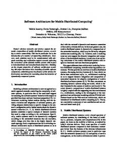
information was obtained fusing different sensors. In particular, for the case shown in this paper, the sensors used were a force/torque sensor, an accelerometer and the joint sensors. The objective of this integration was to develop a force observer capable of estimating, accurately and from the f/t sensor measurements -which reflect the contact forces, the inertial ones and the gravity forces- , the contact force exerted by a manipulator to its environment (Gamez et al., 2008). To carry out this test, some of the components that were described before in the previous section were used.
Fig. 8. Force measurement from the wrist sensor ATI (upper-left), force observer output (upper-right), accelerometer output (lower-left) and real and measured position of the robot tip for y-axis (lower-right). The results obtained applying the force/position controller, where the information of the force observer is used, are presented in Fig. 8. The experiment consisted of a movement in the axis z of three phases: an initial movement in free space (from t =5s to t = 6.2s), a contact transition (from t =6.2s to t = 6.4s) and a movement in constrained space (from t =6.4s to t = 9s). Apart from the force compensation shown in Fig. 8, it can be also compared how the observer eliminates the inertial effects and the noise introduced by the sensors. Note the time lag between the filtered signal and the original one. It was because the selection of the gains made the poles of observer to be quite near the unit-circle (Gamez, 2006). The force control loop applied was an impedance controller (Hogan, 1985).
Open Software Architecture for Advanced Control of Robotic Manipulators
393
6. Discussion The construction of the open robotic system developed in the framework of this work was necessary because, as it is well known, industrial manipulators do not offer, with an appropriate bandwidth, the possibility of integrating either advanced control algorithms or new sensors into the software-hardware architecture. This fact forced the research community to extend an industrial manipulator architecture in order to get a completely open one in both senses: hardware and software. The proposed platform was designed considering a multi-layer structure that simplified the integration of external functionality in several ways. The first one consisted of offering different interfaces where the user was capable of reading all the parameters and variables, besides modifying the commanded signals, with a considerable bandwidth. The second one pretended to avoid the limitation of the industrial robots where the current methodology is to control exclusively the position without considering high level strategies for task decision making, or without taking into account new sensors that could improve the environment modelling. Certainly, a pending aspect of this platform is the the man-machine interaction. New solutions in the area of software technology have to be included in order to create a more friendly-interface that permits to modify easily the requirements of the system, especially for the experiment generation. Perhaps, creating pseudo intelligent task interpreters, as a experimental interface, will play an important role. Furthermore, it has to be pointed out that the design solutions have been driven following a trade-off between mass products (paying attention to the cost) and standardization requirements (leading edge technology). On the other hand, the proposed architecture was based on consolidated open robotic platforms, specially on those ones developed in Lund University (Sweden) and Leuven University (Belgium). These platforms have been developed during several decades and have accumulated a great deal of experience, representing an excellent paradigm for initial developments. In addition, a narrow collaboration with the company of the manipulator robot has existed, what allowed access to internal functions and hardware what would be impossible in other conditions. To conclude this section, the development of this kind of platforms does not only prove to be useful for testing advance control algorithms, but also it is necessary to emphasize the necessity of building such systems since, from a robotic research point of view, and mainly, from a robotic manufacturers overview, it helps to increase the development speed opening up the systems for third party.
7. Conclusions This work describes an experimental platform that allows the implementation of modelbased and sensor-based control algorithms in robotic manipulator. Particulary, this new system allows to easily integrate new sensors and advance control algorithms in an Stäubli industrial 6-dof robot using a component-based software methodology. Based on a component-based development approach, two possible configurations were described, explaining why the original structure was modified migrating to a new one where the Master PC was different to the controller PC. It is also explained how the fact of using this paradigm allowed an easy reconfiguration of the robotic platform, demonstrating
394
Advanced Strategies for Robot Manipulators
that the use of components -i. e. Sensor components- , that are independent of the context, allowed as well an important restructuration of the new robotic architecture. The resulting architecture has been designed, among other objectives, to allow different sensors to be easily switched and rewired depending on the new sensor fusion or control strategy that must be tested. Together with the component-based development approach, a software structure of layers has been proposed to facilitate the design, configuration and testing of new control algorithms and sensor fusion techniques. This structure allows systems of components, with standardized interfaces, to be connected while abstracting away implementation details of components. Eventually, a number of experiments were performed to validate the performance of the proposed architecture and its capacity of allowing a fast and easy implementation of advance control algorithms in non-structured environments.
8. References Ahn, S. C., Lee, J.-W., Lim, K.-W., Ko, H., Kwon, Y.-M. & Kim, H.-G. (2006). Requirements to UPnP for Robot Middleware, Proc. of the 2006 IEEE/RSJ Int. Conf. on Intelligent Robots and Systems (IROS), Beijing, pp. 4716 -4721. Ando, N., Suehiro, T., Kitagaki, K. & Kotoku, T. (2006). RT (Robot Technology)-Component and its Standarization, SICE-ICASE International Joint Conference, 2006, pp. 26332638. Bruyninckx, H. (2001). Open robot control software: the OROCOS project. Proc. of the 2001 IEEE Int. Conf. on Robotics and Automation (ICRA), pp. 2523–2528. Chishiro, H., Fujita, Y., Takeda, A., Kojima, Y., Funaoka, K., Kato, S. & Yamasaki, N. (2009). Extended RT-Component Framework for RT-Middleware, IEEE International Symposium on Object/Component/Service-Oriented Real-Time Distributed Computing, 2009 (ISORC), pp. 161-168. Cote, C., Brosseau, Y., Letourneau, D., Raievsky, C. & Michaud, F. (2006). Robotic Software Integration Using MARIE, International Journal of Advanced Robotic Systems, 2006, pp. 055-060. Gamez, J., Robertsson, A., Gomez, J. & Johansson, R. (2004). Sensor fusion of force and acceleration for robot force control. Int. Conf. Intelligent Robots and Systems (IROS 2004), 2004, pp. 3009–3014. Gamez, J., Robertsson, A., Gomez, J. & Johansson, R. (2005). Force and acceleration sensor fusion for compliant robot motion control. IEEE Int. Conf. on Robotics and Automation (ICRA2005), 2005, pp. 2709 - 2714. Gamez, J. Sensor Fusion of Force. (2006). Acceleration and Position for Compliant Robot Motion Control. Phd thesis, Jaen University, Spain, 2006. Gamez, J., Gomez, J. Nieto, L. & Sanchez Garcia, A. (2007). Design and validation of an open architecture for an industrial robot control, IEEE International Symposium on Industrial Electronics (IEEE ISIE 2007), 2007, pp. 2004–2009. Gamez, J., Robertsson, A., Gomez, J. & Johansson, R. Sensor fusion for compliant robot motion control. IEEE Trans. on Robotics, 2008, pp. 430–441. Gamez, J., Gomez, J., Sanchez, A. & Satorres, S. (2009). Robotic software architecture for multisensor fusion system. IEEE Trans. on Industrial Electronics, 2009, pp. 766–777. Groover, M. P. (2008). Automation, Production Systems and Computer-Integrated Manufacturing. Pearson Education, Upper Saddle River, New Jersey, USA, 2008.
Open Software Architecture for Advanced Control of Robotic Manipulators
395
Hogan, N. (1985). Impedance control: An approach to manipulation, parts 1-3. J. of Dynamic Systems, Measurement and Control. ASME, 1985, pp. 1–24. Hong, K. Kim, J. Huh, C., Choi, K. & Lee, S. (2001). A pc-based open robot control system: PC-ORC. IEEE International Symposium on Industrial Electronics, ISIE 2001. 2001, pp. 1901 –1906. Johansson, R. & Robertsson, A. (2003). Robotic force control using observer-based strict positive real impedance control. IEEE Proc. Int. Conf. Robotics and Automation, 2003, pp. 3686–3691. Khatib, O. & Burdick, J. (1986). Motion and force control of robot manipulators. IEEE Int. Conf. Robotics and Automation, 1986, pp 1381– 1386. Kröger, T., Kubus, D. & Wahl, F. (2007). Force and acceleration sensor fusion for compliant manipulation control in 6 degrees of freedom. Advanced Robotics, 2007, pp. 1603– 1616. Larsson, U., Forsberg, J. & Wenersson, A. (1996). Mobile robot localization: integrating measurements from a time-of-flight laser. IEEE Trans. Industrial Electronics, 1996, pp. 422–431. Luo, R., Yih, C. & Su, K. (2002). Multisensor fusion and integration: approaches, applications, and future research directions. IEEE Sensors J.,2002, pp. 107–119. Nesnas, I., Wrigh, A., Bajracharya, M., Simmons, R. & Estlin, T. (2003). CLARAty and Challenges of Developing Interoperable Robotic Software, Proceedings of the 2003 IEEE/RSJ. Intl. Conference on Intelligent Robots and Systems, 2003, pp. 2428 – 2435. Nilsson, K. & Johansson, R. (1999). Integrated architecture for industrial robot programming and control. J. Robotics and Autonomous Systems, 1999, pp. 205–226. OMG Robotic Technology Component Specification, formal/08-04-04 edition. Object Management Group, 2008. ORCA, http://orca-robotic.sourceforge.net/, 2010. OROCOS-Simulik, http://www.orocos.org/simulink/, 2010. OSACA, Open System Architecture for Controls within Automation Systems, ESPRIT III Project 6379/9115, 1996. Ostrovrsnik, R., Hace, A. & Terbuc, M. (2003). Use of open source software for hard realtime experiments, IEEE International Conference on Industrial Technology, 2003, pp. 1243 – 1246. Park, H. & Han, S. (2009). Development of an Open Software Platform for Robotics Services, ICCAS-SICE Int. Joint Conference, 2009, pp. 4773 – 4775. Pertin, F. & Bonnet des Tuves, J. (2004). Real time robot controller abstraction layer. Proc. Int. Symposium on Robots (ISR), Paris, France, March 2004. Saravanan, K., Thangavelu, A. & Rameshbabu, K. (2009). A middleware architectural framework for vehicular safety over vanet (InVANET). International Conference on Networks & Communications, 2009, pp. 277 – 282. Sarker, M., Kim, C., Cho, J. & You, B. (2006). Development of a Network-based Real-Time Robot Control System over IEEE 1394: Using Open Source Software Platform, IEEE International Conference on Mechatronics, 2006, pp. 563 – 568. Schlegel, C. & Worz, R. (1999). The Software Framework {SMARTSOFT} for implementing Sensorimotor Systems, Proc. IEEE Int. Conf. Intelligent Robots and Systems, 1999, pp 1610-1616.
396
Advanced Strategies for Robot Manipulators
Utz, H., Sablatnög, S., Enderle, S. & Kraetzschmar, G. (2002). MIRO - Middleware for mobile robot applications, IEEE Transactions on Robotics and Automation, 2002, pp. 493 – 497. Wills, L., Kannan, S., Sander, S., Guler, M., Heck, B., Prasad, J., Schrage, D. & Vachtsevanos, G. (2001). An Open Platform for Reconfigurable Control, IEEE Control Systems Magazine, 2001, pp. 49 – 64. Wind-River. VxWorks: Reference Manual. Wind River Systems, 2005. Wind-River Linux. http://www.windriver.com/products/linux/, 2010. Xenomai: Real-Time Framework for Linux. http://www.xenomai.org/, 2010. Xu, H. & Jia, P. (2006). RTOC: A RT-Linux Based Open Robot Controller, IEEE/RSJ International Conference on Intelligent Robots and Systems, 2006, pp. 1644 – 1649. Xuemei, L. & Liangzhong, J. (2007). Study on control system architecture of modular robot. Proc. of the 2007 IEEE Int. Conf. on Robotics and Biometrics, 2007, pp. 508 – 512.