software is based on NuttX real-time operating system (RTOS). For communication ... from ClearPath, costs around 30,000 u$s in the basic A200 model. It is very ...
2017 Eight Argentine Symposium and Conference on Embedded Systems (CASE) ISBN: 978-987-46297-1-5 E-Book: 978-987-46297-2-2 Printed IEEE CATALOG: CFP1746V-PRT IEEE XPLORE: CFP1746V-ART
Open-source embedded framework for Unmanned Ground Vehicle control using CIAA Facundo Pessacg∗ , Mat´ıas Nitsche∗ , Adri´an Teijeiro‡ , Diego Mart´ın‡ and Pablo De Crist´oforis∗† ∗ CONICET-Universidad † Universidad
de Buenos Aires, Instituto de Investigaci´on en Ciencias de la Computaci´on (ICC) de Buenos Aires, Facultad de Ciencias Exactas y Naturales, Departamento de Computaci´on ‡ Facultad de Arquitectura, Dise˜ no y Urbanismo, Universidad de Buenos Aires
designed mainly for educational proposes and do not satisfy the research needs for field robotics. When considering new low-cost and and commercial off the shelf (COTS) based hardware prototypes, the Arduino [10] ecosystem is undeniably a widely used platform. Arduino is an open-source and open-hardware initiative started in 2003. Most Arduino board designs are based an Atmel 8-bit AVR micro-controllers and, more recently, on 32-bit ARM microcontrollers. Moreover, due to its open nature, third-party new micro-controller development boards can be easily integrated to the Arduino framework. One particularly popular robotic control framework corresponds the ArduPilot project [11]. This framework targets ground, aerial, terrestrial and even underwater robots. While initially based on the Arduino framework and on AVR microcontrollers (using the ArduPilotMega board), the project now targets modern ARM-based micro-controller boards (also known as autopilot boards). Another widely used open robotics framework is the Pixhawk [12] project. With similar goals to that of ArduPilot project, this project is more research-oriented, being started in 2009 by the Computer Vision and Geometry Lab at ETH, Zurich. Nowadays, the Pixhawk project supports many different autopilot boards. While ease of use by non-experts has allowed Arduino to be used as the basis of robotic platforms, for efficient real-time operation of larger complex systems other embedded software frameworks can be considered. In fact, the ArduPilot project is now based on the same base software as Pixhawk uses, and thus can run on the same series of autopilot boards. Instead of Arduino, the Pixhawk project is based on the NuttX [13] RTOS (Real-Time Operating System), which offers a rich hardware abstraction layer and real-time programming resources such as threads and tasks. In terms of control of ground mobile-robots, these frameworks present limitations. First, while an ArduRover variant exists, it mainly targets remote-control style cars with Ackerman steering. Moreover, there is no support for tight closedloop control of each actuator (based on incremental encoders, for example). Second, these projects are large and development cycles are short enough to difficult developing stable versions of the framework upon which to base any new extensions. One particularly interesting open-source and open-hardware system is the CIAA (Computadora Industrial Abierta Ar-
Abstract—In this paper a new open-source and open-hardware framework for Unmanned Ground Vehicle (UGV) control is described. The hardware is based on CIAA (Computadora Industrial Abierta Argentina) and Arduino modules while the software is based on NuttX real-time operating system (RTOS). For communication, the MAVlink protocol is used, also enabling interfacing with ROS (Robot Operating System). The framework can be employed for different style UGVs (differential drive, omnidirectional, skid steer) with different number of motorized wheels. It is designed for low-cost and ease of integration and adoption. The proposed framework was employed as the control system of a four-wheel skid-steer rover protoype developed by the authors, which is also described as a part of this work.
I. I NTRODUCTION Mobile robotics has become one of the most interesting areas in the field of robotics. The development of new ground robot prototypes has made significant progress in recent decades, which has allowed their use in different environments, for a variety of purposes. For example, in factories [1], [2], [3], precision agriculture [4], [5] or space exploration [6]. In order to develop all these applications it is first necessary to have robotic research platforms where new algorithms and methods can be tested. Nowadays, there are many commercially available ground mobile robots designed to meet research needs in robotics labs. Research-oriented robot platforms are generally designed for ease of integration to existing systems and mounting different kinds of sensors and processing units. Most commercial mobile robots have their own control system that are designed exclusively for the application which they are marketed for and its locomotion type (differential, skid steer, omnidirectional) [7] and number of actuators. These proprietary systems are closed technology and therefore make modifications or maintenance of the system to a large extent difficult. Besides these disadvantages, the other main drawback of commercial systems is their cost. For instance, the wellknown research-oriented mobile robotic base called Husky [8] from ClearPath, costs around 30,000 u$s in the basic A200 model. It is very difficult for universities or research labs from developing countries to afford these costs and hence this severely limits the possibilities of buying or upgrading these platforms to carry out field robotics research. On the other hand, low-cost open hardware platforms can be found, such as TurtleBot [9]. However, these robots are
35
2017 Eight Argentine Symposium and Conference on Embedded Systems (CASE) ISBN: 978-987-46297-1-5 E-Book: 978-987-46297-2-2 Printed IEEE CATALOG: CFP1746V-PRT IEEE XPLORE: CFP1746V-ART
gentina) [14].The CIAA is presented as the world’s first and only open industrial computer. On one hand, it is designed for the exigencies of industrial applications On the other hand it is open, since all information about its hardware design, firmware, software, etc. is freely available under the permissive BSD License. The CIAA computer presents itself as an interesting platform to implement the proposed framework and is thus used in this work for this purpose. In this paper a new open-source control system for wheeled robots is described. The chosen hardware for the system are CIAA (Computadora Industrial Abierta Argentina) and Arduino modules while the software runs on NuttX real-time operating system (RTOS). For external communication the MAVLink protocol was used which allows the system to be controlled by ROS (Robot Operating System). To tackle the diversity of possible robot locomotion types, the presented framework is scalable to different motor and wheel configurations, both in terms of the software and the hardware.
III. H ARDWARE D ESCRIPTION While not really tied to a specific hardware platform, the aim is to employ readily available COTS hardware. In this sense, we propose to use CIAA computer, an open-hardware initiative intended to be used in industrial environments. The CIAA in this case is used as the Robot Controller module. On the other hand, since one of the design considerations for the proposed framework is to support robots with varying number of motors, the MCM are to be implemented via independent micro-controllers. In order to reduce costs, small Arduino compatible boards were used. Specifically, Arduino Pro Mini boards were used for the current version of the system. The CIAA and the Arduino modules intercommunicate using the simple I2 C bus, which is scalable to a high number of devices and only requires two wires. In order to integrate the CIAA and Arduino boards in a single hardware system, three circuit boards were designed. First, a daugtherboard (also known as shield in the Arduino terminology and as poncho for the case of the CIAA) for the CIAA was designed which includes a series of connectors to the other modules in the system. Second, a circuit board was also designed for the Arduino modules to be connected together via the I2 C bus to the CIAA. A third circuit board was designed which consists of a control panel for the robot. These hardware units are described below.
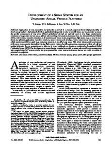
II. S YSTEM OVERVIEW The proposed system called OpenRover is comprised of a series of interconnected modules (see Figure 1). The Robot Controller Module (RCM) is the main component of the system and is in charge of controlling all of the robot subsystems, either directly or indirectly via the Motor Controllers Module (MCM). Each MCM is in charge of controlling an individual motor and is connected to the Robot Controller (via I2 C bus). The system is thus designed to support an arbitrary number of motors and locomotion types. The Robot Controller can also optionally employ low-level sensors such as sonar rangefinders for collision avoidance or an Intertial Measurement Unit (IMU).
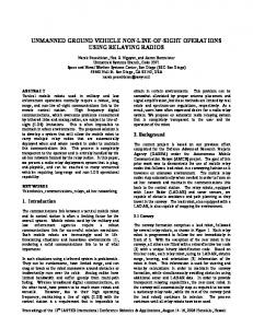
A. Motor Controllers The main goal of these modules is to perform closed-loop control of motor angular velocity. For this purpose, each Motor Controller is comprised of: an Arduino Pro Mini module, an incremental quadrature encoder, the motor driver and the motor itself (see Figure 2).
Companion Computer User Interface Extra Sensors
Robot Controller I 2C
Motor Controller
Motor Controller
Fig. 2. Motor Controller module description
Using the incremental quadrature encoder attached to the motor axis, the Arduino module senses the angular velocity of the motor. Since the Arduino module does not feature a specific quadrature decoder logic, a simple interrupt-based routine is used. Based on a given velocity setpoint (sent by the Motor Controller via the I2 C bus) and using a PID (Proportional Integrative Derivative) controller, the Arduino module computes a given PWM duty to be sent to the motor driver. The driver then translates this PWM pulse to a higher voltage and high current signal in order to move the motor at a given speed. The MTM is in charge of also maintaining the angular position of the wheel (knowing the gear reduction ratio and wheel diameter) for the purpose of robot odometry estimation,
Fig. 1. Module description of the OpenRover software-hardware framework.
For the purpose of control of the robotic platform via an external companion computer (such as an embedded SBC or laptop computer), the Robot Controller offers a communication interface using the MAVlink protocol. Given that MAVlink-ROS communication bridges already exist, this also enables ROS-based control of the robot. Communication can be established using different types of serial protocol adapters, via a wired interface or wirelessly using Bluetooth or WiFi. Finally, as part of the framework’s User Interface, the proposed system includes a control panel where the robot is to be turned on/off and where auxiliary information can be displayed (e.g. battery charge level).
36
2017 Eight Argentine Symposium and Conference on Embedded Systems (CASE) ISBN: 978-987-46297-1-5 E-Book: 978-987-46297-2-2 Printed IEEE CATALOG: CFP1746V-PRT IEEE XPLORE: CFP1746V-ART
typically used as input to more complex robot localization methods. Finally, the MCM also senses the current applied by the motor driver in order to estimate battery consumption by this motor and also to detect stall conditions, which should trigger an emergency halt of the remaining motors. A top-view of the designed MCM daughter-board (for the case of four-motors) is presented in Figure 3.
Fig. 4. CIAA shield: top-view of the board which connects to the CIAA male header pins on the underneath. On the top part, there are connectors to the MCM board (CONN MOT), for power input from batteries (PWR BATT), for communication (via USB-RS232 converter or Bluetooth adapter), for the optional sonar board and for the control panel (MAIN CONN). Fig. 3. Motor Controller Module circuit-board: in this case four-motors are supported, each with a connector leading to the corresponding driver (DRVn), quadrature encoder (ENCn) and I2 C bus (I2Cn). It also regulates input power to the rest of the system and includes a logic-level converter to translate 5V (used by Arduino modules) to 3.3V levels (used by CIAA)
can be interrupted by the user by pressing the emergency stop button of the control panel (see Section III-D). Another feature of the shield is the possibility of connecting an Inertial Measurement Unit (IMU) to the same I2 C bus. This sensor gives a better robot motion estimation and could be integrated by means of sensor fusion or simply by reporting raw values to the external computer for further processing. The current version of the shield is designed based on the pinout of the MPU6050 IMU. For the purpose of communication to an external computer (either embedded in the robot, externally mounted Laptop, an Android device, etc.) this shield exposes a serial connection which can be accessed in different ways. First, it is possible to connect via wire by means of an USB-RS232 adapter. Another possibility is to communicate wirelessly via Bluetooth using a HC-06 or similar adapter. Another option not included in current version is to also support WiFi communication using the low-cost ESP8266 module. In addition to the aforementioned communication port, the CIAA debug connection is also exported for flashing and debugging the CIAA board and to provide access to the interactive NuttX serial console. Another connector present in the shield is used monitoring the battery voltage by means of a resistor divider connecting to an ADC capable pin of the CIAA. For the purpose of controlling and monitoring the robot via an external panel, a connector is also included which exposes: motor enable signal, input power line, an I2 C connection for a graphic display and several connections for push buttons (for interaction via display). Finally, a connector which allows for the CIAA to control a sonar range-finder array is also included. This feature is conceived for obstacle avoidance or basic mapping of vehicle surroundings. The connector is designed to support up to
B. CIAA The CIAA board is currently available mainly in two forms: an industrial-oriented version and an educational version. The main difference between these is that the educational version does not feature many of the external components geared toward handling high current or high voltage external devices. For this reason, the industrial version does not have as many available I/O pins as the educational version. Thus, for the proposed framework we chose to use the latter. The CIAA includes an ARM Cortex-M4 LPC4337 microcontroller with ARM Cortex-M0 co-processor. The microcontroller has 1 MB of flash memory, 136 kB SRAM and 16 kB EEPROM. It operates at a clock frequency of more than 204 MHz. C. CIAA shiled A new shield or poncho for the CIAA was developed, which connects directly to the male I/O pins of the CIAA and exposes a series of connectors needed to communicate with the different hardware modules that comprise the system (see Figure 4 for designed circuit-board). In the first place, this shield has one connector for I2 C communication with the MCM, sending desired velocity commands and receiving the rotational displacement information of each motor for robot odometry computation. This connector also carries the motor enable signal, which turns on or off all motor drivers, which is directly controlled by the CIAA. This feature is necessary in case the CIAA needs to stop the motors immediately, for example if internal faults are detected in some of the hardware modules. This same enable signal
37
2017 Eight Argentine Symposium and Conference on Embedded Systems (CASE) ISBN: 978-987-46297-1-5 E-Book: 978-987-46297-2-2 Printed IEEE CATALOG: CFP1746V-PRT IEEE XPLORE: CFP1746V-ART
sixteen sonars by means of a an external demultiplexer which should be present in the sonar-array control board.
date this support is not yet complete. Moreover, it involves CIAA-specific interfaces which were undesirable given the previously stated driving goals for this framework.
D. Control Panel
A. Arduino Firmware
The final hardware component of the proposed framework is an external panel which permits control of basic aspects of the robot (Figure 5). First, this panel exposes a power onoff switch and a power indication LED. Second, it features an emergency-stop push-button which interrupts the motor enable line and also signals the CIAA about the emergency condition. The panel also features two USB connectors: one for wired communication with an external computer (when not using the Bluetooth wireless module on the CIAA shield) and another one connected to the CIAA debug port. A piezo-buzzer is included for encoding certain events (boot OK, boot failure, etc.) via specific sequence of tones. A graphical display is also included to inform of the robot state.
The firmware of the Arduino modules is in charge of controlling each motor of the robot. For this purpose, the Arduino modules are connected via two interrupt-capable I/O pins to the incremental quadrature encoder attached to the motor’s axis and to the motor driver via two PWM capable pins. For decoding the quadrature encoder signals, the Arduino Encoder library was used, which computes the incremental rotation of the encoder after each edge of either channel A or B signals using 16-bit resolution. For controlling motor velocity, two PWM signals are used. The Atmega328p microcontroller has one 16-bit resolution timer for finer control. Moreover, default PWM frequency is around 1 kHz which is low enough for motor commutation to be audible. For these reasons, the TimerOne library is used which exposes the 16-bit timer changing the PWM frequency to 20 kHz. Using the sensed incremental rotation of the motor shaft and given a certain angular velocity setpoint, closed-loop control of the motor is achieved via a simple PID controller. For this end, the PID Arduino library is used. In order to sense the correct operation of motors, the current-sense outputs of the motor driver are connected to ADC capable pins of the Arduino module. The motor drivers used in current version (IBT-2, featuring a BTS7960 IC) also inform of any overcurrent or overtemperature condition via a fixed current on this pin. Finally, for communication to the CIAA, an I2 C protocol was defined. This protocol is used for setting the velocity setpoint, reading the angular position of the wheel, setting PID constants, reading instantaneous and cumulative motor current and enabling or disabling the PID. The standard I2 C protocol lets the Main Controller (i.e. the CIAA) of the system to control each motor independently of the specific hardware. Thus, this design considers eventual upgrading of the MCM hardware.
Fig. 5. Control panel circuit-board: the main connector goes to the CIAA “poncho”, the USB connector goes to external panel-mounted USB ports. Other connectors expose the logic-power line to turn on/off robot control, the motor-enable line for emergency stop button and the graphical display.
IV. S OFTWARE D ESCRIPTION In addition to the development of the hardware components of the framework, the embedded software (or firmware) of the CIAA and Arduino modules is here described. In general terms, the driving goals for the embedded software development are to be: a) easily maintainable, b) based on common standards and c) not directly tied to a specific hardware platform. For the case of the Arduino modules, the Arduino libraries and IDE were used for rapid prototyping and simple software development of the corresponding firmware. While not as efficient as ad-hoc code, they were chosen for simple understanding and maintenance of the system. Moreover, Arduino nowadays is a standard among hobbyist and educational environments. For the case of the CIAA, since this board will be in control of many different tasks with real-time constraints, the use of an embedded Real-Time Operating System was decided. For this reason, the NuttX RTOS was chosen. While there are many freely available RTOS, NuttX has a series of features which stand-out among similar projects. Also, while the CIAA project includes a proposed firmware and RTOS, at present
B. CIAA Firmware The firmware for the CIAA is based on the NuttX RTOS. It has been widely used in other projects of development of robots control systems, both terrestrial and aerial. This has a strong impact in considering future CIAA project hardware developments and would even allow the use of other existing hardware platforms. NuttX mostly follows the architecture of the GNU/Linux OS, with a similar configuration utility and including the concept of architecture and device drivers, thus offering a standardized interface. In order to integrate the CIAA to NuttX, support for the onboard LPC4337 micro-controller was first added. A second support layer was defined to integrate the particular CIAA board. This requires assigning specific functions for each pin
38
2017 Eight Argentine Symposium and Conference on Embedded Systems (CASE) ISBN: 978-987-46297-1-5 E-Book: 978-987-46297-2-2 Printed IEEE CATALOG: CFP1746V-PRT IEEE XPLORE: CFP1746V-ART
(a) Motor Controllers, drivers and power stage
(b) CIAA ”poncho”
(c) Motors with encoders
Fig. 6. Proposed system hardware prototypes in ElementAll robot
(a) Basic
(b) With manipulator
the state of the stop button and resets the velocity setpoint of all motors to zero in order to avoid a jump when the emergency button is depressed. Finally, there is a watchdog which also disables the motors in case of communication timeout. Another task is to compute the forward kinematic model of the robot (differential, omnidirectional, etc.) in order to translate desired linear and angular robot velocity to angular wheel velocity. Similarly, the inverse kinematic model is also computed in order to estimate the robot motion from wheel rotation obtained from incremental encoders. The equations to compute the forward and inverse kinematic models for different locomotion configurations can be found in [15].
(c) Full sensors
Fig. 7. Different configurations for ElementAll rover: (a) basic configuration with only on-board sonar array, (b) with 6DoF manipulator, (c) with stereo-camareas, LIDAR and RTK-GPS. In all cases with two set of wheels in parallel for greater traction.
V. S YSTEM IMPLEMENTATION FOR THE E LEMENTA LL UGV PROTOTYPE
according to its use and writing specific drivers for custom components, such as the I2 C based MCM or external sonar control board. Finally, in the application layer of the RTOS, a user-level rover_control process is defined which holds most of the project-specific logic as a series of different tasks: 1) Communication: The first task is to monitor the serial communication line in order to receive external commands (e.g. desired robot linear and angular velocities) and inform about the robot state (e.g. odometry estimation). For communication, the MAVlink protocol is used, which is supported by a large number of GCS (Ground Control Software) used to monitor and control unmanned vehicles (typically aerial). Moreover, there is a mavros MAVlink to ROS bridge which translates messages from one system to the other. In this way, by supporting the MAVlink protocol, it is possible to interact with the proposed framework using standard ROS interfaces. 2) Battery Monitoring: A battery monitoring thread is started by the main task and measures the voltage via one of the on-board ADC ports. Two thresholds are defined which trigger different tones of the buzzer for early alert of lowbattery and critical charge-level to the user. 3) Motor Control Module: One of the main tasks performed by the CIAA is to control the vehicle’s motors via the MCMs. When the CIAA boots, communication via I2 C is attempted in order to identify all MCMs in the bus. Only after this identification step is successful, the motor enable line is activated in order to enable the motor drivers. Since the user can halt the motors by pressing the emergency stop button (which opens the enable line circuit), the CIAA also monitors
The framework presented in this work was implemented as part of the hardware/software system of a UGV protoype, the ElementAll robot (see Figures 7 and 6). This integration experience served the purpose of attesting the system design in terms of adaptation to a robotic research platform. In the following sections the ElementAll rover is first described and then integration considerations are discussed. A. Rover Description The ElementAll protoype is a skid-steer rover with four independently driven wheels. It was designed to operate in challenging terrain and weather conditions, such as high temperatures or under the rain or snow. It is conceived to be a research incremental platform, therefore the chassis is designed to allow different configurations and many sensors to be mounted on it. The basic model is only equipped with a sonar ring, however cameras, lasers range finders, IMUs and GPS are considered to may be added for specific perception purposes enhancing its autonomous navigation capabilities (see Figure 7). The ElementAll is driven by four 100W 12V brushed DC motors from REMSSI, with a maximum speed of 2000 rpm, and 0.45 Nm torque. Motors have corresponding STM gearbox with a 1:50 reduction ratio. This gives an approximate global torque of 50 Nm (considering gearbox efficiency). The tires are 4 ply rated, 4.80/4.0-8 size with aluminum rims. Wheels have an outer diameter of 0.39 m and are 0.09 m wide. The on-board energy source consists of two to eight 12V 9Ah lead-acid batteries connected in parallel. Motor drivers
39
2017 Eight Argentine Symposium and Conference on Embedded Systems (CASE) ISBN: 978-987-46297-1-5 E-Book: 978-987-46297-2-2 Printed IEEE CATALOG: CFP1746V-PRT IEEE XPLORE: CFP1746V-ART
are IBT-02, which are based on two BTS7960 half H-Bridge ICs. The maximum continuous current for this driver is 43A and features integrated over-current and over-temperature protection. As added protection, a breaker switch is included in the main power circuit.
VI. C ONCLUSION In this work, a new open-source framekwork for Unmanned Ground Vehicles is presented, supporting different types of robot locomotion and different motor number and configurations. The system hardware is based on CIAA (Computadora Industrial Abierta Argentina) and Arduino microcontrollers while the software is based on NuttX real-time operating system (RTOS). For external communication the MAVLink protocol was used which allows the system to be controlled by ROS (Robot Operating System). The proposed system presented in this work was integrated into the ElementAll prototype UGV. This integration experience allowed to verify the correctness and suitability of the chosen system design.
B. System Integration During the construction of the ElementAll prototype, the proposed framework was integrated as part of its control and communication sytem. Particular aspects of this integration stage are described here. 1) Motor Controllers integration: Since the ElementAll robot features a standard set of motor drivers featuring PWM control, current-sense and enable lines, the proposed Motor Controllers required no adaptation for interfacing. On the other hand, integration with motor incremental encoders required determining the apropriate encoder resolution. Since Arduino Pro Mini boards were used and since quadrature decoder logic is based on interrupt processing, encoder resolution was limited to 512 ticks per revolution. Using 4x counting, effective angular resolution is around 0.17 degress/tick. For the ElementAll prototype the capacitive encoders AMT10X from CUI Inc. were chosen. A switching regulator with a wide range of input voltage from 3V to 40V is used for the powersupply (present in the Motor Controllers board), which allows for using different battery technologies seamlessly. In Fig 6(a) a prototype for the Motor Controllers board installed inside the lower part of the ElementAll cabinet is presented. In Fig 6(c), the internal disposition of motors inside the metal frame can be seen, with encoders attach on the back of the motor axes. 2) Robot Controller integration: For the Robot Controller component, the CIAA “poncho” presented in previous sections was prototyped (Fig 6(b)) and integrated to the ElementAll cabinet and connected to the rest of the electronic components. After installation of the corresponding hardware, ElementAll specific parameters were defined for use in the Robot Controller: motor number, disposition and orientation, wheel diameter, encoder ticks per revolution and gearbox reduction ratio. Moreover, PID constants also needed to be determined. In order to tune these control loops, individual motor velocities were monitored via MAVlink protocol for different values of P, I and D constants. After observing correct response, these were permanently set. Another required step was to tune ADC conversion parameters for precise battery voltage level monitoring. After setting the low and critical thresholds for battery monitoring, correct operation of the alarms was checked. After completing required integration and configuration steps, rover communication with external computers was tested. For this purpose, the serial-Bluetooth adapter was used and both a Desktop computer with ROS installed and an Android Smartphone with the MAVlink compatible QGroundControl application were tested. Via this communication interface it was possible to monitor internal robot parameters as well as control the robot via high-level velocity commands.
VII. F UTURE W ORK As a future work we propose to finish the design, construction and integration of the sonar control-board with the proposed system. Moreover, we intend to produce final printed-circuit boards for all four hardware components. Also, we plan to release all relevant source-code, circuit schematics and circuit-board files in public repositories for adoption of the system in other platforms. Finally, we would also like to integrate the proposed framework in other similar robots to evaluate the scalability of the system. ACKNOWLEDGMENT The research was supported by PICT 2015-3167 of the Argentinian Ministry of Science and Technology and UBACyT 20020130300035BA of the University of Buenos Aires. R EFERENCES [1] S. Berman, E. Schechtman, and Y. Edan, “Evaluation of automatic guided vehicle systems,” Robotics and Computer-Integrated Manufacturing, vol. 25, no. 3, pp. 522–528, 2009. [2] H. Martinez-Barbera and D. Herrero-Perez, “Development of a flexible agv for flexible manufacturing systems,” Industrial Robot: An International Journal, vol. 37, no. 5, pp. 459–468, 2010. [3] H. Mart´ınez-Barber´a and D. Herrero-P´erez, “Autonomous navigation of an automated guided vehicle in industrial environments,” Robotics and Computer-Integrated Manufacturing, vol. 26, no. 4, pp. 296–311, 2010. [4] D. Bochtis, S. Vougioukas, H. Griepentrog et al., “A mission planner for an autonomous tractor,” Transactions of the ASABE, vol. 52, no. 5, pp. 1429–1440, 2009. [5] D. Johnson, D. Naffin, J. Puhalla, J. Sanchez, and C. Wellington, “Development and implementation of a team of robotic tractors for autonomous peat moss harvesting,” Journal of Field Robotics, vol. 26, no. 6-7, pp. 549–571, 2009. [6] R. Kerr, “Hang on! curiosity is plunging onto mars,” Science, vol. 336, no. 6088, pp. 1498–1499, 2012. [7] J. Borenstein, H. Everett, L. Feng et al., Where am I? Sensors and methods for mobile robot positioning, 1996, vol. 119, no. 120. [8] Husky. [Online]. Available: https://www.clearpathrobotics.com/huskyunmanned-ground-vehicle-robot/ [9] (2017) Turtlebot. [Online]. Available: http://www.turtlebot.com/ [10] Arduino. [Online]. Available: https://www.arduino.cc/ [11] APM. (2014) Ardupilot. [Online]. Available: http://www.ardupilot.org [12] L. Meier, D. Honegger, and M. Pollefeys, “PX4: A node-based multithreaded open source robotics framework for deeply embedded platforms,” 2015 IEEE ICRA, pp. 6235–6240, 2015. [13] G. Nutt. (2014) Nuttx. website. [Online]. Available: http://www.nuttx.org [14] Computadora Industrial Abierta Argentina (CIAA). [Online]. Available: http://www.proyecto-ciaa.com.ar [15] R. Siegwart, I. R. Nourbakhsh, and D. Scaramuzza, Introduction to autonomous mobile robots. MIT press, 2011.
40