of the GPP architecture, our solution only requires the code to be recompiled ..... architectures like ARM, the modulo division could be time consuming with ...
RADIOENGINEERING, VOL. 26, NO. 4, DECEMBER 2017
1083
Open-source Implementation of an Ad-hoc IEEE 802.11 a/g/p Software-defined Radio on Low-power and Low-cost General Purpose Processors Simone CICCIA 1, 2 , Giorgio GIORDANENGO 2 , Giuseppe VECCHI 1 1
Dept. of Electronics and Telecommunication (DET), Politecnico di Torino, Corso Duca degli Abruzzi, 24, 10029, Torino, Italy 2 Istituto Superiore Mario Boella, Via Pier Carlo Boggio, 61, 10138, Torino, Italy {simone.ciccia, giuseppe.vecchi}@polito.it, {ciccia, giordanengo}@ismb.it Submitted June 21, 2017 / Accepted October 20, 2017
Abstract. This work proposes a low-cost and low-power software-defined radio open-source platform with IEEE 802.11 a/g/p wireless communication capability. A stateof-the-art version of the IEEE 802.11 a/g/p software for GNU Radio (a free and open-source software development framework) is available online, but we show here that its computational complexity prevents operations in low-power general purpose processors, even at throughputs below the standard. We therefore propose an evolution of this software that achieves a faster and lighter IEEE 802.11 a/g/p transmitter and receiver, suitable for low-power general purpose processors, for which GNU Radio provides very limited support; we discuss and describe the software radio processing structuring that is necessary to achieve the goal, providing a review of signal processing techniques. In particular, we emphasize the advanced reduced-instruction set (RISC) machine (ARM) study case, for which we also optimize some of the processing libraries. The presented software will remain open-source.
Keywords Software-defined radio (SDR), General Purpose Processor (GPP), low-power wireless communications, advanced RISC machine (ARM), open-source software
1. Introduction Software Defined Radio (SDR) plays a key role in present and future wireless communications; its advantage over hardware realization is in providing flexible, maintainable, and low-cost radio equipment [1]. Since software can be modified, cancelled and upgraded, SDR has become popular both in products and in research, like mainstream cognitive radio [2] as well in more selected applications like reconfigurable antennas [3], [4]; SDR is also an optimal approach for researchers and students to experiment with radio communication and signal processing concepts [5]. It is also well
DOI: 10.13164/re.2017.1083
accepted in military, satellite communication and Vehicular Ad Hoc Networks (VANET) primarily for safety, security and privacy issues which can be meet by means of the SDR flexibility [6], [7]. However, such flexibility comes at the expense of increased power consumption, that is the challenge to overcome today. This work targets the implementation of a low-power and low-cost IEEE 802.11 a/g/p SDR on General Purpose Platforms (GPP). Since GPP implementation is not the only option addressed by the scientific community we first briefly review the current state-of-the-art of general SDR implementation; we will next focus on the state-of-the-art for GPP SDR implementation.
1.1 State of the Art: General Implementation of SDR Existing platforms to implement SDR include Field Programmable Gate Array (FPGA), Digital Signal Processors (DSP), GPP and combinations of these to distribute the computational complexity of the software radio to the most appropriate resource. Low-power and low-cost FPGA platforms are usually employed to accelerate some performancecritical functions of a software radio [8]. However, a full stack IEEE 802.11 a/g/p SDR implementation requires a costly hardware along with a large consumption as reported by the open-source SDR implementation proposed in [9]. Another disadvanges of FPGA is that, at present, they can be only partially reconfigured at run-time [10]. Performance-critical SDR tasks are also well assessed on DSP platforms, which are architectures specialized for signal processing. Atomix, a framework able to convert C code into DSP is presented in [11]. This publication illustrates a partial implementation of the IEEE 802.11a transceiver, with a reported consumption of 7 W. On the contrary our implementation targets the full IEEE 802.11 a/g/p SDR (i.e. transmitter and receiver) on a low-power GPP. Furthermore, [11] does not account for the consumption of the Front-End (FE); the Universal
APPLICATIONS OF WIRELESS COMMUNICATIONS
1084
S. CICCIA, ET AL., OPEN-SOURCE IMPLEMENTATION OF AN AD-HOC IEEE 802.11 A/G/P SOFTWARE-DEFINED RADIO . . .
Software Radio Peripheral (USRP)2 series employed in the test has a consumption of about 14W, and a significant cost. Finally, [11] does not clarify when and if the framework (including the partial IEEE 802.11a implementation) will be released as a free and open-source. It is also not clear if this framework could be used with a specific DSP hardware only (i.e. TI6670). Therefore, this solution is interesting and promising, but at present it is still at too early a stage to be assessed as low-cost and/or low-power; in contrast, our proposed work provides a complete implementation of the system and its validation.
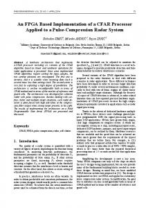
1.2 State of the Art: SDR Implementation on GPP GPPs are architectures designed to perform more general operation and they are commercially available at lowcost. This explains why they are so widespread. They are fully flexible and provide the advantages of dynamically controlling both hardware and software components of a radio. For example, a Linux shell script can schedule when the radio app and the FE should be active or off to further reduce energy consumption. However, the development of a low-power and lowcost full stack IEEE 802.11 a/g/p SDR is still challenging on GPP. First, this implementation requires a low-cost and low-power FE for direct baseband conversion over the desired frequency range. Commercial Digital Video BroadcastTerrestrial (DVB-T) hardware receivers, like Realtek-2832U chip [12], have been discovered to be programmable by the SDR community, and software to feed the In-phase and Quadrature components (I/Q) of the received signal into a host PC has been developed [13]. This device offers the cheapest way to play with SDR concepts, but its frequency coverage is limited to Ultra-High Frequency (UHF) band, therefore is useless for standards that rely on Industrial, Scientific and Medical (ISM) bands (e.g. 2.4 GHz and 5.8 GHz). Thus, a transceiver equipment like the HackRF FE is required to play with SDR at the mentioned bands [14]. Secondly, code performance is an issue. A straightforward software implementation of the IEEE 802.11 a/g/p standard, like the one offered by the GNU Radio community, can only run on desktop PC, due to its high computational power demand [15]. This limitation is immediately apparent when investigating the performance of the software into low-power boards; this is seen, e.g., in the snapshots reported in Fig. 1, that refer to the output of GNU Radio flowgraph. While the 802.11 standard would require a sampling rate of 20 MHz, when the available GNU Radio software is run at a sampling rate of 2 MHz, the integrated cores reach saturation and events like buffer underflow/overflow occur over the upcoming/incoming samples stream respectively. At this sampling rate (Fs,max = 2 MHz), the software receiver shows a high error rate of about 75 % that comes with overflows ("O" in the output display) and core saturations, which are inter-related, and most of the frames are corrupted and discarded. This happens because the processing
Fig. 1. Receiver performance at sampling rate Fs,max = 2 MHz, existing code on the targeted low-power board (see Sec. 2.2). The figure shows a snapshot of the GNU Radio flowgraph utility output for the existing IEEE 802.11 receiver, configured as described in Sec. 4.2. Top: Linux - htop program output;
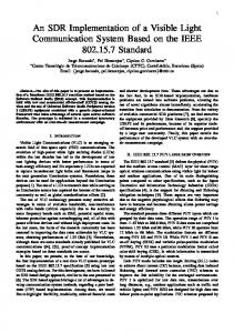
Fig. 2. Compiler output (make) building the work [16]. Issue preventing usability on platform different from X86 due to the lack of general implementation of part of the IEEE 802.11 software.
capability of the low-power board is insufficient for the existing state of the art GNU radio implementation. Even more evidently, perhaps, the board goes in protection state after a few minutes of operation. Some parts of this code have been recently optimized in [16]. The work in [16] was a source of inspiration to the present work; unfortunately, the code is not portable in architectures different from X86 (i.e. SSE2 instruction set) due to the lack of a generic implementation of a part of the software. This issue prevents installation on platforms different from X86, as reported in Fig. 2, thus requiring modifications to run on the targeted low-power platforms. Furthermore, although the code has optimized for real-time performance, [16] does not state or discuss the amount of throughput achieved with the proposed improvements. Among all possible framework for the development of SDR [17], we selected GNU Radio since it is free, open-source, comes with a wide availability
RADIOENGINEERING, VOL. 26, NO. 4, DECEMBER 2017
of signal processing libraries and a vast community [18]. To the best of our knowledge, the GNU Radio framework (as well as other SDR implementations) is fully optimized for the X86 processor architecture, where the compiler toolchain can fully exploit specific architectural features to improve efficiency. For instance, in [19] the authors describe a SDR code optimized for the X86 architecture, targeting multicore acceleration; but it is not released as an open-source. Conversely, Advanced Reduced instruction set computing Machine (ARM)-based processors still suffer from a lack of good compiler support, and from the lack of specific features available in X86 counterparts [20], [21]. In fact, no low-power implementations have been reported so far, especially on the new generation of low-cost, power-efficient ARM platforms [22]. It is also worth noting that GNU Radio framework officially supports only X86 processors, thus providing no guarantees for its porting on ARM (or other) processors. The open-source Sora project is, at present, a complete realtime SDR compliant with the IEEE 802.11 standard; however, this implementation requires a specific and costly hardware, and it needs to be employed on a PC [23]as opposed to the application targeted here. With the aim to provide low-cost and low-power SDR, the present work is intended to overcome the above limitations, and to yield SDR software requiring minimal hardware, i.e. a low-power and low-cost FE and GPP.
1.3 Proposed SDR Implementation on GPP In our intended application, there are no stringent requirements in terms of real-time performance; this allows to target low-power and low-cost GPP processor instead of DSP or FPGA implementations. As a result, our solution also maintains a significantly larger flexibility and code portability over other platforms. For example, in the case of a change of the GPP architecture, our solution only requires the code to be recompiled without the need for making changes in the source code. We start from a generic SDR implementation of the IEEE 802.11 a/g/p for desktop PC that at present is the only free and open-source software, and illustrate how to enhance code performance to achieve integration in low-power GPP while maintaining software portability, at minimal SDR cost.
1085
2. Hardware Issues We begin by discussing hardware issues, with specific attention to low power, and their impact and requirements on software development.
2.1 Front-End Issues This section provides an overview of possible FEs suitable for the SDR implementation of the IEEE 802.11 a/g/p in GNU Radio and discusses the related issues. To the best of our knowledge, valuable FE options for lowcost and low-power SDR which cover the IEEE 802.11 bands are summarized in the following with comments relevant to the present endeavor: • Hack RF (299$), supported by GNU Radio; Half-duplex operations only. • microSDR (expected 100$) according to [8]; at the time of this publication it is still under fabrication. • PicoZeD SDR 1x1 (750$) [25]; Supported by Matlab and Simulink, but not guaranteed for GNU Radio. • USRP-B series (more or less 800$ based on the model); supported by GNU Radio, Full-duplex operations. Other FEs as Lime SDR are not considered in this discussion since they do not provide coverage at 5.8 GHz [26], [27]. In view of the above, our analysis and tests have considered the only two viable solutions, i.e. Hack RF and USRP-B. In the following we will discuss tests and findings that have guided our final selection. A simplified circuit that shows analog and digital components of the receiver side is depicted in Fig. 3. The signal received in the bandwidth of interest is baseband transformed via a frequency down-conversion process. This analog elaboration produces a complex signal made up of I/Q components. Then Analog to Digital Converters (ADC)s map the analog values of the I/Q components to discrete levels. These converters have fixed sampling rate, thus a digital interpolation and decimation process is usually applied to get the sampling rate required by the intended communication standard. Finally, the digital I/Q sample stream is feed in the GPP for digital signal processing tasks. The same chain (reversed), applies to the transmission process.
To the best of our knowledge, there is no other implementations that provide SDR IEEE 802.11 a/g/p with the obtained performance on low-power and low-cost ARM-based boards. The code is available online at [24]. The paper is structured as follows. We start by reviewing requirements and available hardware for the FE (Sec. 2.1) and the GPP (Sec. 2.2); we then describe the realization of the SDR by describing the proposed method (Sec. 3) and we present the achieved results in Sec. 4. Section 5 collects the conclusions and perspectives.
Fig. 3. Schematic circuit description of a typical homodyne receiver.
S. CICCIA, ET AL., OPEN-SOURCE IMPLEMENTATION OF AN AD-HOC IEEE 802.11 A/G/P SOFTWARE-DEFINED RADIO . . .
1086
The first issue to address is the interface between the FE and the low-power GPP. In other worlds, the interface has to support the transfer rate RT in bps as described by the following equation: RT = (Ibits + Qbits )Fs,max
(1)
where Ibits and Qbits are the ADC bits dedicated to the Inphase and Quadrature component respectively, while Fs,max is the sampling rate (in Hz) required by the intended communication standard. The Hack RF uses the Universal Serial Bus (USB) v2.0 interface, which nominally supports 480 Mbps transfer rate; in this specific device the ADCs have 8 bits resolution for the I/Q components; inserting these values in (1), together with the IEEE 802.11 maximum sampling rate of Fs,max = 20 MHz, one obtains RT = 320 Mbps; thus, it appears to be fine for unidirectional (half-duplex) communication. Ettus Research USRP-B operates via USB v3.0, which nominally supports 5 Gbps transfer rate. This FE provides 12 bits ADCs for I/Q, that coupled to a sampling rate of Fs,max = 20 MHz (IEEE 802.11) gives a transfer rate of 560 Mbps, i.e. a large margin with respect the USB v3.0 limit [28].
Fig. 4. Data rate logger output of the Hack RF standard transfer test at 20 MHz rate (Half Duplex). Receiver test (Up) and transmitter test (Bottom).
However, as part of the selection process, we performed standard transfer tests on both these front-ends; we found the behaviors reported in the snapshots in Figs. 4 and 5, and summarized by the data in Tab. 1. It is apparent from these data that none is actually compliant with the IEEE 802.11 standard as both are unable to sustain the required sampling rate (i.e. 20 MHz). Hack RF is capable to transfer I/Q data into low-power GPP at such rate in standalone, while only in half-duplex mode. On the contrary, when associated to any IEEE 802.11 software the effective rate is very reduced, probably because the transceiver loses the execution priority with respect the tasks of the running software (i.e. availability of threads to perform its task on time). Conversely, USRP-B fails the transfer test at 20 MHz rate in full-duplex mode even in standalone. In view of the results in Tab. 1, we have selected USRP-B as front-end; it is apparent that (in a symmetrical link) there is no significant difference in throughput between half- and full-duplex; most of our results will refer to half-duplex operation for simplicity. Front-End USRP-B USRP-B USRP-B USRP-B HACK RF HACK RF
Samp.Rate[MHz] 8 0.5 17 1 20 0.5
Mode full-duplex full-duplex half-duplex half-duplex half-duplex half-duplex
Description Standalone connection Coupled with IEEE802.11 software Standalone connection Coupled with IEEE802.11 software Standalone connection Coupled with IEEE802.11 software
Tab. 1. The maximum sampling rate at which front-end devices passed the standard transfer tests on the low-power board in standalone, and coupled with existing IEEE 802.11 software.
Fig. 5. Data rate logger output of the USRP-B205 mini standard transfer test at 20 MHz rate (Full Duplex).
2.2 GPP Platform To satisfy the requirements of a more energy-efficient hardware, with low-cost property (74$) and small form factor, we targeted this project to the Odroid-XU4 [29]. This ARMbased board is made up by a selectable high performance quad-core Cortex-A15 and a lower-performance quad-core Cortex-A7 Cental Processing Unit (CPU)s. These processors include Neon-technology, an instruction set able to accelerate signal processing algorithm [30]. The drawback is that they come with a specific Linux distributions that in general does not perform fast enough for a SDR environment, e.g. slow USB buffer copies could prevent the interaction
RADIOENGINEERING, VOL. 26, NO. 4, DECEMBER 2017
with the FE. A kernel modification is then required to fully exploit the performance of such boards. The downgrade of the kernel is accomplished by recompiling with options full kernel-preemption, overclocking and Neon.
3. Operations, Algorithms and Optimizations The processing required by the IEEE 802.11 to code and decode its waveform involves a massive number of arithmetic operations. Therefore, in the following we will analyze the most relevant such computational tasks, with a specific emphasis on those that can be substantially improved; this will constitute the starting point of the optimization. In order to identify bottlenecks and heavy processing blocks of the IEEE 802.11 a/g/p flowgraph for GNU Radio we employed Control Port (CP) monitor performance, a tool recently added in GNU Radio by the work [31]. Figure 6 shows a simplified flowgraph description of the IEEE 802.11 a/g/p baseband processing showing with a lighter color the blocks we found critical according to CP, and that have been restructured by this work.
Fig. 6. Simplified GNU Radio flowgraph of the IEEE 802.11 a/g/p baseband processing chain.
1087
able memory that can be exploited for reducing the runtime complexity of signal processing tasks. This approach is also discussed in [23] but never addressed from the implementation point of view. Another significant enhancement in performance is obtained by operating on bytes instead of bits since the same operation is parallelized over 8 bits at the same time. Some examples of operations to which this optimization process is applied are: • Scrambler process • Convolutional encoder • Interleaving • CRC computation Significant improvements can also be reached by unrolling for–loops. This is the case of the OFDM Carrier Allocator. Its body was constituted by an initialization of a large output buffer onto which two sequential loops write information and pilot symbols, respectively. In our implementation of the OFDM Carrier Allocator the information, pilot symbols and guard intervals are allocated cyclically avoiding initialization and stressing loops. This effectively reduces the computational complexity on all architectures and, even more so, on ARM-based board since the compiler is not able to efficiently handle for-loops. The proposed implementation of the OFDM Carrier Allocator is reported in Appendix. Regarding the demapping-decision process, we have implemented the same suboptimal method that has recently added online by the work [16]. We found that this method gives a 70× boost in the code speedup with respect the optimal method proposed by the IT++ library. Several authors have investigated the performance of this approach, and the works in [33–35] have demonstrated a loss of only 2 dB in the Bit Error Rate (BER).
The following sub-sections will discuss the restructuring of such flowgraph in the order of the proposed optimization methods.
Finally, frequency offset compensation and equalization are not modified since the CP analyses has not revealed critical aspects in performance.
A first note is about Fast Fourier Transform (FFT) and its inverse; they are basic functions that GNU Radio provides; accelerations of these functions are already available [32], and thus will be not discussed here.
3.2 A Practical Example of Platform Generic Optimization
3.1 Platform Generic Optimization A ubiquitous source of inefficiency is the handling of shift register which are to perform a large number of operations. However, shift registers have a finite set of possible states and therefore their associated operation can be computed once at run-time and stored in Look Up Tables (LUT). This operation is beneficial in typical SDR platform since they are processor-based system with large amounts of avail-
To provide a concrete example, in the following we report a step-by-step demonstration to speedup the scrambling processing function, showing some tricks. The IEEE 802.11 a/g/p scrambler is defined by (2), which shows the polynomial representation p(x) = x 7 + x 4 + 1. (2) Its flow graph is reported in Fig. 7. The scrambler Shift Register (SR) starts with the all-ones state. The Pseudo-Random Binary Sequence (PRBS) is periodic and repeats after a period defined in the (3), which shows the number of possible states.
S. CICCIA, ET AL., OPEN-SOURCE IMPLEMENTATION OF AN AD-HOC IEEE 802.11 A/G/P SOFTWARE-DEFINED RADIO . . .
1088
PRBS_PE RIOD = 27 − 1.
(3)
STATE 0 1 2 3 4 5 6 7 8 9 10 11 12 .. 126
Fig. 7. Scrambler block diagram and illustration of the PseudoRandom Binary Sequence (PRBS) generator.
The scrambler provided by the IEEE 802.11 a/g/p for GNU Radio computes the PRBS state for each input data bit (i.e. unpacked bytes) as shown in the following code: 0
/** General work**/
1
for (int i = 0; i < n_data_bits ; i++)
2
{
3
PRBS = (!!( state & 64)) ^ (!!( state & 8));
4
out[i] = PRBS ^ in[i];
5
state = (( state 127) state = 1;
7
}
where the general work describes the part that reads inputs, processes, and writes outputs. This code offers poor performance since carry out many operations for each input bit. The complexity of signal processing can be reduced by exploiting memory availability. Since PRBS is periodic, it can be generated once in the constructor and stored in a LUT. In C/C++ programming language, the constructor is a section of code executed only once at run-time (i.e. when the object is created). We proposed the following restructuring of the PRBS: 0
/**Code constructor **/
1
SR = 0x7F;
2
for(int state = 0; state < PRBS_PERIOD ; state ++)
PRBS 0 0 0 0 1 1 1 0 1 1 1 1 0 . 1
PACKED_PRBS 11111110 11111100 11111000 11110000 11100001 11000011 10000111 00001110 00011101 00111011 01110111 11101111 11011110 ........ 11111111
Tab. 2. Look Up Tables (LUT)s for the Scrambler processing function.
packed in one byte. This operation requires a different LUT that stores eight successive states of the PRBS, as reported in Tab. 2. In this way, the new PRBS LUT is generated in the constructor as: 0
/**Code constructor **/
1
for(int state = 7; state < PRBS_PERIOD +7; state ++)
2
for(int j = 7; j >= 0; j--)
3
PACKED_PRBS [state % PRBS_PERIOD ] |= (PRBS [(( state - j) % PRBS_PERIOD )] & 0x01) > 3) & 0x01;
6
SR
7
SR |= PRBS[ state ] > 1;
This optimization yields the following general work:
0
/** General work**/
2
{
1
for(int i = 0; i < n_data_bytes ; i++)
3
out[i] = in[i] ^ PRBS[ state ];
2
4 5
state = ( state + 1) % PRBS_PERIOD ; }
{
3
packed_out [i] = packed_in [i] ^ PACKED_PRBS [state ];
4
state += 8; if( state > PRBS_PERIOD )
5
As a consequence, the number of operation reduces to a memory access and an XOR operation for each bit. Furthermore, a second step optimization is still possible by operating on bytes instead of bits. In this case eight information bits are
6 7
state -= PRBS_PERIOD ; }
In this way, the modulo division is removed.
RADIOENGINEERING, VOL. 26, NO. 4, DECEMBER 2017
3.3 Platform Specific Optimization High speed Single Instruction Multi Data (SIMD) functions are very efficient and allow parallel operations, and their use was proposed in work [16], [19], [23], [36]. They are usually employed for the most critical task requiring acceleration. However, this type of optimization is strictly related to the architecture employed, because it exploits registers and instruction sets intrinsic to the processor. The code written with this method is therefore not portable; because of this, we used it only for the most critical tasks (e.g. to accelerate the Viterbi decoder), and always also keeping (i.e. providing) a generic version suitable for all processors. At the receiver side, the synchronizer implements the maximum normalized correlation algorithm. This part involves many arithmetic operations at the signal sampling rate (i.e. before packet detector) and the use of accelerators is usually required. For this purpose we used the SIMD functions whose implementation and performance impact on ARM processors are well discussed in [36]. As these functions are architecture dependent, our proposed software provides also a platform-independent (generic) implementation to maintain the code portable. At the software building stage the compiler can choose the SIMD functions if supported on the target platform, otherwise select the generic-implementation counterpart. We found out that the Viterbi decoder was a significant computational load, and in fact it turns out to be the decoding function requiring the highest computational power at the receiver side. At the beginning, the IEEE 802.11 a/g/p for GNU Radio employed the Viterbi decoder provided by the mathematical library of communication functions (ITpp). However, this straightforward implementation was not efficient for a SDR [37], and GNU Radio community provided a more performing version of the Viterbi which was actually employed in its DVB-T receiver project, usually referred to as the Karn-Ettus Viterbi [38]. This function has also an accelerated SIMD version, but unfortunately it can run on X86 machine only (i.e. supporting SSE2 instruction set). We adapted and tested the generic version of the Karn-Ettus Viterbi on our IEEE 802.11 a/g/p implementation, and we found that it is still too slow on ARM-based boards, i.e. packet are frequently missed due to overloading. Therefore, we implemented a SIMD accelerated version suitable for ARM processors, by exploiting Neon-technology. Since this optimization is architecture dependent we also maintained the generic version (i.e. Karn-Ettus Viterbi) for all architectures and the SSE2 optimization which can be exploited on X86 architectures.
1089
coder, interleaver and mapping within the block MAPPER– we used the following metric: Fspeedup =
hTproc,Ex i hTproc,Prop i
where we define the speedup factor Fspeedup as the ratio between the average processing time hTproc,Ex i required by the existing code and that, hTproc,Prop i of the proposed sub-block of code. In other words, hTproc i is the time required to process a frame in a specific task, averaged over N instances. In the performed test it is evaluated over the processing of 500Byte frames, and averaged over N = 100 frames. Speedup factors have been obtained for the convolutional encoder, scrambler/descrambler, and interleaver/deinterleiver, which are part of the blocks CODER and DECODE MAC, according to the method presented in Sec. 3.1. The improvements with respect the existing IEEE 802.11 a/g/p for GNU Radio have been reported in Tab. 3. According to CP profiling of all blocks of Fig. 6 we found the OFDM Carrier Allocator to be the block consuming the majority of the runtime. After the restructuring of the OFDM Carrier Allocator (Sec. 3.1) we obtained a large improvements as reported in Fig. 8, which illustrates the runtime speedups based on (4). As shown in Fig. 8 the acceleration increases as the modulation becomes more complex. This is justifiable from the fact that transmitting the same quantity of information, the highest the modulation order the lesser is the frame size (i.e. bytes). This achievement does not saturate buffers along the run-time, as the original code does. This also explains why the latter code has a high execution time that results independent from the modulation employed. Function Convolutional Encoder Scrambler/Descrambler Interleaver/Deinterleaver
Speedup factor 5× 7× 6×
Tab. 3. Improvements w.r.t. the existing IEEE 802.11 a/g/p for GNU Radio.
4. Results 4.1 Software Performance To assess the performance of single sub-blocks of code within a block – for instance scrambler, convolutional en-
(4)
Fig. 8. Processing time comparison of proposed OFDM Allocator w.r.t GNU Radio OFDM Allocator.
1090
S. CICCIA, ET AL., OPEN-SOURCE IMPLEMENTATION OF AN AD-HOC IEEE 802.11 A/G/P SOFTWARE-DEFINED RADIO . . .
between the existing and proposed blocks (i.e. speedup factor within the bar). The line chart, with secondary axis at the right side, reports the percentage of the buffers full allocated by the inspected block. The CODER Block analysis, Fig. 10, revealed a speedup factor around 30× for all modulation orders and packet lengths, while buffers are less busy of a factor of 15.
Fig. 9. Processing time comparison of proposed Viterbi implementation (Neon) against others on ARM-based processor.
The DECODE MAC proves an overall speedup factor around 11× which in average persists for all modulation orders and packet lengths. Buffers result less full of a constant factor of 10.
4.2 Wireless Communication Link Performance We begin by noting that the communication performance of IEEE 802.11 a/g/p software has been provided in the work [15]. Since there are no difference in coding/decoding chains which form the IEEE 802.11 waveform there also no significant change in communication performance (including the negligible loss of the demapper). Therefore, we will not address this issue further in our discussion. Fig. 10. Time and memory comparison, CODER block. The figure shows the percentage of runtime (bar plot) and buffers full (line plot) of the existing and proposed CODER block when running the GNU Radio flowgraph for different modulation orders and packet lengths.
The performed tests aim to evaluate the maximum throughput that the proposed implementation achieves in the target low-power platform. The analysis addresses a pointto-point wireless communication between two equal nodes spaced 5 m apart. The characteristic of the single node (transmitter or receiver) is reported in Tab. 4. Component CPU Operating System Environment Front-End Interface Antenna
Fig. 11. Time and memory comparison, DECODE MAC block. The figure shows the percentage of runtime (bar plot) and buffers full (line plot) of the existing and proposed DECODE MAC block when running the GNU Radio flowgraph for different modulation order and packet lengths.
The results of our proposed Viterbi implementation compared to the others supported by the target platform are reported in Fig. 9, while a piece of code illustrating the most intensive computational part rewritten with ARM intrinsic functions is reported in appendix. The improvements obtained from the restructuring of the blocks CODER and DECODE MAC, depicted in Fig. 6, have inspected with CP which allows to test the overall performance of blocks, instead of sub-blocks. Figures 10 and 11 report the results of this analysis for both existing and proposed blocks when running the software for different packet lengths and modulations. The bar chart shows the percentage of the total runtime (i.e. the number of CPU ticks) during the call to a specific block. We also report the runtime ratio
Type Quad Cortex-A15 2.0GHz, Quad Cortex-A7 1.6GHz Ubuntu 15.04, Linux odroid 3.10.92-rt101 GNU Radio 3.7.10.1 USRP B205 mini USB v3.0 Antenova Titanis AE030054-I 2.4GHz, peak gain 2.2dBi
Tab. 4. Overview of the most important components of the test bed.
Proper Radio Frequency (RF) gains have been set to provide a reliable and stable communication for the data rate under test. In view of the results in Sec. 2.1, for the sake of simplicity we have chosen half-duplex communication in these tests. We conducted the tests by stressing the receiver transmitting continuous frames (e.g. broadcasting communication) to validate the tolerance to saturation. We successfully tested the code at Fs,max = 2 MHz without encountering issues related to the execution of the code, such as underflow at the transmitter and/or overflow at the receiver, and transmitting with the maximum order modulation (i.e. 64QAM). We also found that the decoder became the bottleneck after such wireless data rate. For completeness, we performed the same test also with the HACK RF Front-End, however Fs,max remained 0.5 MHz as with the initial code (in Tab. 1). With this data we can thus assess the associated maximum bit rate R of the wireless link
RADIOENGINEERING, VOL. 26, NO. 4, DECEMBER 2017
R=
! R Fs,max B
1091
(5)
R is the maximum spectral efficiency, that with B R the 64QAM modulation of IEEE 802.11 a/g/p is = B 2.7 bit/s/Hz [39]. where
On the transmitter side, we experimentally assessed that the transmitter supported up to 5 MHz sampling rate with the existing software, and 9 MHz sampling rate with the proposed code. This corresponds to a wireless bit rate of 24.3 Mbps for the proposed code, and it is apparent that the link bit rate is limited by the lower sampling rate achievable by the receiver, due to decoding saturation; for our measured data of Fs,max = 2 MHz with USRP-B we obtain an overall maximum bit rate of R = 5.4 Mbps in the receiver. These results can be different with other processors, dependent on the availability of parts of code that can exploit accelerators and the efficiency of the compiler. Comparison of the existing and proposed code performance have been reported in Fig. 1 and Fig. 12, focusing only on the (more critical) receiver side. For the sake of readability, in generating these figures we have employed 16QAM modulation instead of 64QAM. At a difference with the results in Fig. 1, our proposed solution is able to keep the sampling rate (Fs,max = 2 MHz) and correctly decode the information. In conclusion, the wireless communication improvement in transmission rate is measured from the achievable sampling rate Fs,max , which is 1MHz for the existing code (Tab. 1), and 2 MHz for the proposed implementation; this corresponds to a two-fold increase in (maximum) transmission rate, from 2.7 to 5.4 Mbps in half-duplex for the 64QAM of the 802.11 standard. There is a likely increase in the transmitter performance, but this is less relevant due to the limitation coming from the receiver.
Radio Platform State Idle Transmitter Receiver
Typical Power Consumption [W] 5 11 16
Tab. 5. Consumption Profile Odroid-XU4 (Linux) and USRP B205 mini transmitting and receiving at the maximum achieved throughput of 6 Mbps.
Consumption of both transmitter and receiver have been evaluated by measuring the current absorbed from the Odroid-XU4 through a digital ammeter. The estimation includes the FE which is self-powered through the USB and the operating system that together with the FE establish the power overhead of the idle state. The measurements are reported in Tab. 5. Usually the idle state is used for less time (i.e. when boot and before shutdown), since in a real application scenario, e.g. Wireless Sensor Networks (WSN), great energy efficiency is obtained by turning on the platform when data need to be transmitted and turning off as soon as the communication terminates.
5. Conclusions and Future Perspectives This work described an extension of GNU Radio on ARM with a lighter implementation of the IEEE 802.11 a/g/p transmitter and receiver to allow operation on low-power and low-cost boards. To the best of our knowledge, there is no other instrumentation/implementation that provides a full SDR IEEE 802.11 a/g/p with these performance on low-cost ARM-based GPPs, without employing external hardware. Among the extensions of this work, a valuable option to further extend the bandwidth is to bring some computational complexity in the small FPGA of the FE as, for example, the receiver synchronizer or the Viterbi task. Another valuable option could be analysing the code at a very low level (i.e. assembly-ARM to further reduce the required number of operations).
Acknowledgments This work was supported by the OPERA project, which has received funding from the European Union H2020 call ICT4-2015 programme under grant agreement No. 688386.
Fig. 12. Receiver performance at Fs,max = 2 MHz, existing code. The figure shows a snapshot of GNU Radio flowgraph output for the proposed IEEE 802.11 receiver, configured as described in Tab. 4. (see Sec. 2.2). Topleft: Linux - htop program output; bottom-left: GNU Radio terminal output; right: GNU Radio Constellation GUI. (16QAM has been used instead of 64QAM only for ease of visualization.)
The authors would like to thank the GNU Radio community for the valuable help. They also acknowledge the positive comments and suggestions of two anonymous reviewers (A and C) that have helped improve the paper and the work reported.
References [1] RAYCHAUDHURI, D., MANDAYAM, N. B. Frontiers of wireless and mobile communications. In Proceedings of the IEEE, 2014, vol. 100, no. 4, p. 824–840. DOI: 10.1109/JPROC.2011.2182095
1092
S. CICCIA, ET AL., OPEN-SOURCE IMPLEMENTATION OF AN AD-HOC IEEE 802.11 A/G/P SOFTWARE-DEFINED RADIO . . .
[2] LLAMES, G. J. M., BANACIA, A. S. Spectrum sensing system in software-defined radio for determining spectrum availability. In International Conference on Electronics, Information, and Communications - ICEIC. Danang (Vietnam), 2016, p. 1–5. DOI: 10.1109/ELINFOCOM.2016.7562961
[17] BANSAL, M., MEHLMAN, J., KATTI, S., et al. OpenRadio: A Programmable Wireless Dataplane. In Proceedings of the First Workshop on Hot topics in Software Defined Networks - HotSDN. Helsinki (Finland), 2012, p. 109–114. ISBN: 978-1-4503-1477-0. DOI: 10.1145/2342441.2342464
[3] HALL, P. S., GARDNER, P., FARAONE A. Antenna requirements for software defined and cognitive radios. In Proceedings of the IEEE. 2012, vol. 100, no. 7, p. 2262–2270. DOI: 10.1109/JPROC.2012.2182969
[18] BLOSSOM, E. GNU Radio: Tools for exploring the radio frequency spectrum. Linux Journal, 2004, vol. 2004, no. 122, p. 1–4. ISSN: 1075-3583
[4] CICCIA, S., VECCHI, G., GIORDANENGO, G., et al. Software-defined reconfigurable antenna for energy efficient wireless links. In IEEE International Symposium on Antennas and Propagation. Puerto Rico (USA), 2016, p. 1241–1242. DOI: 10.1109/APS.2016.7696328 [5] STEWART, R. W., CROCKETT, L., ATKINSON, D., et al. A lowcost desktop software defined radio design environment using matlab, simulink, and the rtlsdr. IEEE Communications Magazine, 2015, vol. 53, no. 9, p. 64–71. DOI: 10.1109/MCOM.2015.7263347 [6] BERGSTROM, C., CHUPRUN, S., GIFFORD, S., et al. Software defined radio (SDR) special military applications. In Proceedings of MILCOM. Anaheim, CA (USA), 2002, p. 383–388. DOI: 10.1109/MILCOM.2002.1180472.2016.7696328 [7] LO PRESTI, L., FALLETTI, E., NICOLA, M., et al. Software Defined Radio technology for GNSS Receivers. In IEEE International Workshop on Metrology for Aerospace. Benevento (Italy), 2015, p. 314–319. DOI: 10.1109/MetroAeroSpace.2014.6865941 [8] KUO, Y., PANNUTO, P., SCHMID, T., et al. Reconfiguring the software radio to improve power, price, and portability. In Proceedings of the 10th ACM Conference on Embedded Network Sensor Systems SenSys. Toronto, Ontario (Canada), 2012, p. 267–280. ISBN: 978-14503-1169-4. DOI: 10.1145/2426656.2426683 [9] MURPHY, P., SABHARWAL, A., AAZHANG, B. Design of WARP: A wireless open-access research platform. In 14th European Signal Processing Conference - EUSIPCO. Florence (Italy), 2006, p. 1–5. ISSN: 2219-5491. DOI: 10.5281/ZENODO.52692 [10] GAZZANO, J. D. Integrating FPGAs: A dynamically reconfigurable FPGA-based grid for high performance computing. In International Conference on Advances in Electrical, Electronic and Systems Engineering - ICAEES. Putrajaya (Malaysia), 2016, p. 1–4. DOI: 10.1109/ICAEES.2016.7887998 [11] BANSAL, M., SCHULMAN, A., KATTI, S. Atomix: A framework for deploying signal processing applications on wireless Infrastructure. In Proceedings of the 12th USENIX Symposium on Networked Systems Design and Implementation - NSDI. Oakland, California (USA), 2015, p. 173–188. ISBN: 978-1-931971-218 [12] REALTEK, TAIWAN. RTL 2832U. [Online] Cited 2017-06-30. Available at: http://www.realtek.com.tw/ [13] LANG, J., OSMOCOM. RTL-SDR. [Online] Cited 2017-06-30. Available at: http://sdr.osmocom.org/ [14] OSSMANN, M. Great Scott Gadgets - HackRF One. [Online] Cited 2017-06-30. Available at: https://greatscottgadgets.com/ [15] BLOESSL, B., SEGATA, M., SOMMER, C., et al. Towards an open source ieee 802.11p stack: A full sdr-based transceiver in GNU Radio. In Proceedings of 5th IEEE Vehicular Networking Conference - VNC. Boston (USA), 2013, p. 143–149. ISSN: 2157-9865. DOI: 10.1109/VNC.2013.6737601 [16] ARCOS, G., FERRERI, R., RICHART, M., et al. Accelerating an IEEE 802.11 a/g/p Transceiver in GNU Radio. In Proceedings of the 9th Latin America Networking Conference - LANC. Valparaiso (Chile), 2016, p. 13–19. ISBN: 978-1-4503-4591-0. DOI: 10.1145/2998373.2998443
[19] BERGER, C. R., ARBATOV, V., VORONENKO, Y., et al. Real time software implementation of an IEEE 802.11a baseband receiver on intel multicore. In IEEE International Conference on Acoustics, Speech and Signal Processing - ICASSP. Prague (Czech Republic), 2011, p. 1693–1696. DOI: 10.1109/ICASSP.2011.5946826 [20] MELNIK, D., BELEVANTSEV, A., PLOTNIKOV, D., et al. A case study: Optimizing GCC on ARM for performance of libevas rasterization library. In International Workshop on GCC Research Opportunities - GROW. Pisa (Italy), 2010, p. 4–8. [21] MAHALINGAM, P. R., ASOKAN, S. A framework for optimizing GCC for ARM architecture. In Proceedings of the International Conference on Advances in Computing, Communications and Informatics - ICACCI. Chennai (India), 2012, p. 337–342. DOI: 10.1145/2345396.2345452 [22] SEGARS, S., UK. ARM Holdings. [Online] Cited 2017-06-30. Available at: https://www.arm.com/company [23] TAN, K., LIU, H., ZHANG, J., et al. Sora: High-performance software radio using general-purpose multicore processors. Communications of the ACM, 2011, vol. 54, no. 1, p. 99–107. DOI: 10.1145/1866739.1866760 [24] CICCIA, S., ITALY. Low power 802.11a/g/p software. [Online] Cited 2017-06-30 Available at: http://tinyurl.com/h3bglfk [25] AVNET, USA. PicoZed SDR 1X1. [Online] Cited 2017-06-30. Available at: http://zedboard.org/ [26] LIME MICROSYSTEMS, UK. LimeSDR. [Online] Cited 2017-0630. Available at: http://www.limemicro.com/ [27] RTL SDR. Roundup of Software Defined Radios. [Online] Cited 2017-06-30. Available at: http://www.rtl-sdr.com/roundup-softwaredefined-radios/ [28] ETTUS RESEARCH, USA. USRP B205 mini. [Online] Cited 201706-30. Available at: https://kb.ettus.com/ [29] HARDKERNEL, SOUTH KOREA. ODROID-XU4. [Online] Cited 2017-06-30. Available at: http://www.hardkernel.com/ [30] ARM. NEON instruction set. [Online] Cited 2017-06-30. Available at: https://www.arm.com/products/processors/technologies/neon.php [31] ROUNDEAU, T. W., O’SHEA, T., GOERGEN, N. Inspecting GNU radio applications with controlport and performance counters. In Proceedings of the Second Workshop on Software Radio Implementation Forum - SRIF. Hong Kong (China), 2013, p. 65– 70. DOI: 10.1145/2491246.2491259 [32] FFTW3. Multiplatform DFT. [Online] Cited 2017-06-30. Available at: http://www.fftw.org/ [33] M ULLER, B., HOLTERS, M., Z OLZER, U. Low complexity SoftInput Soft-Output Hamming decoder. In 50th FITCE Congress - ICT: Bridging an Ever Shifting Digital Divide. Palermo, Italy, 2011, p. 1–5. DOI: 10.1109/FITCE.2011.6133448 [34] TOSATO, F., BISAGLIA, P. Simplified soft-output demapper for binary interleaved COFDM with application to HIPERLAN/2. In IEEE International Conference on Communications - ICC. New York (USA), 2002, p. 664–668. DOI: 10.1109/ICC.2002.996940
RADIOENGINEERING, VOL. 26, NO. 4, DECEMBER 2017
[35] YEH, H., et al. Performance and DSP implementation of soft bitlevel demapper for M-QAM-OFDM systems. In Proceedings of the Annual IEEE System Conference. Vancouver (Canada), 2015, p. 810– 815. DOI: 10.1109/SYSCON.2015.7116850 [36] WEST, N., GEIGER, D., SCHEETS, G., et al. Accelerating Software Radio on ARM: Adding NEON Support to VOLK. In Proceedings of the IEEE Radio and Wireless Symposium - RWS. San Diego, California (USA), 2015, p. 174–176. DOI: 10.1109/RWS.2015.7129727
1093
[37] ITpp. library of mathematical, signal processing and communication classes and functions. [Online] Cited 2017-06-30. Available at: http://montecristo.co.it.pt/itpp/ [38] KARN, P. Viterbi Decoder. [Online] Cited 2017-06-30. Available at: http://www.ka9q.net/ [39] GAST, P. 802.11 Wireless Networks: The Definitive Guide. 2nd ed. Sebastopol, CA (USA): O’Reilly Media, Inc., 2005. ISBN: 9780596100520
S. CICCIA, ET AL., OPEN-SOURCE IMPLEMENTATION OF AN AD-HOC IEEE 802.11 A/G/P SOFTWARE-DEFINED RADIO . . .
1094
Appendix OFDM Allocator (Proposed implementation) 0
/** General work - Packet based **/
1
// Copy Sync word
2
for ( unsigned i = 0; i < d_sync_words .size (); i++)
4
// Definition of neon register for the computation
5
int i;
6
uint8x16_t *metric0 , *metric1 , *path0 , *path1 , decision0 , decision1 , survivor0 , survivor1 , m0 , m1 , m2 , m3 , metsv , metsvm , sym0v , sym1v , tmp0 , tmp1;
3
{
4
memcpy (( void *) out , (void *) & d_sync_words [i][0] , sizeof ( gr_complex ) * d_fft_len );
7
uint16x8_t shift0 , shift1 ;
8
// They are the paths and metric related to the
9
// previous and actual state metric0 = mm0;
5
out += d_fft_len ;
10
6
}
11
metric1 = mm1;
7
// Allocates information / pilot symbols and guard intervals
12
path0
= pp0;
8
long n_ofdm_symbols
13
path1
= pp1;
9
int symbols_to_allocate = d_occupied_carriers [0]. size ();
10 int symbols_allocated
= 0;
= 0;
14
// Copy first two symbols on neon registers
11 for (int i = 0; i < ninput_items [0]; i++)
15
sym0v = vdupq_n_u8 ( symbols [0]);
12
{
16
sym1v = vdupq_n_u8 ( symbols [1]);
13
out [( n_ofdm_symbols ) * d_fft_len + 17
// compute all possible brunch metric of
14
symbols_allocated ++;
18
// trellis for the first two symbols , 0 and 1
15
if( symbols_allocated ==48)
19
for (i = 0; i < 2; i++)
d_occupied_carriers [0][ symbols_allocated ]] = in[i];
16
{
20
{
17
unsigned int symoffset = n_ofdm_symbols * d_fft_len ;
21
if ( symbols [0] == 2)
18
int piloffset
22
=
n_ofdm_symbols % d_pilot_symbols .size ();
{
23
metsvm = veorq_u8 ( d_branchtab27_neon [1].v[i],sym1v ); metsv = vsubq_u8 ( vdupq_n_u8 (1), metsvm );
19
out[ symoffset + 0]
= 0;
24
20
out[ symoffset + 1]
= 0;
25
21
out[ symoffset + 2]
= 0;
26
22
out[ symoffset + 3]
= 0;
27
23
out[ symoffset + 4]
= 0;
28
metsvm = veorq_u8 ( d_branchtab27_neon [0].v[i],sym0v );
24
out[ symoffset + 5]
= 0;
29
metsv = vsubq_u8 ( vdupq_n_u8 (1), metsvm );
25
out[ symoffset + 11]
=
30
}
31
else
32
{
33
metsvm = vaddq_u8 (
d_pilot_symbols [ piloffset ][0]; 26
out[ symoffset + 25]
=
d_pilot_symbols [ piloffset ][1]; 27
out[ symoffset + 39]
} else if ( symbols [1] == 2) {
=
veorq_u8 ( d_branchtab27_neon [0].v[i],sym0v),
d_pilot_symbols [ piloffset ][2]; =
veorq_u8 ( d_branchtab27_neon [1].v[i],sym1v ));
28
out[ symoffset + 53]
29
out[ symoffset + 32]
= 0;
36
30
out[ symoffset + 59]
= 0;
37
// Each symbol generates 2 output metrics
31
out[ symoffset + 60]
= 0;
38
m0 = vaddq_u8 ( metric0 [i], metsv );
32
out[ symoffset + 61]
= 0;
39
m1 = vaddq_u8 ( metric0 [i+2], metsvm );
33
out[ symoffset + 62]
= 0;
40
m2 = vaddq_u8 ( metric0 [i], metsvm );
34
out[ symoffset + 63]
= 0;
41
m3 = vaddq_u8 ( metric0 [i+2], metsv );
35
symbols_allocated
= 0;
d_pilot_symbols [ piloffset ][3];
34
metsv = vsubq_u8 ( vdupq_n_u8 (2), metsvm );
35
}
36
n_ofdm_symbols ++;
42
// Decision metric1 - metric0 > 0 and so on ...
37
}
43
decision0 = vcgtq_s8 (
38
}
vsubq_s8 ( vreinterpretq_s8_u8 (m0),
VITERBI Decoder (Proposed implementation) 0
/** Trellis transition - main computation **/
1
// The code operates on 4 symbols at a time
2
void viterbi_butterfly2_neon ( unsigned char *symbols , uint8x16_t *mm0 , uint8x16_t *mm1 , uint8x16_t *pp0 , uint8x16_t *pp1)
3
{
vreinterpretq_s8_u8 (m1)), vdupq_n_s8 (0)); 44
decision1 = vcgtq_s8 ( vsubq_s8 ( vreinterpretq_s8_u8 (m2), vreinterpretq_s8_u8 (m3)), vdupq_n_s8 (0));
45
// Best metric selection m1 or m0 ...
46
survivor0 = vorrq_u8 ( vandq_u8 (decision0 ,m0),
RADIOENGINEERING, VOL. 26, NO. 4, DECEMBER 2017
vandq_u8 ( vmvnq_u8 ( decision0 ),m1 )); 47
survivor1 = vorrq_u8 ( vandq_u8 (decision1 ,m2), vandq_u8 ( vmvnq_u8 ( decision1 ),m3 ));
48
// Update the metric and the path
49
// based on the new survivors
50
uint8x16x2_t interleave = vzipq_u8 (survivor0 , survivor1 );
51
metric1 [2*i]= interleave .val [0];
52
metric1 [2*i+1]= interleave .val [1];
53
shift0 =
vshlq_n_u16 (
vreinterpretq_u16_u8 ( path0 [i]), 1); 54
shift1 =
vshlq_n_u16 (
1095
83
metsv = vsubq_u8 ( vdupq_n_u8 (1), metsvm );
84
}
85
else
86
{
87
metsvm = vaddq_u8 ( veorq_u8 ( d_branchtab27_neon [0].v[i],sym0v), veorq_u8 ( d_branchtab27_neon [1].v[i],sym1v ));
88
metsv = vsubq_u8 ( vdupq_n_u8 (2), metsvm );
89
}
90
// Each symbol generates 2 output metrics
91
m0 = vaddq_u8 ( metric0 [i], metsv );
92
m1 = vaddq_u8 ( metric0 [i+2], metsvm );
93
m2 = vaddq_u8 ( metric0 [i], metsvm );
94
m3 = vaddq_u8 ( metric0 [i+2], metsv );
95
// Decision metric1 - metric0 > 0 and so on ...
96
decision0 = vcgtq_s8 ( vsubq_s8 ( vreinterpretq_s8_u8 (m0),
97
decision1 = vcgtq_s8 ( vsubq_s8 ( vreinterpretq_s8_u8 (m2),
vreinterpretq_u16_u8 ( path0 [2+i]), 1); 55
uint8x16_t temp_shift0 = vreinterpretq_u8_u16 ( shift0 );
56
uint8x16_t temp_shift1 = vaddq_u8 ( vreinterpretq_u8_u16 ( shift1 ), vdupq_n_u8 (1));
vreinterpretq_s8_u8 (m1)), vdupq_n_s8 (0));
vreinterpretq_s8_u8 (m3)), vdupq_n_s8 (0)); 57
tmp0 = vorrq_u8 ( vandq_u8 (decision0 , temp_shift0 ), vandq_u8 ( vmvnq_u8 ( decision0 ), temp_shift1 ));
98
// Best metric selection m1 or m0 ...
58
tmp1 = vorrq_u8 ( vandq_u8 (decision1 , temp_shift0 ),
99
survivor0 = vorrq_u8 ( vandq_u8 (decision0 ,m0),
100
survivor1 = vorrq_u8 ( vandq_u8 (decision1 ,m2),
vandq_u8 ( vmvnq_u8 ( decision1 ), temp_shift1 ));
59
uint8x16x2_t interleave2 = vzipq_u8 (tmp0 , tmp1 );
60
path1 [2*i]= interleave2 .val [0];
vandq_u8 ( vmvnq_u8 ( decision0 ),m1 ));
vandq_u8 ( vmvnq_u8 ( decision1 ),m3 ));
61
path1 [2*i+1]= interleave2 .val [1];
101
// Update the metric and the path
62
}
102
// based on the new survivors
103
uint8x16x2_t interleave =
63
// Swap current and next states
64
metric0 = mm1;
104
metric1 [2*i]= interleave .val [0];
65
metric1 = mm0;
105
metric1 [2*i+1]= interleave .val [1];
66
path1
= pp0;
67
path0
= pp1;
106
shift0 =
vzipq_u8 (survivor0 , survivor1 );
vshlq_n_u16 (
vreinterpretq_u16_u8 (path0[i]), 1); 68
// copy second two symbols on neon registers
69
sym0v = vdupq_n_u8 ( symbols [2]);
70
sym1v = vdupq_n_u8 ( symbols [3]);
71
// compute all possible brunch metric of
72
// trellis for the first two symbols , 2 and 3
73
for (i = 0; i < 2; i++)
74
{
75
if ( symbols [2] == 2)
107
shift1 =
vshlq_n_u16 (
vreinterpretq_u16_u8 (path0 [2+i]), 1); 108
uint8x16_t temp_shift0 = vreinterpretq_u8_u16 ( shift0 );
109
uint8x16_t temp_shift1 = vaddq_u8 ( vreinterpretq_u8_u16 ( shift1 ), vdupq_n_u8 (1));
110
tmp0 = vorrq_u8 ( vandq_u8 (decision0 , temp_shift0 ),
111
tmp1 = vorrq_u8 ( vandq_u8 (decision1 , temp_shift0 ),
vandq_u8 ( vmvnq_u8 ( decision0 ), temp_shift1 ));
76
{
77
metsvm = veorq_u8 ( 112
uint8x16x2_t interleave2 = vzipq_u8 (tmp0 , tmp1 );
78
metsv = vsubq_u8 ( vdupq_n_u8 (1) , metsvm );
113
path1 [2*i]= interleave2 .val [0];
}
114
path1 [2*i+1]= interleave2 .val [1];
115
}
vandq_u8 ( vmvnq_u8 ( decision1 ), temp_shift1 ));
d_branchtab27_neon [1].v[i], sym1v );
79 80
else if ( symbols [3] == 2)
81
{
82
metsvm =
veorq_u8 (
d_branchtab27_neon [0].v[i], sym0v );
116
return ;
117
}