resolved in order to locate its hosting switch and port (step 1). Next a route is ... Each source computes continuously best routes for several. QoS classes and ..... The classes rep- resent backbone connections (PVCs and VPs), real-time video.
OPENET: An Open and Efficient Control Platform for ATM Networks Israel Cidon#, Amit Gupta, Tony Hsiao*, Asad Khamisy*, Abhay Parekh, Raphael Rom# and Moshe Sidi# Sun Microsystems Labs, 901 San Antonio Rd., Palo Alto, CA 94306 Abstract ATM networks are moving to a state where large production networks are deployed and require a universal, open and efficient ATM network control platform (NCP). The emerging PNNI (Private Network to Network Interface) standard introduces an internetworking architecture which can also be used as an intranetwork interface. However, PNNI fails in the latter due to performance limitations, limited functionality and the lack of open interfaces for functional extensions. OPENET is an open high-performance NCP based on performance and functional enhancements to PNNI. It addresses the issues of scalability, high performance and functionality. OPENET focuses on intranetworking and is fully compatible with PNNI in the internetwork environment. The major novelties of the OPENET architecture compared to PNNI is its focus on network control performance. A particular emphasis is given to the increase of the overall rate of connection handling, to the reduction of the call establishment latency and to the efficient utilization of the network resources. These performance enhancements are achieved by the use of a native ATM distribution tree for utilization updates, lightweight signalling and extensive use of caching and pre-calculation of routes. OPENET also extends PNNI functionality. It utilizes a new signalling paradigm that better supports fast reservation and multicast services, a control communication infrastructure which enables the development of augmented services such as directory, hand-off, billing, security etc. OPENET was implemented by the High-Speed Networking group at Sun Labs and is under operational tests. I. Introduction Network control (NC) is the set of mechanisms that handle the routing, establishment, admission, modification, maintenance and termination of connections. The actual information that is exchanged among end-users is transparent to NC. Efficient NC is critically important in the performance of highspeed real-time applications, and is a key factor in justifying the cost of evolving ATM technology [1]. New interactive applications (e.g., WWW) will open and terminate, in quick succession, many connections of different types such as text, image, video, audio, as will future client/server exchanges. The fast handling of large number of connections is likely to be essential to the success of ATM. Another important requirement is that NC enable the network to operate at high levels of efficiency, so that given a topology and link capacities, many calls can be supported with acceptable levels of quality of service. A close look at NC architectures reveals that low-level functions such as the dissemination of topology and utilization #Department of Electrical Engineering, Technion, Haifa 32000, Israel. *MMC Networks, Sunnyvale, CA
updates are extremely important in ensuring efficient and reliable NC [2]. The quality of the NCP is measured by its performance, reliability and functionality. Performance is measured by the NC throughput - the maximal rate at which the network can process new calls, the call processing latency and the link utilization efficiency. NC reliability is judged by the way faults such as link and nodal outage, control message errors and memory errors are handled. Since the ATM NC reserves resources such as bandwidth and VC identifiers, unused resources must always be expeditiously released when unused. The NC functionality is judged by the level of service that the NC provides to users. Functions such as QoS negotiation, supporting multi-level call priority, third party setup, policy routing and mobile naming support may be needed by particular network owners. For example, a company that provides a personal (mobile) communication service via its private ATM backbone requires efficient on-line tracking of mobile users as part of its NC. This calls for the ability to add specialized functions to the NC utilizing open application interfaces. In this paper we present the OPENET architecture that has been implemented and is being tested at Sun Microsystems Labs [3]. OPENET is an open and high-performance NCP which introduces a major performance and functional enhancements to the PNNI standard [4]. It addresses the issues of interoperability (being vendor independent), scalability (in terms of network size and volume of call establishment and call property changes), high performance and functionality. In addition, OPENET provides the ability to efficiently integrate customer specific NC functions and value added services through open interfaces (APIs) which enable the programmer to use the basic communication functions as well as the information resources of OPENET. Performance critical elements are designed with the ability to port them to hardware implementation in the future. Such elements are designed using light-weight and simple protocols and where possible using unicell messages. OPENET also makes several functional improvements over PNNI such as the ability to set up whole multicast trees as a single routing and setup operation, the ability to negotiate setup parameters with the network and an efficient mechanism of fast modification of existing connection parameters without terminating and setting it up again (on the fly reservation). Finally, OPENET is compatible with PNNI in the internetworking environment. II. Key Design Ideas and Rationale Efficiency of NC is measured by three basic quantities: (i) Call throughput that describes the maximal rate at which the network can process new calls or change the parameters associated with existing calls. Larger throughput implies that more calls can be supported per unit of time. (ii) Call latency which expresses the time elapsed between the request to establish a
2
call or a change of its parameters and its completion. Faster setups are key to modern applications (multimedia, web, network computing). (iii) Resource utilization efficiency which measures how well the NC exploits the available resources to satisfy user requests. This quantity can be expressed in terms of blocking probability or overall network revenue. Let us examine the typical setup sequence of operations of a modern control platform such as PNNI [4], NBBS [2], APPN [6] and OPENET. These networks are typically based on maintaining at every network node an updated view of the network topology and load. They employ a mechanism known as link state algorithm [9] to maintain and update this view via dissemination of local information (topology and utilization update [2]). We describe the process of establishing connections and updating the routing data-bases as a connection control cycle of 6 steps. Our starting point is the event of a user requesting a connection; the destination address is first resolved in order to locate its hosting switch and port (step 1). Next a route is calculated using the local topology view (step 2). Then, an attempt to setup the call is made using a distributed setup procedure (setup signalling). Note that since route calculation can be done concurrently at several sources there is a possibility of “collision” among concurrent request which will result in some of the resources taken away before the setup signalling can secure them. Therefore, availability of resources is checked also at setup time (step 3) and then reservation is confirmed and locally set up (steps 4). If any of these steps fails, the connection is rejected. At that point if some link utilizations have changed enough to trigger a topology database update, a broadcast action is taken (step5). When this information is received and processed at all nodes (step 6) and is ready to be used for other call setups (step 1) we have completed the process of setting up the call including the process of making the network updated again for new calls. Call termination process is similar but most of the steps are skipped The number of operations (or CPU cycles) required to process all calls governs the call throughput of the NCP. The time to pass steps (1)-(4) is the call setup latency. The time to complete the whole cycle (steps (1)-(6)) and the accuracy of the triggered update have a major impact on the network resource utilization efficiency. This is because the fast completion of the control cycle, reduces the “collision” time window among different calls which attempt to utilize the same link resources. The accuracy of the update increases this efficiency by enabling sources to “squeeze” links to a better usage. Similarly, the route computation process quality has a major impact on the maximal number of calls that can be fit at the same time. Consequently, in order to improve (all three components of) the NC efficiency, the control cycle should be as fast as possible, using as little CPU cycles as possible, while keeping the accuracy and promptness of updates and the quality of the routing procedure at high level (both latter requirements do consume processing cycles in the network). Our general approach in designing OPENET is “optimistic”, namely, we assume that most of the time the network is reliable and control messages do arrive at their destinations. This is true since topological changes (such a link failures) are infrequent
compared to the time scale by which control tasks are completed. Based on this assumption, we attempt to optimize the system for the most frequent events, so that most of the time, the control will be very efficient. Handling exceptional and rare events (which are addressed in our design) in a very efficient way is often very complex and costly OPENET uses source routing i.e., the source computes the entire route based on the data available to it. This relieves intermediate nodes from performing additional route computations. The quality of the route clearly depends on the accuracy of the global topology and utilization data available at the source. OPENET delivers this data efficiently and promptly. The premise of this efficiency is the separation of topological and utilization data. To update the topology database at each node, OPENET (following PNNI) uses a link-state algorithm that essentially floods any message carrying topological change over all links of the networks. Since topological changes are not expected to be frequent flooding is a reasonable approach in this case. However, utilization updates are very frequent and therefore flooding is inefficient here because of the following. First, flooding implies that nodes get the same information many times over all links and therefore waste a large amount of CPU cycles. Second, the forwarding of the flooded message is done in software at rather higher level of the protocol (topology sequence numbers need to be checked) resulting in excessive delays. Third, the software forwarding requires the node to react fast to each flood message which results in a large number of interrupts (and CPU cycles). Batching such updates (say, polling them periodically) introduces additional latency in the flood progress. Lastly, PNNI uses large messages (typically several hundreds bytes) despite the fact that the utilization information is fairly short. Hence, in OPENET we devised a novel construct, called the distribution-tree, that is a multipoint to multi-point tree on which utilization updates are distributed (see Section III). The distribution-tree proves to be a very efficient mechanism to distribute utilization information as it allows using single cell update messages, the use of hardware ATM forwarding and the ability to batch updates together. To further expedite route selection at the source and reduce setup latency, OPENET uses extensively route pre-calculation. Each source computes continuously best routes for several QoS classes and caches them. This implies minimal ondemand route computation and a low delay between the call request until the source route can be used An additional key design issue is the use of light-weight signaling and protocols. This is important for achieving the goals of low latencies and low computational overhead per call. It uses single cell messages to signal frequent operations. Error recovery is performed on an end-to-end basis rather than hopby-hop to reduce the number of costly timer operations. In particular, OPENET handles the modification of an existing call parameters not as a new call but as a fast reservation operation along the existing VC, thus eliminating extra operations such as route computation and the process of source routing. When hop-by-hop error recovery is required for correctness (in case of connection take-down), special attention is given to its efficient implementation using unification of the timer operation
3
taking advantage of the fact that no ordering need to be maintained across take-downs of different connections. OPENET improves the NC reliability using a low frequency single cell refresh mechanism that provides self stabilization or “soft state” properties for maintenance of connections. Different refresh periods are used for different orders of magnitude reservations. The refresh itself is not required to prevent resource livelock after an outage as failures trigger active connection take-down from the points of the failures.The periodic refresh serves as a “garbage collection” mechanism in case of undetected errors or bugs. III. OPENET Network Model OPENET views the network as a collection of nodes interconnected by high-speed links and also attached to external users. A node is comprised of two functional parts: the Switch, and the Control Point (CP). The switch contains a switching fabric and its low level control. The CP is responsible for all other control functions such as initializing and maintaining the switching tables and coordinating activities with other switches. CPs exchange data with their peers through designated VC termed control VC(s). Typically (but not always) transfer of information to non-neighboring CPs is accomplished hop-by-hop over single link control VCs. The CP maintains the routing table and the resource utilization of each connection passing through its switch. A. OPENET Functions We distinguish between OPENET signalling which is the set of protocols used to set up, takedown and maintain connections and OPENET routing which is the set of messages and procedures used for computing the routes and gathering the information necessary for this computation. OPENET Signalling User Support: The CP is responsible to interpret user requests received via the User Network Interface (Q9321 [5]). We have adopted the PNNI view of QoS in terms of how the user specification is mapped into identifying network resources. OPENET supports an extended set of functions not currently supported in the UNI that we have found important. VC Set-Up and Take-Down: OPENET supports unicast and multicast connection setup. It provides several new useful setup functionalities. OPENET allows the user to specify a range of acceptable bandwidth and returns the highest the network may support. It allows the establishment of a VC from a point which is not the source (third party setup). It allows the computation and establishment of a complete multicast tree as a single operation, whereas the current ATM standard only supports adding connections one at a time. It also provides new many to many multicast connections termed distribution trees. These connections are currently used to facilitate the NC itself but are also proposed as a future user service. OPENET supports a fast and lightweight VC take-down function for all connection types. VC Maintenance: This function manages changes in the connection allocated resources during the VC’s lifetime, such
as, an increase or decrease of the VCs bandwidth parameters. OPENET Routing Topology Update and Leader Election. OPENET conducts the computation of the complete route at the source. Therefore, each node maintains a global view of the complete network that is maintained using a link state algorithm. Similar to PNNI, it requires the election of one of the CPs as a peer group leader. Our simple algorithm improves the current PNNI election message cost by a linear (number of nodes) factor [3]. Utilization Update. Every node must also maintain a utilization view of the network, i.e., the level of bandwidth reservation for all QoS classes of every link in the network. OPENET efficiently updates this view using an ATM distribution tree. Route Computation: In order to decrease the setup latency, we employ extensive route caching so that calls do not usually need to wait for a complete route computation. This also enables the CPs to utilize otherwise idle periods for the precomputation of such routes. B. Connection Types We will limit our discussion to VC based switches (VP support is similar). The current ATM standard supports two types of connections. A unicast connection where information is exchanged between two parties and a unidirectional multicast connection (a destination tree) over which a single source may send the same cells to multiple destinations. In [7], another possible structure we term a source tree (termed sink tree there) is described. This connection carries multiple streams of cells from multiple sources to a common destination over the same tree. This implies that an adaptation layer that relies on the VC values only (AAL5) cannot be applied to a source tree. The tree can be used for unicell messages with an adaptation layer with sub-VC multiplexing (e.g., AAL3/4 or AAL5X). A distribution tree is a multicast construct with several sources and several destinations. A cell sent by any of the sources on the distribution tree will arrive at all the designated destinations. Similar to the destination tree case, a distribution tree may be used for unicell messages or with an adaptation scheme that supports sub-VC multiplexing. In the following we describe two approaches for establishing a distribution tree, the load-balanced tree and the pivot based approaches. The Load-Balanced Distribution Tree A tree spanning all of the sources and destinations is constructed such that each link of the tree is bidirectional. Thus, two VCIs are defined between any two neighboring nodes of the distribution tree--one in each direction. Cells are then broadcast on this tree, i.e., each node associates every incoming VCI of the destination tree to all the outgoing VCIs on the links of the distribution tree except in the return direction (i.e., excluding the link of the incoming VCI). A detailed description on implementation options is described in [3]. A Pivot Based Distribution Tree In some cases, it may be beneficial to set up the distribution tree about a specially designated node called the pivot. Each source forwards all of its cells to the pivot, which then for-
4
wards these cells to each destination. Thus, the pivot-based tree is composed of a combination of a source tree (described in [7]) and a destination tree (a regular ATM multicast tree) in which the same node serves as the root node of both trees. A special mapping of the VC labels at the root switch directs the traffic multiplexed from all sources (over the source tree) to be multicast over the destination tree to all its destinations. A drawback of the pivot-based approach over the load-balanced tree approach is that the traffic load on the links is not completely balanced. For an example see [3]. IV. Topology/Utilization Update and Call Routing Among the key OPENET novelties is the way it handles utilization update and route caching. Therefore our detailed description will focus on these two subjects first. The topology and utilization update mechanism is designed to maintain a replicated database at all CPs so as to enable each CP to compute an effective route for new arriving calls or whenever rerouting is necessary. The database must therefore include all the relevant information for such routing. Examples of information items included in the database are: the set of switches, the set of communication links and the manner in which they are interconnected, the ID of CPs, link and switch capacities, link and switch current utilization levels, etc. Other information, which we will term attributes, can also be included. These might be information regarding reliability, cost, length or security properties of links and switches as well as user reachable addresses or domains (in the absence of other directory services [2][6]). The contents of the database are derived from local information and information regarding other CPs. An update process is employed in order to synchronize all the replicas of the database at all CPs with the same concurrent information. Each CP is responsible to originate updates about changes in its local information. In OPENET, the contents of database are logically divided into quasi-static and dynamic portions, according to the expected rate of its change. Quasi-static information is that which changes quite infrequently in response to a failure or a planned network reconfiguration. Dynamic items are those which change frequently, for example, with the establishment and termination of connections. Our “optimistic approach” to NC optimizes the system for the frequent events and trades performance for simplicity in the case of rare events. Therefore, we have separated the mechanisms for exchanging quasi-static information (topology update) from that of exchanging dynamic information (utilization update). The utilization update is optimized for both update-latency and computational overhead by assuming a fixed topology. This results in a lightweight procedure that can sustain a higher rate of updates at a low latency. For the topology information we adopt the standard PNNI link-state mechanism that handles topological changes. In the normal mode of operation, the quasi-static information is synchronized and the utilization update mechanism may assume a fixed topology. With such a setting we use a distribution tree, thereby making use of hardware based ATM multi-
cast to accomplish the task of utilization update. This update functions properly as long as no change occurs that disrupts the distribution tree. Thus, most topological changes (those which do not impact the multicast tree) will have no effect on the utilization update mechanism and the topological update mechanism ensures that these changes are disseminated to all CPs. When a topological change that disrupts the utilization update tree occurs, the topology update mechanism is activated and disseminates the updated information to all CPs. Once this is done, the utilization update mechanism is set-up anew and normal operation resumes. To minimize the impact on the utilization information promptness, topology update messages also include utilization information for the items reported. OPENET uses the standard (OSPF based) and well known PNNI topology update methods. Therefore, we focus the rest of this section on the new utilization update mechanism. A. Utilization Update The utilization update is triggered by a major change in a utilization-related database item. Clearly, the latency of this information update process reflects on the currency of the database and hence the promptness of the information used for call routing. Similarly, the maximum rate of the utilization updates that the system can process has a major impact on the precision of the information maintained in the nodes as well as on the network size that can be supported. As the precision and number of links increase so does the rate of utilization update that needs to be handled by each node. Using a flooding algorithm of the OSPF type is inefficient for utilization update purposes. OPENET uses a single network-wide spanning distribution tree for the task of utilization update. The same distribution tree can be used by all nodes using unicell updates. Such a scheme uses ATM cell-switching, delivers only a single copy of the information to each CP, utilizes the switch hardware multicast where possible and uses a small and fixed amount of VCIs. Since no forward operation is required at the receiving CP it allows batch processing of multiple utilization messages. Utilization update is triggered whenever there has been a substantial change in the utilization from the values previously reported or if enough time has elapsed since the last update. The method we use to quantify a significant change is part of PNNI and is essentially the percentage change of the available bandwidth over a link (with some minimum requirement). The rate of utilization update is expected to be orders of magnitude higher than the rate of the topology update. On the receiving side, the rate of utilization updates received can burden the receiving CP. This statement addresses the fact that handling each utilization update individually and instantaneously may result in too many system calls (interrupts) and hence an unacceptable nodal overhead. Periodic polling of the incoming cells queue (which is identified by a particular VC value) appears to be a better practice in terms of system performance. We have quantified the major impact of utilization update mechanism on the ability of the CP to process utilization changes. When a CP processes a communication interrupt it needs to first service the interrupt routine, transfer the data to
5
0.1
Load=80% ACR_PM=-30%
0.09 0.08 0.07 Probability
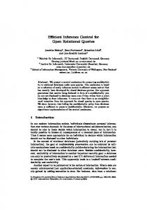
main memory, invoke basic driver processing, perform a context switching to the appropriate process (say “link state protocol”) handle the message and send a possible response. Typical numbers for this process are 9ms (Sparc 1) and 4 msec (DECStation). Recall that a switch embedded CP may not be as powerful RISC engine.This sets a practical limit to the number of flood updates that can be processed per second to somewhere around hundred or less. We have simulated the update rate of the link triggering update mechanism of PNNI in a network of 60 nodes and 240 links at average loads of 0.6-1.0. Our calls were divided to 3 classes in terms of calls duration (1-15 hours, 1 minute - 1 hour, and 0.5 second to 10 seconds, assuming uniform duration distribution within the range) and bandwidth range (1-20Mbps, 64Kbps-10Mbps and 1-10Mbps, respectively).The classes rep-
0.06 0.05 0.04 0.03 0.02 0.01 0
0
50
FIGURE 1. ACR_P M
Load 0.6
0.7
0.8
0.9
1.0
30%
.3439
.3980
.4208
.4670
.4912
40%
.2796
.3275
.3503
.3947
.4162
50%
.2284
.2703
.2915
.3320
.3515
60%
.1879
.2243
.2442
.2810
.2984
70%
.1537
.1850
.2038
.2365
.2527
75%
.1385
.1675
.1922
.2158
.2306
TABLE 1.
PNNI - Average updates rate, per link per second
resent backbone connections (PVCs and VPs), real-time video and audio and bursty data connection (WWW, FTP, NFS) respectively. The distribution among classes was 0.25, 0.25 and 0.5, respectively. PNNI uses an incremental reporting algorithm which triggers a new update only if the change in the available bandwidth. since the last update is at least ACR_PM% (but not less than 3% of the capacity). The results of Table 1 are in terms of average number of updates per link per second. For example for a load of 0.8 and an ACR_PM of 60% the total number of updates triggered per second is 0.2442*240=58.5. For backbone switches in the network that may have a link degree of 8 or more this amounts to the reception of at least 468 updates/second on average. For a more accurate (but still quite coarse) ACR_PM=30% the number rises to 808. Finally, recall that the average is not the worst case load. Given the possible correlation between the updates (a large call is being set up or released via multiple links) there is a non-negligible probability (0.02) for periods of update rates which are twice or more higher (see Figure 1). Therefore, a clear conclusion is that the PNNI utilization update mechanism is very inefficient and might result in periods of excessive CP loads even under moderate network sizes and update accuracies. A clear evidence is the recommendation of the PNNI standard to set ACR_PM at the level of 75%, which results in almost no meaningful utilization information. In contrast in OPENET, utilization update is received only once at a node and can be batched at any granularity level. Therefore, no matter how many such updates are received the CP may deal with all updates at its own chosen times.
100 Update Rate
150
Utilization rate distribution
The elected leader of the peer group is responsible for setting up and maintaining the utilization update distribution tree. When a topological change in the distribution tree occurs, the leader sends a tenure message (defined in PNNI) to all other nodes within the peer group. Every node that receives this message releases (locally) the distribution tree thereby stopping the forwarding of cells on this tree. Since the tenure message is sent using the reliable flooding mechanism, every node in the peer group will eventually receive this message and release the distribution tree. The leader will compute a new distribution tree and setup it anew. The details of the utilization unicell messages are described in [3]. Note that among the nine PNNI parameters only few are truly dynamic parameters that change as loads change over links. Most parameters are guaranteed for the whole duration of an established connections even if new connections are further added to that link. Therefore they must describe worst case values. Our utilization cells are programmed to carry any of the parameters the network operator would like to consider as “utilization data”. B. Route Computation Route computation is performed at the source CP of a connection or by another CP for third party setup. It needs to obtain a low cost (in terms of administrative weight) path (unicast) or tree (multicast) which meets the bandwidth and other QoS constraints (delay, loss) of the connection. According to PNNI, the link state parameters are classified into two classes, link metrics and link attributes. A link metric is a link state parameter for which the combination of all link parameters along a given path determines whether the path is acceptable for a given connection. A link attribute is a link state parameter that is considered link by link to determine whether the link is acceptable for carrying a given connection. OPENET currently regards the MCTD (maximal delay [4]) as an additive link metric. All other parameters are used as link attributes. A setup request for a unicast connection contains the bandwidth requirements and QoS class of the connection in both directions. The bandwidth requirements (the peak and sustainable cell rates) along with the link state parameters (ACR, CRM and VF) are used by the GCAC algorithm in [4] to deter-
6
CBR 10-50 CBR 2-10 ABR 10-50
ABR 2-10
UBR
FIGURE 2.
ABR 0-2
CBR 0-2 RT-VBR RT-VBR RT-VBR 2-10 10-50 N-VBR 0-2 0-2 N-VBR 2-10 N-VBR 10-50
Route computation instances
mine whether a given link can be considered in the route computation. The route computation then proceeds by finding the minimum weight path (according to the AW parameter) under the constraint that the sum of the MCTDs along the path does not exceed the requested MCTD of the connection. A fast setup process is extremely important for the success of ATM networks as discussed in Section II. A full computation of the route upon the receipt of a setup request can extensively delay the setup process. Hence in OPENET routes for different QoS classes and route capacities are pre-computed and stored. This allows the use of otherwise idle processor periods for route computation. OPENET uses precomputed routes for small bandwidth calls and on demand computation for very large bandwidth calls. OPENET computes 13 different instances of routes divided according to three bandwidth ranges and the QoS class of calls as depicted in Figure 2. Computation starts generally from high-bandwidth calls (as these routes can also be used to carry low bandwidth call) to low-bandwidth ones. Arriving calls are matched to one of the route instances. The cached route is checked and validated against the latest topology and utilization data (if necessary). If no valid route is found, an ondemand computation is carried on for that call. Another aspect of the routing algorithm is the way it adapts to changes of topology and utilization. OPENET has taken the approach that a single instance of route computation will not be interrupted in the middle due to topological changes (preventing “livelocks” as a result from excessive updates). Instead, the current computation instance will be completed and only then will the new topology information be integrated. The computation will continue retaining the same round robin order until all instances are derived using the new parameters. Routes for high bandwidth calls are always computed first. This approach guarantees that even in a frequently changing network, the routing algorithm can make progress and all QoS classes will be served by it. Our algorithm is a heuristic one based on several applications of Dijkstra’s shortest path algorithm each with a different set of edge weights [3]. Each application looks for an optimal set of paths with respect to one criterion using the others as constraints. The execution of the complete algorithm results in a set of feasible routes in terms of the delay requirements. This set of routes is stored as an ordered set of subtrees (which is a natural outcome of Dijkstra’s algorithm).
V. OPENET Signalling A. Forwarding modes OPENET defines low level communication mechanisms termed forwarding modes, by which CPs forward control messages to other non-neighboring CPs. The source route and VC traversal forwarding modes described in this section allow a CP of switch s 1 to forward messages to the CPs of switches s 2, …, s n in a given order. Other forwarding modes (such as the use of the distribution tree, or employing the ATM F5 flow) are being considered as future extensions. Source Route Forwarding Mode In the source route forwarding mode a message traverses a path from CP to CP according to a route that is explicitly contained within the message [8]. The path is described by a sequence of local link/port IDs. A CP along the path not only forwards the message to the next CP along the path but also performs an individual function that is also indicated in the list. Such a message is used, for example, by the VC set-up mechanism in which the typical function would be bandwidth reservation. Source route forwarding is also used for general datagram delivery between CPs, i.e., delivery of messages with no connection setup. Not all CPs along the path have to perform the same function nor must the path be a simple one. Thus, for example, one can construct a path from, say, CP 1 to CP 2 and back to CP 1 in a way that different functions or none are performed by the CPs in the forward and backward direction. For example, one can use such a message for the construction of a VC in which the initiator of the setup operation is not the source of the VC (third-party setup). The source routing mode also allows to trace back the path the arriving message took. The reverse path is optionally accumulated by replacing the current forward path port by the backward ones at each hop. In this case, an arriving message can be responded to over the same path it has arrived on. The forwarding mechanism is based on a list of port IDs (and an optional function per ID) included at the header of the message. A pointer variable which precedes this list points to the particular link ID of the current hop. The pointer is advanced by the node to the next position before the message is forwarded. If the reverse path accumulation indicator is set, each intermediate node replaces the already consumed link ID (incoming to this node) by the ID of the outgoing link the message was received from. A second indicator termed direction instructs the node to follow the link list in particular direction, either incrementing or decrementing the pointer at each hop. VC Traversal Forwarding Mode In the VC traversal forwarding mode a message traverses a path hop-by-hop from one CP to another along the route of a previously established VC, i.e., the control message is forwarded from a CP to a CP along the VC route without having its cells being carried over that VC. A VC traversal message can traverse any type of VC, including multicast VCs and distribution trees. Since the CP keeps a version of the local VC table(s), it is possible for CPs to exchange control messages
7
along VC path by examining the entries of its VC table and swapping the appropriate VC identifiers, emulating in software the actions performed by the switch itself. The method of forwarding control messages from a CP to a CP along the path of an existing VC described above is referred to as the Forward VC Traversal or simply VC Traversal. VC traversal can also be carried on the opposite direction based on the output labels. This is referred to as the Reverse VC Traversal [3]. B. Connection Control and Maintenance The main tasks associated with connection control are connection setup, connection take down and connection maintenance. The OPENET connection setup uses the source route forwarding mode and includes the update of routing tables and the bandwidth reservation along the chosen route. It utilizes end-to-end error recovery in order to lower the overhead in typical error-free cases. The connection can be either a unicast, a single source multicast, or a multi-source multicast (distribution tree). OPENET provides third party connection setup capability [3]. Connection clearing (take down) is used for bandwidth and label release upon the termination of calls, or upon topological outages that disconnect the connection. Connection maintenance is needed to modify the parameters of existing connections and to insure “soft state” operation of the network to release of unused resources in cases of undetected errors. OPENET uses light-weight protocols based on the optimistic approach guideline. In the following we outline the main ideas behind these operations, more details can be found in [3]. Unicast Connection Setup and Clearing A unicast connection setup is initiated by a user that sends its CP a UNI SETUP message [5] that includes the destination address, the class of service it requires and other parameters. In OPENET traffic intensity is represented by a region of acceptable values MAX and MIN, allowing the user more flexible decisions based on network state. The CP computes a feasible route as described earlier. The CP then constructs an N_SETUP message (defined by OPENET [3]), using the source route forwarding mode. The message contains, in addition to its type and route, the range of bandwidth parameters, the function to be performed by every link and label fields that are swapped by the corresponding CPs along the route. It also carries the relevant end-to-end parameters. The N_SETUP message is then forwarded downstream from the source CP to the destination CP. Each CP that receives the N_SETUP message checks whether the corresponding switch can accommodate the connection, possibly updating the MAX value. When an N_SETUP message arrives at the destination CP, it sends a UNI SETUP to the destination host and generates a N_SETUP_ACK message that is forwarded upstream back to the source CP along the same route of the established connection. The N_SETUP_ACK message, which is of the forward VC traversal type, contains the final MAX value contained in the N_SETUP message just arrived. Upon receiving an N_SETUP_ACK message, each CP along the reverse path updates the bandwidth reserved for the con-
nection, updates the label fields and records it in the switch. When the message arrives at the source CP, the connection is now ready. The source CP then sends an N_CONNECT_ACK to the destination to notify that the connection is ready. In normal operation of the network, clearing operations are needed to release reserved bandwidth upon the users requests to terminate connections. In addition, clearing operations are needed to release reserved resources when failures cause the disconnection of the source from its destinations. The clearing protocol is responsible for returning the used VC labels as well as bandwidth to the unused pool. Ours is a ‘one pass release protocol’, based on the VC traversal mode. Each CP that receives the release message releases the corresponding bandwidth at the appropriate switch, erases the corresponding entry from the VC table and forwards the message (see [3]). Unicast Connection Maintenance OPENET supports the changing of reserved bandwidth in a connection. The N_CHANGE message is used to change the reserved bandwidth along a path. It is always possible to lower a bandwidth requirement but the increase in bandwidth is on an availability basis. The N_CHANGE message (VC traversal) contains the MAX and MIN bandwidth desired for this connection and a refresh period value. The N_CHANGE message is acknowledged by the N_CHANGE_ACK message, which contains the final negotiated value and is also of the forward VC traversal type. Connection maintenance is also used as a “garbage collection” mechanism that prevents loss of resources following undetected errors. These events are rare, and therefore the connection maintenance is based on the source CPs sending at a very low rate periodic refresh messages. The refresh messages (N_CHANGE messages with the same bandwidth parameters) allow the intermediate CPs along the connection to slowly age the connection and eventually take it down if not refreshed within the connection refresh period. In this case the CP concludes that the connection has been disrupted, and will start a clearing procedure. The refresh period is not uniform for all connections. High bandwidth connections may use more frequent refresh messages than “light” connections. The N_CHANGE and N_CHANGE_ACK messages are simple and contained within a single cell. Multicast Connection Setup and clearing A multicast connection setup is initiated by a user when it needs to communicate with several other users in the network. The host sends its CP a request that contains the destination addresses, rate and the QoS it requires. As in the unicast case, the CP maps this to a network class of service along with a MIN-MAX representation of traffic intensity. The CP then computes low cost feasible routes for the corresponding constraints. These routes form a tree rooted at the source host and each of its leaves is a destination hosts. OPENET supports and extends the setup of multicast connections defined by UNI 4.0 by providing two ways to set up a multicast VC. The first method, called complete setup, is based on a single setup message that traverses the whole tree and cre-
8
ates a multicast tree using a single message. The second termed incremental setup, is based on several unicast like setup messages (that may partially overlap). The incremental method allows the root to add destinations to the multicast tree one at a time as in UNI 4.0. In the complete setup case, the source CP computes a traversal path of the tree. This path starts and ends at the source CP, and traverses each link of the tree exactly twice. The setup process is achieved by an N_SETUP message of the source traversal route type which include the traversal list, the function to be performed by every link, the label field and the MIN and MAX values, much like the unicast N_SETUP message. For a list of the possible functions in the multicast case see [3]. The N_SETUP message completes the traversal back at the source CP. The MAX value contained in this message is the final acceptable value at all nodes in the multicast tree. The source CP issues an N_CHANGE message to notify all CPs of the final accepted bandwidth. The N_CHANGE message is broadcast over the tree using the VC traversal mode. Each CP then adjusts the reservation to the final accepted value. The N_CHANGE message is acknowledged by all leaf CPs with the N_CHANGE_ACK message, which confirms and completes the multicast connection setup. The incremental setup is a combination of multiple unicast setup (see [3] for details). Unlike a unicast connection, a multicast connection may be partially taken down, for example, when one end-user decides to remove itself from the multicast or when a failure caused the tree to be partitioned. There are two basic clearing operations. A complete take down of the entire connection is termed connection release. A partial take-down of a connection is referred to as a user drop operation, which can be a root-originated or a leaf-originated request. It is required (at both UNI and OPENET) that the originating user stays connected at all time. OPENET uses unicell messages and VC traversal for accomplishing the various multicast connection clearing ([3]). Multicast Connection Maintenance Changing the reserved bandwidth of a multicast connection is similar to unicast connections. Only the source of the multicast connection can send an N_CHANGE message to increase or decrease the bandwidth of the connection. This N_CHANGE message includes the minimum and maximum bandwidth desired for this connection and a refresh period. The change message is acknowledged by N_CHANGE_ACK messages that contains the final negotiated values from each of the end-point CPs. If all parties agree on the final values, the change is completed. Otherwise, another N_CHANGE message with the smallest value among all parties has to be sent. Success is guaranteed over each link of the multicast connection as every link has reserved at least that value. Distribution Tree Setup As described in Section III, distribution tree may be constructed using either a pivot-based or a load-balanced tree approach. In the pivot-based case, the distribution tree consists of a root CP (the pivot), a destination tree and a source tree. In the load-balanced tree case, each node behaves as if it were the
pivot, such that cells arriving at any node will be distributed over all outgoing links except the one from which they come. In general, the sets of source CPs and destination CPs may be different. However, in the distribution tree that is used to distribute the utilization updates, each of the two sets contains all the CPs in the network. In the following we focus on the setup of the distribution tree that is used for utilization update. In the load-balanced tree based distribution tree setup, an arbitrary CP is chosen as the root of the tree. The root CP then conducts the set-up procedure based on the complete multicast setup method. The root CP first assembles an N_SETUP message with a complete traversal of the distribution tree. The operation at each CP is also similar to that of a multicast tree. However, at the last visit of the message at each CP it is instructed to update the switch VC tables as required using a special function in link ID list of the N_SETUP message. In the pivot based distribution tree setup, a CP is first chosen as the pivot and coordinates the setup. The pivot CP computes source and destination trees.These two trees are set up independently and then merged at the pivot to form a distribution tree. We can use either the single message or the multiple messages multicast setup approach. Once the pivot completed its set-up operation it makes the final change in its switch VC table to connect the local source tree incoming VC indicators to the local destination outgoing VC indicators. VI. References [1] R. Handle, M. Huber and S. Schroeder, “ATM Networks, Concepts, Protocols, Applications,” Second edition, Addison-Wesley, 1994. [2] I. Cidon, I. Gopal, M. Kaplan and S. Kutten, “A Distributed Control Architecture of High-Speed Networks,” IEEE Trans. on Comm., Vol. 43, pp. 1950-1960, May 1995. [3] I. Cidon, T. Hsiao, P. Jujjavarapu, A. Khamisy. A. Parekh, R. Rom and M. Sidi, “The OPENET Architecture,” SUN Microsystems Labs report, SMLI TR-95-37, Dec. 1995. (http://www.sunlabs.com/smli/technical-reports/1995/ smli_tr-95-37.ps) [4] PNNI SWG, “PNNI Draft Specification” ATM Forum Contribution 94-0471R7. [5] ATM Forum, “ATM User-Network Interface Specification”, Version 3.0, Prentice Hall 1993. [6] A. Baratz, J. Gray, P. Green, J. Jaffe and D. Pozefsk, “SNA Networks of Small Systems,” IEEE Journal on Sel.Areas in Comm., Vol. 3, pp.416-426, May 1985 [7] R. Cohen, B. Patel, F. Schaffa and M. Wiilebeek-LeMair, “The Sink Tree Paradigm: Connectionless Traffic Support on ATM LANs,” Proc. of IEEE INFOCOM’94, pp. 821828, Toronto, Canada, June 1994. [8] I. Cidon and I.S. Gopal, “PARIS: An Approach to Integrated High-Speed Private Networks,” Int. Jou. of Digital and Ana. Cab. Syst.s, Vol. 1, pp. 77-86, April-June 1988. [9] J. Moy, “OSPF Version 2”, Network Working Group, Internet Draft, September 1993