Operating characteristics of unit and group connected generator-HVDC converter schemes. J. Arrillaga, DSc, FlEE. J.R. Camacho, MSc. S.J. MacDonald, BEng.
Operating characteristics of unit and group connected generator-HVDC converter schemes J. Arrillaga, DSc, FlEE J.R. Camacho, M S c S.J. MacDonald, BEng C.P. Arnold, PhD, MIEE
Indexing t m : Group connection,HVDC conwrtets, Loadpow, Unit connection
Abstract: The two alternatives for the direct connection of generators to HVDC converters, i.e. the unit and group connections, are compared under varying study-state operating conditions at nominal operating frequency. Direct connection is dehed as the connection of synchronous generators and converters without AC filters and with the transformer having simultaneously the function of converter and step-up transformer. With all the units in service both schemes display the same characteristics. By reducing the number of generators in m i c e the group connection bccomes more efficient at lower power levels. The opposite effect occlvs with the unit connection where the efikiency reduces with the power levels, particularly with fewer generators in service. Moreover, in the last-mentioned case the inverter end of the link requires extra reactive power compensation. Therefore for s&emes operating at varying power levels and fixed frequency the group connection should be the preferred alternative.
List of symbols
= rectifier AC system EMF = rectifier AC system commutatingvoltage = Unitconnection commutating reactance = Groupconnection Commutating reactance = generator synchronous reactance
= generator sub-transient reactance = converter transformer reactance
V.
V, V, V, 'V
= reactance base in ohms = total number of generators = number of generators in service = direct voltage for one unitconnected generator = direct voltage for n, generators = inverter end voltage per pole of link = rectifier end voltage per pole of link
= base voltage in kV MVA,= MVA basc = direct current of link I, = phase current for unit-connected scheme I,
Q IEE 1993 Paper 9602C (p9, PlO), !kat received 27th Novcmber 1992 and in rcviscd form 30th March 1993 The author8 are with the Department of Electrical and Elcctroaic Engi-#, UnivcrSity of Canterbury,christchurch, New Zealand. IEE PROCEEDINGS-C, Y d . I&, No. 6,NOVEMBER I993
R = resistance per pole of link R(n) = residuals in AC-DC load flow r = voltage ratio of converter transformer a a
/3
4 y
q,
q, qy qf qy qf 1
= tap of converter transformer = converter firing angle = phase angle of commutating voltage
= power factor angle in primary of converter trans-
former
= converter extinction angle = turbine effciency = transmission efficiency = transmission efficiency, unit connection = transmission efficiency, group connection = overall efficiency, unit connection = overall effciency, group connection
Introduction
Several contributions have discussed the direct connection of generators to HVDC converters. Some have tried to justify the adoption of the unit-connection concept on the basis of substantial cost reductions in power generation and rectification plant [l-31. Others have described the development of computer models for the incorporation of the unit connection in power system studies ~ 451. , An important disadvantage of the unitconnected scheme is a considerable increase in the number of converter transformers, i.e. two per generator for 12-pulse operation. Consequently a 600 M W (6 x 100 MW units) power station requires 12 converter transformers as compared with only two for the conventional rectifier station.The general cases of n generators connected either as units or as a group are shown in Fig. 1. The possibility of six-pulse operation, which only requires one transformer and bridge per gene-rator, is not considered because of the extra characteristic harmonic problem in the generator and in the DC l i e . Operation of the unitconnection configuration with diode rectifier bridges was considered in previous published articles [3,4], which show the operational limitations and possibilities of operation of a converter Financial assistance has been provided by the New Zealand Ministry of External Relations and Trade, New W a n d Vice-Chancellors' Committee, by Universidade Federal de UberlPndia Departamento de Engenharia Elktrica and by
503
under minimum firing angle equal 0". The power transmission setting may be determined by the receiving system requirements and generating efficiency. Therefore,
requirements. The results of such investigation are described here. Steady-state analysis
2
1
2
I
YA
YY
!
-
An accurate power flow solution of the unit-connection scheme with representation of saliency effects requires the use of time domain calculated rectifier characteristics [a]. However for a preliminary comparison of the characteristics of unit- and groupconnected schemes the conventional AC/DC steady-state power flow [8] provides sufficient information. By assuming that all the generators in service have identical characteristics and are equally loaded, they can be represented as a single equivalent machine as in Fig. 2.
0
Fig. 2
b
Fig. 1
Generator-conwter plant
a Unir-couatctedgoamration
b Group-munectedpemtiou
the number of generators in service will vary if the generating plant has been designed for constant (nominal) speed operation. This could be avoided with the use of variable-speed turbines which will permit optimal efficiencies at varying water heads. The question of direct voltage control at low speeds (and frequencies) has been considered in a recent pubwhich shows that constant-voltage transmislication sion can be achieved even without the need for on-load tap changers at the rectikr end. The disconnection of generating units, while ensuring efficient generation, may result in poor transmission efficiency when applied to unit-connected schemes because the voltage is proportional to the number of units connected in series. Moreover, transmission voltage reductions caused by the disconnection of units at the rectifier end will immediately be followed by corresponding firing angle advances at the inverter end, which may require extra VAr compensation. These problems should not affect the direct group connection of generators to HVDC converters because the generators are paralleled at a common converter busbar and all the converter units in series remain in service following generator removals. At a time when direct connection is being seriously considered, it is important to compare the operating characteristics of the two alternatives, i.e. unit and group configurations, and assess their effect on the overall system efficiency and receiving end reactive power
[a
504
Test system I rectifier end oflink
The internal EMF behind subtransient reactance is not directiy controllable. Instead, the generator excitation will be controlled to provide the specified DC link power at the specified firing angle (d. With rekrence to Fig. 2, the fictitious bus behind the machine's subtransient reactance is used as the slack busbar on the rectifier si& of the load flow solution and the subtransient voltage is used as the commutating voltage for the converter. However the commutating voltage (E") is not known in advance and its magnitude and phase 0 are obtained as part of the load flow solution. The vector of independent variables of the converter model is [4] where T is its transpose. Seven residual equations were needed to formulate the load flow problem at the rectifier end. The first two equations are common to the conventional model [a] (withtap variable removed). Therefore, R(l) = V, - kIE" COS 4 (2) 3 R(2) = V, - k,E" cos a - - I,x,
(3)
where kl = 3,/(2)/x. The next two are derived from the generator subtransient phasor diagram of Fig. 3. That is,
- E" COS B - (X - x")I(I,I sin (B + 4) R(4) = E" sin B -(x - x")lI,lcOs (B + 4) R(3) = E
(4)
(5)
Valid converter control specificationsare: direct voltage, direct current, minimum firing angle and DC power at the receiving end. To solve for the seven variables of eqn. 1 three of them must be specified. The second and third specifications will normally be the direct voltage and current fixing the DC power at the rectifier end. However, once the control angle a reaches the minimum level amh, this value becomes the second specification instead of the direct voltage. The incorporation of converter equations into the AC/DC power flow solution is IEE PROCEEDINGS-C, Vol. 140, No.6, NOVEMBER 1993
well documented and the results obtained in this paper are based in the algorithms described in References 4 and 8.
ators in service. The reverse happens in the case of the unit connection (eqn. 8), where the commutation reactance and hence the slope of the voltage regulator remains invariant while the open-circuit voltage reduces with the number of generators in seMce. 3
E
Fig. 3 ator
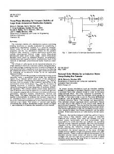
The generator excitation will be designed to keep the converter voltage constant under different specified powers. For the unit-connection configuration however, with a reduced number of units in operation, the exciters of these machines will not be able to maintain the nominal transmission voltage level. Once the maximum excitation is reached the commutating voltage (i.e. E") will reduce with increasing current and therefore the output VdI, characteristic of the rectifier will be nonlinear. The AC/DC load flow, described in Section 2, is used to derive the rectifier characteristics of the unit and group connections. The results for the test system specified in the Appendix are shown in Fig. 4 and 5. Points a tofand
Simplified phasor diagram of unit and group-connected gener-
Figs. l a and b display the main components of the two basic unit and groupconnection configurations. It is assumed that all the generators are the same and equally excited. If r is the converter transformer voltage ratio of the unit connection, then to derive the same nominal direct voltage and current, the corresponding ratio for the groupconnection transformers needs to be rn, where n is the total number of generators. Using as a power base the nominal rating of one generator, the commutation reactance of the unit-connection bridges is x,-, = x"
+ 2x,
Rectifier characteristics
(6)
or x, = (x"
+ 2x,)xBr2
(7)
in ohms, where x, = V$MVAB, with V, being the base voltage at the primary side of the transformer. The direct voltage of a twelve-pulse bridge unit is
direct current, k A
Fig. 4
Charaetrrirtifs for Unit-mnected generation at rectifier end
- 6machincs ____
5 4
___..__ 3
and the total direct voltage output with n, generators in service is V,=n,V,
__
2
(9)
i.e. the output is always proportional to the number of generators in service. Using the same power base, the commutation reactance of the groupconnection bridges with n, generators in service is
or 0
in ohms, and the maximum direct voltage of the group connection is
0.2
0.4
0.6
0.8
10
12
1.4
direct current, k A
Fig. 6
.. . . . . .
~
Charactnisticsfor groupconnected generation at rectifier nd dmnshinn
____
___..._
Eqn. 12 shows that for a given excitation the no-load voltage output remains invariant regardless of the number of generators in service. However, the second term of the equation depends on n, and therefore the slope of the voltage regulation increases with fewer generIEE PROCEEDINGS-C, Y d . 140,No. 6,NOVEMBER I993
__
1
a' tof' in those Figures indicate the nominal operation of
the test system when changing the number of machines in service from 6 to 1, respectively. 505
With all the generators in service the unit and group configurations follow the same characteristic. In both c~sesthe intersection of this curve and the maximum specified power level (PI = 520 MW)(i.e. point a) determines the operating current required (i.e. 1.16 kA in the test system). At a reduced power setting (P2= 430 MW) and with one generator removed, the unit and group characteristics are different, giving rise to the operating points b in Fig. 4 (1.15 kA) and 5 (0.955 kA), the last requiring less Current and thus resulting in better transmission cfEciency. Although the commutation voltage loss is larger in the case of the group connection, the reduced open-circuit voltage of the unit connection demands more current for a given power setting. Further generator removals result in operating points c, d, e and f in Figs. 4 and 5, which show a practically constant voltage for the case of the group connection. For these points the currents in Fig. 4 are, respectively, 1.125, 1.1, 1.09 and 1.01 kA. In Fig. 5 the currents for the same points are 0.75, 0.55,0.35 and 0.153 kA. The curved lines are the VJr, characteristics for the rectifier in Figs. 4 (unit connection) and 5 (group connection) and for the inverter in Fig. 6 (unit and group connection). Table 1 ~~~
Number of Power Power machines d v e d desionation
3
P,
430 340
p2 p3
250 160 70
2 1
P, P, P,
Inverter characteristics
In Fig. 6 the constant-power characteristics are combined with the inverter constant extinction angle characteristics
0
0.2
0.4
06 0.8 10 direct current, kA
ChactrrisrieJ /or
Fig. 6
w’t- and
12
group-connected generation at
- dnurhiw
. ......
5
3
______*
__
2
to give the same operating points described in the p r e vious section, after taking into account the effect of Dc line resistance. Clearly, in the unit-connection case a 506
360
480
octive power. MW
Fig. 7
Power characteristics for unit-conteftedgeneration at inverter
end
- LI11.Chiaa
the inverter end for different numbers of unit-connected machines at the rectifier. The difference between the rea0 tive demands with 6 and 5 machines is small (points a‘ and b’, respectively) becaw the complete range of tap variation is first used to delay the extra reactive demand with one machine d i ~ ~ e ~ t Once e d . the tap change range is exhausted such demand increases fast. For instance when changing from six to four machines (points a’ and c’, respectively) the inverter reactive power increases from about 210 to 320 MVAr. On the other hand, the group connection permits operation with fewer generating units in service while reducing the inverter reactive power demand. This is illustrated in Fig. 8 where the reactive versus active
0
1.4
inverter end
____
240
120
-_
shows the maximum power at the receiving end for each number of machines in operation. 4
0
... . ... 5 _.-____ 3
_ _ _ _ _ _ _ ~
6 5 4
reduces the transmission voltage and transfers the constantarrent control from the rectifier to the inverter end which then operates with increasing firing angle advances and reduced power factors. This is illustrated in Fig. 7 which shows reactive versus active power levels at
____
Tabla 1 : Maximum wmr r . u i v d at inverter end
MW 520
gradual reduction in the number of generating units
im
210
3 6 o m
active power, MW
Fig.8
Power charact&itiw
for groupconnected generation at
inverterend
- 611ucba
... . ... 5 4 ._-___. 3
____
__
1
power characteristics with different number of machines are practically coincident. In this case a 3.2% tap variation of the inverter end t r a n s f o ~can accommodate IEE PROCEEDINGS


![Connected Things [Bits Versus Electrons] - IEEE Xplore](https://m.moam.info/img/260x300/connected-things-bits-versus-electrons-ieee-xplore_5c39eeef097c476f5c8b4644.jpg)