Sep 30, 2011 - and available laser sources, the operating plasma density will be optimized. We note ...... calculations are in good agreement with the analytical.
PHYSICAL REVIEW SPECIAL TOPICS - ACCELERATORS AND BEAMS 14, 091301 (2011)
Operating plasma density issues on large-scale laser-plasma accelerators toward high-energy frontier Kazuhisa Nakajima,1,2,3 Aihua Deng,1 Xiaomei Zhang,1 Baifei Shen,1 Jiansheng Liu,1 Ruxin Li,1 Zhizhan Xu,1 Tobias Ostermayr,4 Stefan Petrovics,4 Constantin Klier,4 Khalid Iqbal,4 Hartmut Ruhl,4 and Toshiki Tajima4,5 1
Shanghai Institute of Optics and Fine Mechanics, Chinese Academy of Sciences, Shanghai 201800, China 2 High Energy Accelerator Research Organization, 1-1 Oho, Tsukuba, Ibaraki 305-0081, Japan 3 Shanghai Jiao Tong University, Shanghai 200240, China 4 Ludwig-Maximilians-Universita¨t Mu¨nchen, 85748 Garching, Germany 5 Max-Planck-Institut fu¨r Quantenoptik, 85748 Garching, Germany (Received 14 July 2011; published 30 September 2011) Consideration of laser-driven plasma-based electron/positron accelerators with a 2 TeV center-of-mass energy is presented, employing a multistaging scheme consisting of successive multi-GeV laser wakefield accelerators operated at the plasma density range of 1015 –1018 cm�3 in the quasilinear regime. A total accelerator length is determined by an operating plasma density and a coupling distance allowed for both laser and beam focusing systems. We investigate beam dynamics and synchrotron radiation due to the betatron oscillation of the beam in laser-plasma acceleration, characterizing the beam qualities such as energy spread and transverse emittance. According to the criteria on the beam qualities for applications and available laser sources, the operating plasma density will be optimized. We note that in the low density operation the required wall-plug power for the laser driver will be much reduced in comparison with the high-density options. DOI: 10.1103/PhysRevSTAB.14.091301
PACS numbers: 41.75.Jv, 52.38.Kd, 52.40.Mj
I. INTRODUCTION In the past decades, thanks to vital experimental and theoretical research, the development of laser-driven plasma-based accelerators (LPAs) has evolved from a groundbreaking concept [1] into the reality of the next generation accelerator technologies. This promises compact accelerator applications such as radiolysis [2], possible electron diffraction [3], interactive radiotherapy [4], and radiation sources of THz [5] and other domains [6]. In particular, it will allow us to downscale large-scale particle accelerators such as x-ray free electron lasers and high-energy frontier colliders into a realistic size in both dimensions and costs. Initiating the proof-of-principle experiments [7], the previous LPA experiments have demonstrated production of electron beams with high energies of GeV level [8,9], high qualities of 1%-level energy spread [10], 1-�mm-mrad-level transverse emittance [11], and 1-fs-level bunch duration [12], ensuring that the stability of reproduction is as high as that of present high-power ultrashort-pulse lasers with controlled injection [13]. Most of the experimental results have been obtained from interaction of ultrashort (30–80 fs) laser pulses with a shortscale plasma such as a few mm long gas jet and at most a few cm long plasma channel at the plasma density in the
Published by the American Physical Society under the terms of the Creative Commons Attribution 3.0 License. Further distribution of this work must maintain attribution to the author(s) and the published article’s title, journal citation, and DOI.
1098-4402=11=14(9)=091301(12)
range of 1018 –1019 cm�3 , where a large-amplitude plasma wave of the order of 100 GV=m is excited and traps energetic electrons to be efficiently accelerated inside a wake to high energies of the order of 1 GeV. The leading experiments that demonstrated the production of quasimonoenergetic electron beams [14] have been elucidated in terms of self-injection and subsequent acceleration of electrons in the nonlinear wakefield, often referred to as a bubble [15], that is a region where plasma electrons are blown out by radiation pressure of a laser pulse with the relativistic intensity given by its normalized vector potential a0 ¼ eA0 =me c2 � 1, where A0 is the peak amplitude of the vector potential and me is the rest mass of electron. The self-injection is a robust method relying on self-focusing and self-compression that occur during the propagation of relativistic laser pulses with the threshold power ðP=Pc Þth � 3 [16], where Pc ’ 17ð!0 =!p Þ2 GW is the critical power for the relativistic self-focusing with the laser frequency !0 and the plasma frequency !p ¼ ð4�e2 ne =me Þ1=2 . In this mechanism, initially heated electrons with large transverse momentum are injected into the nonlinear wakefield with strong focusing field that induces betatron oscillation of accelerated electrons. Hence, suppressing the self-injection and the betatron oscillation, high-quality electron beams required for most of the applications have been produced with controlled injection schemes such as colliding optical injection [17], density-transition injection [18], ionization-induced injection [19], and two stage laser-plasma accelerator with ionization-induced injection [20] in the quasilinear regime
091301-1
Published by the American Physical Society
KAZUHISA NAKAJIMA et al.
Phys. Rev. ST Accel. Beams 14, 091301 (2011)
of wakefields driven by a laser pulse with a moderate intensity a0 � 1. These injection technologies provide us with GeV-class high-quality electron beam injectors. Since an acceleration length of a single-stage LPA is limited by a dephasing length where accelerated particles overrun a correct accelerating phase and/or n energydepletion length of a drive pulse, applications of LPA for high-energy frontier accelerators with a beam energy exceeding energy gain in a single stage require multistage technologies, following the analogy of conventional rf accelerators. In contrast with the rf accelerators of which wavelength is the order of 10 cm, a temporally and spatially coherent matching between successive LPAs operated at the plasma density of ne ’ 1017 cm�3 , corresponding to the wavelength of the order of 100 �m, is a challenging technology, which has been never accomplished as well as an efficient coupling technology injecting ultraintense laser pulses into the LPA stages. The overall length of a large-scale LPA consisting of periodic structures of a coupling section and a plasma accelerator can be determined by the single-stage energy gain for a given beam energy. The operation at a low plasma density increases the single-stage energy gain, while it reduces the accelerating gradient and increases the pump depletion length Lpd , i.e., the single-stage plasma length Lstage with Lstage � Lpd . Minimizing the overall linac length leads to the operating plasma density at ne ¼ 1017 cm�3 for the beam energy 0.5 TeV, the drive laser intensity a0 ¼ 1:5, and the coupling distance � 1 m [21]. The coupling section that installs both laser and beam focusing systems might require a distance of the order of several meters, employing the coventional technologies for the TeV regime. Furthermore, applications of the multistaged LPA for the high-energy physics experiments require extreme high-quality beams with small energy spread and transverse emittance as well as sufficient charge. These requirements reduce the optimum operating plasma density toward the order of ne ’ 1015 –1016 cm�3 rather than 1017 cm�3 , at which the operation of the LPA linear collider has been previously conceived [21,22]. The technology preforming a large-scale plasma channel also limits the plasma density to the range of 1015 –1016 cm�3 . Since the degradation of energy spread and transverse emittance is inevitably induced by dephasing and betatron oscillation of accelerated beam particles that undergo strong accelerating and focusing wakefields in the multistaged LPA [23,24], compromising between the linac length and the beam-quality requirements allows us to find the proper operating plasma density. In this paper we consider the design of the multistaged LPA, composed of the LPA stages each of which is operated in the quasilinear laser wakefield regime characterized by a0 � 1. The formulas for designing a single stage are obtained as a function of the operating plasma density and the design examples of the LPA linac with the beam energy
of 1 TeV are presented at the operating plasma densities of 1015 –1018 cm�3 in Sec. II. Considering the beam dynamics, analytical estimates for the degradation of energy spread and transverse emittance including the synchrotron radiation energy loss are evaluated in Sec. III. For the application to high-energy electron-positron colliders, the requirements of luminosity and power are considered in terms of the plasma density in Sec. IV. The design formula and scalability on the plasma density for the single LPA stage are confirmed by scaling the 2D particle-in-cell simulations, carried out in the range of the plasma density of 1018 –1019 cm�3 in Sec. V. Based on the design examples of the TeV LPA linac, we deliberate on optimization of the operating plasma density and technological aspects in Sec. VI. II. MULTISTAGE LASER-PLASMA ACCELERATORS A. Accelerating field In underdense plasma, an ultraintense laser pulse excites a large-amplitude plasma wave and the accelerating electric field on the order of E0 ¼ me c!p =e ’ 96 ½GV=m� � ðne =1018 ½cm�3 �Þ1=2 due to the ponderomotive force expelling plasma electrons out of the laser pulse and the space charge force of immovable plasma ions restoring expelled electrons on the back of the ion column remaining behind the laser pulse. Since the phase velocity of the plasma wave is approximately equal to the group velocity of the laser pulse vg =c ¼ ð1 � !2p =!20 Þ1=2 � 1 and the accelerating field of �1 GV=cm for the plasma density �1018 cm�3 , electrons trapped into the plasma wave are likely to be accelerated up to �1 GeV in a cm-scale plasma. In the linear wakefield regime characterized by the normalized peak intensity of the linear polarized laser pulse a0 ¼ 0:85ðI�20 =1018 ½Wcm�2 �m2 �Þ1=2 � 1, where I is the laser peak intensity and �0 ¼ 2�c=!0 is the laser wavelength, the maximum accelerating wakefield driven by a Gaussian laser pulse with 1=e half-width �z is given by pffiffiffiffi � 2 2� kp �z � 2 : a0 E0 kp �z exp � EM ¼ 4 4
(1)
For a given plasma density, the maximumpfield ffiffiffi is EM � 2 0:38a0 E0 at the resonant condition kp �z ¼ 2 while, for a given pulse duration, the maximum field is EM � 0:33a20 E0 at the resonant condition kp �z ¼ 2. Changing both plasma density and laser pulse duration, the optimum condition turns out kp �z ¼ 1 for which the maximum field is EM � 0:35a20 E0 . The maximum wakefield is approximately given as
091301-2
EM ½GV=m� � 10:6a20
� 1017
ne ½cm�3 �
�1=2
;
(2)
OPERATING PLASMA DENSITY ISSUES ON LARGE- . . . pffiffiffiffiffiffiffi for kp �z ¼ 1, the FWHM pulse length c�L ¼ 2 ln2�z � 0:265�p , which means a laser pulse is shorter enough than a half plasma wavelength so that a transverse field at the tail of the laser pulse is negligible in the accelerating phase of the first wakefield. The net accelerating field Ez that can accelerate a bunch containing the charge Qb ¼ eNb , where Nb is the number of particles, is determined by the beam loading that means the energy absorbed per unit length, � � me c2 E2M 2 2 E2z k r 1� 2 ; Qb Ez ¼ 8re E20 p b EM
(3)
where re ¼ e2 =me c2 is the classical electron radius and 1 � E2z =E2M � �l is the beam loading efficiency that is the fraction of the plasma wave energy absorbed by particles of the pbunch ffiffiffiffiffiffiffiffiffiffiffiffiffiffiwith a radius rb . With the beam-loaded field Ez ¼ 1 � �l EM , the loaded charge is given by � �1=2 e �l 2 2 Ez nc k r Qb ’ 8k0 re 1 � �l p b E0 ne � ��1=2 �l E ne � 116 ½pC� k2p r2b z ; (4) 1 � �l E0 1017 ½cm�3 � pffiffiffiffiffiffiffiffiffiffiffiffiffiffi where Ez =E0 ¼ 0:35a20 1 � �l for kp �z ¼ 1. Since the loaded charge depends on the accelerating field and the bunch radius, it will be determined by considering the required accelerating gradient and the transverse beam dynamics, which will be considered in Sec. III. B. Stage length, energy gain, and total linac length The total linac length for the beam energy Eb is given by Ltotal ¼ ðLstage þ Lcoupl ÞEb =Wstage , where Lcoupl is the required coupling distance for injecting a new drive laser pulse and a beam into the next LPA stage, Wstage � Ez Lstage is the energy gain in the single stage, and Lstage is the single-stage plasma length. Ideally, the stage length may be determined by the pump depletion length Lpd over which the total field energy is equal to half the initial laser energy. For a Gaussian laser pulse with the pulse length kp �z ¼ 1, the pump depletion length is given by � 2 2� kp �z 8 !20 7:4 n � 2 c: kp Lpd ’ pffiffiffiffi 2 exp (5) 2 2 a0 ne �a0 kp �z !p ¼ffiffiffi 11ðnc =ne Þ The pump depletion length becomes kp Lpd p for a0 ¼ 1 and kp Lpd ¼ 3:7ðnc =ne Þ for a0 ¼ 2. Since the dephasing length is approximately given by kp Ldp ’ �ðnc =ne Þ or Ldp ’ ð�p =2Þðnc =ne Þ, where the electrons will undergo both focusing and acceleration in the linear wakefield regime, the single-stage energy gain can be limited by the dephasing length Ldp � 0:85Lpd . The 1D numerical analyses of the laser energy depletion show that a fraction of the laser energy depletion over pffiffiffithe dephasing length is 15% at a0 ¼ 1 and 30% at a0 ¼ 2, respectively,
Phys. Rev. ST Accel. Beams 14, 091301 (2011)
to excite plasma waves without large changes of the laser pulse profile and the maximum wakefield amplitude [25]. In the high-energy LPA, the energy spread significantly increases after half the dephasing length, at which the energy spread decreases to its minimum value due to the phase rotation of the bunch [24]. The 3D particle-in-cell (PIC) simulations in the Lorentz-boosted frame show that externally injected electron beams can be accelerated up to 40 GeV over the dephasing length of 5.3 m using a plasma channel in the weakly nonlinear blowout regime (a0 ¼ 2) at ne ¼ 2:2 � 1016 cm�3 , while the energy spread rapidly increases at the energies higher than 20 GeV after propagating 2 m because of large depletion and dephasing [26]. Therefore in order to retain the energy spread, the stage length should be set to be a half of the dephasing length kp Lstage � ð�=2Þðnc =ne Þ or Lstage
� � �p nc �0 nc 3=2 ’ ¼ 4 ne 4 ne � ��2 � ��3=2 �0 ne � 0:3 ½m� : 1 ½�m� 1017 ½cm�3 �
(6)
The multidimension PIC simulations show that the front of the laser pulse exciting the wake moves backward due to local pump depletion at the etching rate vetch ’ c!2p =!20 and the laser is depleted after the etching distance defined by Letch ’ ðc=vetch Þc�L ’ ð!20 =!2p Þc�L ¼ ðnc =ne Þc�L , where �L is the FWHM pulse duration [27]. For pffiffiffiffiffiffikffip �z ¼ 1, the etching distance becomes kp Letch ’ 2 ln2kp �z ðnc =ne Þ � 1:7ðnc =ne Þ. This effect may also limit the stage length to be Lstage < Letch . Thus, the energy gain per stage is given by �me c2 Ez nc 2 E0 ne ��2 � � ��1 E �0 ne � 9 ½GeV� z : (7) E0 1 ½�m� 1017 ½cm�3 �
Wstage ’ Ez Lstage ¼
The total number of stages becomes � � � � 2�f Ez �1 nc �1 Eb ’ Wstage � E0 ne �2 � ��1 � E �0 Eb ne ; � 111 z 17 E0 1 ½�m� 1 ½TeV� 10 ½cm�3 � (8)
Nstage ¼
where �f ¼ Eb =me c2 is the Lorentz factor at the final beam energy. Minimizing the total linac length Ltotal ’ ðLstage þ Lcoupl ÞNstage with respect to the plasma density gives the optimum coupling distance, Lcoupl ¼ ð�0 =8Þ � ðnc =ne Þ3=2 , and the minimum linac length,
091301-3
KAZUHISA NAKAJIMA et al.
Phys. Rev. ST Accel. Beams 14, 091301 (2011)
� � � � 3�f �0 Ez �1 nc 1=2 3 Ltotal ’ Lstage Nstage � 2 4� E0 ne � � ��1 ��1=2 E Eb ne � 50 ½m� z : (9) E0 1 ½TeV� 1017 ½cm�3 �
C. Drive laser pulse and plasma waveguide In the operation of multistaged LPA, self-focusing of the drive laser and self-injection of plasma electrons must be suppressed to prevent the beam quality from deterioration as much as possible and the capability of accelerating both electrons and positrons is required for applications to electron-positron colliders. These requirements can be accomplished by the LPA operation in the quasilinear regime, where the laser spot size is bounded by conditions qffiffiffiffiffiffiffiffiffiffiffiffiffiffiffiffiffiffiffi for avoiding bubble formation, k2p r2L =4 > a20 = 1 þ a20 =2, and strong self-focusing, PL =Pc ¼ ðkp rL a0 Þ2 =32 � 1. These conditions put bounds to the spot size 1:8 p �ffiffiffikp rL � 5:7 for a0 ¼ 1 and 2:4 � kp rL � 4 for a0 ¼ 2. For a given laser spot radius
rL ¼
� �1=2 � ��1=2 �0 n ne kp rL c � 17 ½�m�kp rL ; 2� ne 1017 ½cm�3 � (10)
the peak laser power is given by � � a20 ðkp rL Þ2 a20 ðkp rL Þ2 m2e c5 nc PL ¼ Pc ¼ 32 16 e2 ne ��2 � � ��1 �0 ne � 6 ½TW�a20 ðkp rL Þ2 ; 1 ½�m� 1017 ½cm�3 � (11) where Pc ¼ 2ðm2e c5 =e2 Þ!20 =!2p ’ 17ðnc =ne Þ ½GW� is the critical power for relativistic self-focusing. With the FWHM pulse duration pffiffiffiffiffiffiffi � �1=2 pffiffiffiffiffiffiffi �z ln2 �0 n ¼ k p �z c �L ¼ 2 ln2 c ne � c � ��1=2 ne � 93 ½fs�kp �z ; (12) 1017 ½cm�3 � the laser energy per stage is calculated by
TABLE I. Parameters for a 2 TeV laser-plasma linear collider. Beam energy Eb [GeV] Injection beam energy Ei [GeV] Plasma density ne [cm�3 ] Plasma wavelength �p [�m] Accelerating field Ez [GV=m] Energy gain per stage Wstage [GeV] Number of stages Nstage Stage length Lstage [m] Total linac length Ltotal (Lcoupl ) [m] Total linac length Ltotal (Lcoupl ) [m] Total linac length Ltotal (Lcoupl ) [m] Number of particles per bunch Nb [109 ] Initial emittance "n0 [�m rad] Initial beam radius �x0 [�m] Bunch length �bz [�m] Normalized laser intensity a0 Laser wavelength �0 [�m] Laser pulse duration �L [fs] Laser spot radius rL [�m] Channel depth at rL �nc =ne Laser peak power PL [TW] Laser energy per stage UL [J] Radiative energy spread �� =�f [%] Beam cross section at IP �x �y [nm2 ] Collision frequency fc [kHz] Luminosity L ½1034 cm�2 s�1 � Beam power Pb [MW] Average laser power Pavg [MW] Efficiency (wall plug to beam) [%] Wall-plug power Pwall [MW]
1000 1 1015 1056 1.5 500 2 333 1000 (167) 686 (10) 668 (1) 7.5 2068 168 4.1 1.4 1 950 504 0.44 10913 10367 0.7 10 0.9 4 1.1 9.2 1.6 123
1000 1 1016 334 4.7 45 22 9.7 321 (4.9) 433 (10) 235 (1) 2.4 646 53 1.3 1.4 1 300 160 0.44 1091 327 2.1 10 9 4 3.3 2.9 1.6 425
091301-4
1000 1 2:3 � 1016 220 7.2 19 50 2.8 210 (1.4) 640 (10) 190 (1) 1.6 432 35 0.9 1.4 1 200 105 0.44 474 95 3.2 10 20 4 5 1.9 1.6 633
1000 1 1017 106 15 4.5 222 0.3 100 (0.15) 2287 (10) 289 (1) 0.75 209 17 0.4 1.4 1 100 51 0.44 109 11 6.7 10 89 4 11 0.98 1.6 1450
1000 1 1018 33 47 0.47 2125 0.01 32 (0.005) 21271 (10) 2146 (1) 0.24 54 5.3 0.13 1.4 1 30 16 0.44 11 0.33 21 10 868 4 33 0.29 1.6 4108
OPERATING PLASMA DENSITY ISSUES ON LARGE- . . . pffiffiffiffiffiffiffi � 2 5 � � �3=2 ln2 �0 me c 2 n 2 UL ’ P�L ¼ a0 ðkp rL Þ kp �z c ne 16� c e2 ��2 � �0 � 0:57 ½J�a20 ðkp rL Þ2 kp �z 1 ½�m� � ��3=2 ne � : (13) 1017 ½cm�3 � It is essential for large-scale LPAs to propagate ultraintense laser pulses with peak power of the order of 1–10 PW over the single-stage distance of the order of 10–100 m at the repetition rate of 1–100 kHz. A present technique guiding a drive laser pulse relies on a plasma channel produced with a discharge capillary, which has demonstrated GeV-class acceleration in a few cm capillary operated at the plasma density of the order of ne � 1018 cm�3 [8,10,11]. Stable propagation of the laser pulse through the plasma channel with a parabolic density profile nðrÞ ¼ n0 þ �nðr=rch Þ2 , where �n is the density depth at the channel radius rch , requires that its spot radius rL should be equal to the matched radius rM ¼ ðr2ch =�re �nÞ1=4 . For this condition, the density depth of the plasma channel is given by � � � � �nc rch 2 4 rch 2 �n ¼ ¼ 2 2 ; (14) ne r L ne kp rL rL where �nc ¼ ð1=�re r2L Þ is the critical channel depth [28]. Here we consider five cases for the plasma density ne ¼ 18 �3 1015 , 1016 , 2:3 � 1016 , 1017 , andp10 ffiffiffi cm . Setting the normalized vector potential a0 ¼ 2 and the beam loading efficiency �l ¼ 1=2, the parameters for a 1 TeV LPA linac are shown in Table I. The laser spot radius is set to be kp rL ¼ 3 and the bunch radius must be kp rb � kp rL =2, where accelerated particles undergo the focusing force in the linear transverse wakefield. The rms bunch length is set to be �bz ¼ 4 � 10�3 �p so as to suppress the energy spread due to the beam loading. In fact, the recent LPA experiment shows the production of electron bunch with a few femtoseconds rms bunch length [12].
Phys. Rev. ST Accel. Beams 14, 091301 (2011)
�0 , the betatron oscillation in the plasma wave is charac2 2 2 terized by k� ¼ K=�1=2 0 and a� ¼ �0 K r� . The envelope equation of the rms beam radius �r is given by "2n d2 � r K 2 � þ � ¼ 0; r � �2 �3r dz2
(16)
where "n is the normalized emittance. Assuming the beam energy � is constant, this equation is rewritten as d2 �2r þ 2 �2r ¼ C; dz2
(17)
pffiffiffiffi where ¼ 2K= � ¼ 2k� is the focusing strength and C ¼ 2�0r0 þ 2 �2r0 =2 þ 2"2n =ð�2 �2r0 Þ is the constant given by the initial conditions �0r0 ¼ ðd�r =dzÞz¼0 and �r0 ¼ �r ð0Þ. The beam envelope is obtained from sffiffiffiffiffiffiffiffiffiffiffiffiffiffiffiffiffiffiffiffi C 1 C2 4"2n �2r ðzÞ ¼ 2 þ � 2 sinð z þ 0 Þ (18) 2 � with tan 0 ¼ ð�2r0 � C= 2 Þ=ð2�r0 �0r0 = Þ. For the condition C= ¼ 2"n =� that leads to �2r0 ¼ 2"n = � with �0r0 ¼ 0, the beam propagates at the matched radius �2rm ¼ 2"n = � ¼ "n =k� � without oscillation. Using the focusing constant given by Eq. (15) for the linear plasma wave, one obtains the matched beam radius, � ��1=2 " r " E : (19) �2rm ¼ pnffiffiffiffi � 1=4L n1=2 z K � 2 � E0 A. Energy-spread growth via synchrotron radiation Synchrotron radiation causes the energy loss of beams and affects the energy spread and transverse emittance via the radiation reaction force. In order to accomplish our goal of small energy spread, we adopt the strategy of the weak synchrotron radiation. In this regime it is possible to linearize radiation damping and acceleration effects [24]. The motion of an electron traveling along the z axis in the accelerating field and the focusing force from the plasma wave evolves as
III. BEAM DYNAMICS AND RADIATIVE DAMPING EFFECTS
FRAD dux ¼ �K 2 x þ x 2 ; me c cdt
(20)
E FRAD duz ¼ kp z þ z 2 ; E0 me c cdt
(21)
Beams that undergo strong transverse focusing forces F? ¼ �me c2 K 2 r in plasma waves exhibit the betatron oscillation, which is characterized by the strength parameter a� ¼ �k� r� , where �� ¼ 2�=k� is the betatron wavelength and r� is the radial amplitude of the betatron oscillation. In the quasilinear plasma wave, the focusing constant K is given by pffiffiffi 2 2kp Ez 4 Ez 2 K ¼ 2 hsin�i � ; (15) rL E0 ðkp rL Þ2 E0
where FRAD is the radiation reaction force and u ¼ p=me c is the normalized electron momentum. The classical radiation reaction force [29] is �� �2 � �2 � � � d du d� du FRAD � þ �u ; (22) ¼ � dt dt dt dt me c�R
where hsin�i is set to be the average value over the dephasing phase 0 � � � �=4. For K and the initial beam energy
where � ¼ ð1 þ u2 Þ1=2 is the relativistic Lorentz factor of the electron and �R ¼ 2re =3c ’ 6:26 � 10�24 s. As the
091301-5
KAZUHISA NAKAJIMA et al.
Phys. Rev. ST Accel. Beams 14, 091301 (2011) � ��1 2 5=2 �� Ez � ��RAD ’ ��ð1=2Þ f 5 0 !p E0
scale length of the radiation reaction c�R is much smaller than that of the betatron motion, assuming that the radiation reaction force is a perturbation and uz � ux , the particle dynamics is obtained from the following coupled equations: � � !p Ez c2 K 2 d2 x 2 2 dx þ x ¼ 0; þ þ � c K R dt � E0 � dt2
E d� ¼ !p z � �R c2 K 4 �2 x2 : E0 dt
5=2 � 8:94 � 10�11 �1=2 0 �f
(23) �
(24)
The radiative damping rate is defined as the ratio of the 2 radiated power Ps ’ ð2e2 �2 =3m2e c3 ÞF? to the electron 2 =m2 c2 . For the betatron energy, �� ¼ Ps =�me c2 ’ �R �F? e oscillation of a matched beam in the plasma wave, the damping rate is given by 1 �� ’ �R �c2 K4 hx2m i ’ �R �c2 K4 �2x 2 � � ðkp �x Þ2 Ez 2 ’ 2�R �!2p ; ðkp rL Þ4 E0 hx2m i
where ¼ is an average over the beam particles. Assuming the damping time is slow compared to the betatron oscillation �� =!� 1 and !p ðEz =E0 Þ � ��R c2 K2 , the analytical expression for the mean energy obtained by solving Eqs. (23) and (24) [24], 2 �� Ez � ¼ �0 �t þ �20 5 !p E0
��1
� 1017
�1=2 ne ; ½cm�3 �
Ez ðkp �x0 Þ2 E0 ðkp rL Þ4 (29)
where �f is the final beam energy and �f =�0 � 1. The energy spread at �f becomes � � �2� �2�0 ��f ��2 4 �2� �1 3 Ez �2 ’ þ � � : (30) �2f 25 !2p 0 f E0 �20 �0 Assuming the first term that means an adiabatic decrease of the energy spread is neglected in comparison with a radiative increase given by the second term, the energy spread leads to �� ðkp �x0 Þ2 �11 1=2 3=2 Ez � 8:94 � 10 � � 0 f �f E0 ðkp rL Þ4 � �1=2 ne � : 1017 ½cm�3 �
(25)
2�2x
�
4 Ez ðkp �x0 Þ2 ’ �R !p �01=2 �5=2 f 5 E0 ðkp rL Þ4
(31)
With the initial rms beam radius kp �x0 ¼ 1 and the laser spot radius kp rL ¼ 3, the radiative energy spread is also calculated as shown in Table I for the injection beam energy Ei ¼ 1 GeV (�0 ’ 2 � 103 ) and the final beam energy Eb ¼ 1 TeV (�f ’ 2 � 106 ). B. Numerical studies of radiation damping
½1 � �5=2 t �;
(26)
where �t ¼ 1 þ ðEz =E0 Þ!p t=�0 . Then the energy spread for a matched beam is obtained as � � � � 1 �2�0 4 2 �2� Ez �2 �2� 5=2 2 � ¼ þ ½1 � � � ; t 25 0 !2p E0 �2t �20 �2
(27)
and for ð!p t=�0 ÞðEz =E0 Þ 1, � �� � Ez !p t �2�0 �2� 2 2 ’ 1 � 2 þ � t : � E0 �0 �20 �2
(28)
Initially the energy spread decreases linearly with time due to acceleration and for later times, t2 > �2�0 =ð�2� �20 Þ, the energy spread increases due to the radiation effects. At the final beam energy �f ’ �0 �t , the total energy loss due to the synchrotron radiation is given by
The particle orbit and the energy are obtained from the coupled equations, Eqs. (23) and (24), describing the single particle dynamics, which can be solved numerically for specified focusing and accelerating fields. Using the numerical results for a set of test particles that can be solved for the initial conditions corresponding to the initial energy, energy spread, and transverse emittance, an estimate of the underlying beam parameter can be calculated as an ensemble average over test particles; for example, the P mean energy is given by h�i ¼ i �i =Np , where �i is the energy of the ith particle and Np is the number of test particles, and the energy spread is defined as �2� ¼ h�2 i � h�i2 . The normalized transverse emittance is calculated as "2nx ¼ hðx � hxiÞ2 ihðux � hux iÞ2 i � hðx � hxiÞðux � hux iÞi2 , where ux ¼ �dx=cdt, with averaging over the ensemble of particles. The single particle equations of motion, Eqs. (23) and (24), are integrated numerically using the Runge-Kutta algorithm. We calculate solutions for an ensemble of 104 particles for the ne ¼ 1015 cm�3 case in Table I. We focus exclusively on the first stage of acceleration (the multistage acceleration will be the subject of a future work). For
091301-6
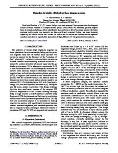
OPERATING PLASMA DENSITY ISSUES ON LARGE- . . . multistage accelerators there are additional effects to be considered [23], such as injection jitters and/or beam focusing errors between two subsequent stages. The results of our numerical calculations are shown in Fig. 1 together with the analytical estimates for h�i and �� =h�i, calculated from Eqs. (26) and (27). The numerical calculations are in good agreement with the analytical expressions. The relative energy spread in the beginning decreases approximately linearly in time due to the linear increase of the zeroth order mean energy. Later on, for t2 > �2�0 =ðh�i20 �� 2� Þ, it increases again due to radiative effects. For the numerical calculations the final value is ð�� =h�iÞnumerical ¼ 3:2 � 10�3 at the end of the stage,
Phys. Rev. ST Accel. Beams 14, 091301 (2011)
while the analytical estimate calculates ð�� =h�iÞanalytical ¼ 2:5 � 10�3 . The h�i increases almost linearly in time and reaches a final value of 1:0 � 106 for both the analytical and the numerical calculations after one stage, which corresponds to an electron energy of 500 GeV. Since our accelerator design aims to minimize radiative effects, the radiation damping occurs with a low damping rate �� � and the emittance decreases slowly. Starting from the initial value of "nx0 ¼ 2060 �m rad, emittance goes down to a final value of "nxf ¼ 2044 �m rad and, hence, is approximately conserved during one stage. We note that this behavior only holds true for a perfectly matched beam and that especially the emittance shows a different behavior in the beginning of the stage, when using a mismatched beam. IV. LUMINOSITY AND POWER REQUIREMENT The operational power is determined by the requirement for applications of the LPA linac. For the electron-positron linear collider, a critical requirement is the event rate that is determined by the product of collision cross section �ðe� eþ ! e� eþ Þ / E�2 b and luminosity L¼
fc Nb2 ; 4��x �y
(32)
where fc is the collision frequency, Nb is the number of particles per bunch, and �x and �y are the horizontal and vertical rms beam sizes at the interaction point (IP), respectively. The luminosity requirement for TeV future colliders is approximately scaled as L½1034 cm�2 s�1 � � 4ðEb ½TeV�Þ2 [21]. The required collision frequency is obtained as �2 � ��2 � �x �y Eb Nb fc ’ 5 ½kHz� ; (33) ð1 ½nm�Þ2 1 ½TeV� 109 and the beam power is given by
�3 � ��1 � �x �y Eb Nb : Pb ¼ fc Nb Eb � 0:8½MW� 2 1 ½TeV� ð1½nm�Þ 109 (34)
The number of particles per bunch is Nb ¼ FIG. 1. The beam dynamics over one stage for the ne ¼ 1015 cm�3 case in Table I: (a) mean energy, (b) relative energy spread, and (c) normalized transverse emittance for an initially matched beam with an initial emittance of 2060 �m rad injected into a 333 m long, low density LPA stage (ne ¼ 1015 cm�3 ) with initial energy 1 GeV, initial energy spread of 1%, and constant acceleration Ez ¼ 1:5 GV=m. The blue curves represent our numerical calculations, while the red dashed curves correspond to the respective analytical expressions, Eqs. (26) and (27). The maximum propagation distance h!� i0 tmax corresponds to the stage length.
Qb �l � 1:49 � 109 ðk � Þ2 e 1 � �l p x0 � ��1=2 Ez ne � ; E0 1017 ½cm�3 �
(35)
with hr2b i ¼ 2�2x0 . Thus, the required beam power is calculated as � ��1 �x �y 1 � �l E ðkp �x0 Þ�2 z � Pb � 0:54 ½MW� �l E0 ð1 ½nm�Þ2 � �1=2 �3 � Eb ne � : (36) 17 1 ½TeV� 10 ½cm�3 �
091301-7
KAZUHISA NAKAJIMA et al.
Phys. Rev. ST Accel. Beams 14, 091301 (2011)
The average laser power per stage is Pavg ¼ fc UL and the total wall-plug power for the collider is Pwall ¼ 2Nstage Pavg =�L ¼ 2fc UL Nstage =�L , where �L is the efficiency from wall plug to laser. Using Eqs. (8), (13), (33), and (35), the average laser power per stage is � � � � 1 � �l 2 ðkp rL Þ2 Ez �2 Pavg � 1:28 ½kW�a20 kp �z �l ðkp �x0 Þ4 E0 ��2 �2 � � �x �y �0 Eb � 1 ½�m� ð1 ½nm�Þ2 1 ½TeV� � ��1=2 ne � ; (37) 1017 ½cm�3 � and the wall-plug power yields � � � � a2 kp �z 1 � �l 2 ðkp rL Þ2 Ez �3 Pwall � 0:28 ½MW� 0 �L �l ðkp �x0 Þ4 E0 � �1=2 �3 � �x �y Eb ne � : (38) ð1 ½nm�Þ2 1 ½TeV� 1017 ½cm�3 � , Assuming the matched beam radius scales as �x0 / n�1=2 e �1=2 the number of particles per bunch scales as Nb / ne and the average laser power per stage scales as Pavg / n�1=2 . e 1=2 As a result, the wall-plug power scales as Pwall / ne . The overall efficiency from wall plug to beam is given by � �� � kp �x0 2 Ez 2 2Pb 3:9� �l �overall ¼ � 2 L : (39) Pwall a0 kp �z 1 � �l kp rL E0 For a 2 TeV center-of-mass energy collider with the luminosity L ¼ 4 � 1034 cm�2 s�1 , the frequency and power requirements are listed in Table I, assuming �x �y ’ 10 nm2 at the collision point and �L � 30%. The overall efficiency from wall plug to beam is a constant value 1.6% at various plasma densities for the underlying conditions. Hence, under constraint on the operational cost of the future linear colliders that limit the wall-plug power to a few 100 MW, the low operating plasma density in the range of 1015 –1016 cm�3 works in favor of the multi-TeV linear collider. V. SCALED PARTICLE-IN-CELL SIMULATIONS OF THE LPA STAGE In order to confirm scalability of the analytical expression on the wakefield excited by a Gaussian laser pulse in the quasilinear regime, we carried out two dimensional particlein-cell simulations [30] at the plasma densities 1018 , 2:3 � 1018 , 5 � 1018 , 7:5 � 1018 , and 1019 cm�3 . The computational window of dimension 120 � 120 �m2 moves at the speed of light. The number of grid points is 4000 � 200. The resolution in the laser propagation direction z is k0 �z ¼ 0:19. We use nine electrons per cell and a smooth neutralizing immobile ion background. We assume a preformed fully ionized plasma with parabolic plasma density profile of which the channel depth at r ¼ rL is set to the matched
condition �nc =ne ¼ 4=9. A diffraction limited, linearly polarized laser pulse is focused at the plasma channel entrance with a spot radius kp rL ¼ 3 and a temporal profile of the form a0 sin2 ð�t=2�L Þ expð�r2 =r2L Þ, where !p �L ¼ pffiffiffiffiffiffiffi 2 ln2kp �z ’ 1:7 is the FWHM pulse length. The laser is Gaussian in the transverse pffiffiffi direction with the normalized vector potential a0 ¼ 2. In these simulations no electrons are self-trapped and no significant diffraction of the laser pulse is observed through the single stage kp Lstage � ð�=2Þðnc =ne Þ. Hence, no beam loading effect is included in the simulations. In Fig. 2(a), we compare the maximum amplitude of the accelerating wakefield Ez and pffiffiffi the transverse electric field 2 Er ¼ ðK=kp Þ kp rE0 ’ Ez =ð 2kp rL Þ on the laser propagation axis y ¼ 0 with the analytical expression, Eqs. (1) and (15), respectively. Without beam loading, the analytical estimates of both the accelerating field and the focusing constant are in good agreement with the 2D PIC simulations. As a result, it is indicated that the accelerating field is approximately calculated as EM =E0 � 0:35a20 � 0:7 and scales as EM / n1=2 e as given by Eq. (2), while the focusing constant is calculated as K2 =k2p � 0:11 and scales as K 2 / ne . Figure 2(b) shows the evolution of the normalized laser field a=a0 at y ¼ 0 is shown as a function of k3p z=k20 ¼ kp zðne =nc Þ for various axial plasma densities, where k0 ¼ 2�=�0 is the laser wave number. The laser pulse undergoes self-focusing at the entrance of the plasma channel and propagates over the stage length kp Lstage � ð�=2Þðnc =ne Þ, keeping the amplitude a0 approximately constant as
FIG. 2. Results of scaled simulation: (a) scaling of the peak accelerating electric field Ez and the transverse electric field Er for various plasma densities. The normalized laser vector potential initially has a Gaussian form inpthe ffiffiffi transverse direction and a sin2 temporal profile with a0 ¼ 2, kp rL ¼ 3, and !p �L ¼ 1:7. The laser pulse propagates in a matched parabolic density channel with the channel depth at rL are �nc =ne ¼ 0:44. The solid lines show scaling calculated by Eq. (2) for the peak accelerating field pffiffiffi Ez and the average transverse electric field Er ’ Ez =3 2 given by Eq. (15). (b) Evolution of the laser field a in terms of the initial laser field a0 as a function of the propagation distance k3p z=k20 ¼ kp zðne =nc Þ at various plasma densities. The stage length corresponds to k3p Lstage =k20 ¼ �=2 and the effective dephasing length corresponds to k3p Ldp =k20 ¼ �.
091301-8
OPERATING PLASMA DENSITY ISSUES ON LARGE- . . . a=a0 � 1. After kp zðne =nc Þ � �=2, the laser field monotonically decreases, indicating the energy depletion. This implies that the wakefield has a constant amplitude . The over the stage length, which scales as Lstage / n�3=2 e typical longitudinal and transverse wakefield, Ez =E0 and Er =E0 , are shown at the plasma density 1018 cm�3 in Figs. 3(a)–3(d), respectively. As shown in Fig. 3, the acceleration-deceleration and focusing-defocusing regions are nearly symmetric, as suggested by the fact that the wakefield in the quasilinear regime is approximately in a sinusoidal form, which is in favor of accelerating and focusing both electron and positron beams. In addition, the plasma channel forms curvature of the plasma wave and a phase shift between the accelerating and focusing phase regions. With the beam loading, an electron beam accelerated in the plasma generates its own wake that damps the wakefield excited by the leading laser pulse. As expected from �1=2 with Eq. (3), the loaded charge scales as Qb / E�1 z / ne a constant beam loading efficiency. For a short bunch (kp �bz < 1) in the linear regime (Ez =E0 < 1), the scaling of the electron bunch charge was verified for both 2D and 3D simulations at ne ¼ 1018 and 1019 cm�3 [31]. We carried out the 2D PIC simulation [32] on acceleration of an electron bunch with the beam energy 1 GeV, the energy spread 1% (FWHM), and the number of electrons Nb ¼ 8:8 � 107 externally injected into a laser wakefield driven by a0 ¼ 1:4 at ne ¼ 7:5 � 1018 cm�3 . The dimensions of the laser pulse and the electron bunch are kept constant with respect to the plasma wavelength �p ¼ 12 �m, i.e. rL ¼ 3=kp ¼ 5:8 �m, �L ¼ 11 fs, �x0 ¼ 1=kp ¼ 1:9 �m, and �bz ¼ 0:047 �m, respectively. For this 10
p
k y
0
0.5 0
−5
−0.5
−10 −20 −15 −10 −5
(b)
0.5 Ez/E0
(a)
5
0
0
−20 −15 −10 −5
0.5
0.5
(c)
(d) 0
Er/E0
kpy
VI. DISCUSSIONS AND CONCLUSIONS
p
0
0
−5 −10 −20 −15 −10 −5 kp(z−ct)
0
−0.5
simulation, we use the simulation box size 30 � 60 �m2 , the number of simulation cells 3000 � 300, ten particles per cell for plasma and 1000 particles per cell for electron beam. When injecting the bunch into the peak accelerating field, an estimate of the energy gain over the stage length Lstage ¼ 0:5 mm yields the mean energy gain 63 MeV, while the simulation results in the mean energy 56 MeV, the relative energy spread 1.2% (FWHM), which show in good agreement and no significant degradation of the relative energy spread as shown in Fig. 4(a). Figure 4(b) shows the transverse phase space plot ðx; px =pz Þ at the mean beam energy 1.056 GeV, where x is the transverse position of particle, px and pz are the transverse and longitudinal momentum of particle, respectively. According to Eq. (19), the matched normalized emittance is estimated to be "n match � 24 �m rad, while the simulation results in "n sim � 79 �m rad, which indicates significant growth of the normalized emittance. However, it seems that a core part of bunched electrons is contained within the initial matched phase space area over the LPA stage, though particle behavior becomes fairly nonlinear and the emittance growth occurs in a complex manner.
0
k (z−ct)
p
5
FIG. 4. 2D PIC scaled simulation results of an electron bunch acceleration for a0 ¼ 1:4, rL ¼ 5 �m, �L ¼ 9 fs, and Nb ¼ 8:8 � 107 at the plasma density ne ¼ 7:5 � 1018 cm�3 ; (a) the electron energy spectrum and (b) the transverse phase space plot ðx; px =pz Þ. The red curve shows the initial energy spectrum and the red dots plot the initial transverse phase space distribution.
−0.5
k (z−ct) 10
Phys. Rev. ST Accel. Beams 14, 091301 (2011)
−0.5 −10
−5
0
5
10
kpy
FIG. 3. Laser wakefields in the quasilinear regime: (a) longitudinal electric field Ez ðkp y; kp Þ=E0 , (b) its on-axis distribution Ez ð0; kp Þ=E0 , (c) transverse electric field Er ðkp y; kp Þ=E0 , and (d) its transverse distribution Er ðkp y; �2:5Þ=E0 at the plasma density ne ¼ 1018 cm�3 , where ¼ z � ct is the coordinate moving with the laser pulse from the left to the right.
We have considered the design issues for laser-plasma accelerators based on the quasilinear laser wakefield regime and the design examples of a LPA-based electron/positron linac for 1 TeV beam energy, operated at the plasma density of 1015 , 1016 , 2:3 � 1016 , 1017 , and 1018 cm�3 , where the accelerating field is obtained as 1.5, 4.7, 7.2, 15, and 47 GV=m, respectively, for the fixed laser intensity a0 ’ 1:4 and the beam loading efficiency �l � 50%. Setting the stage length equal to the effective dephasing length Lstage ’ ð�p =4Þðnc =ne Þ leads the energy gain per stage to be 500, 45, 19, 4.5, and 0.47 GeV for five cases. The total linac length can be minimized by choosing the coupling distance to be equal to a half of the effective dephasing length Lcoupl ’ ð�p =8Þðnc =ne Þ that leads the total staging length to be 1:5Lstage . The higher operating density gives the shorter
091301-9
KAZUHISA NAKAJIMA et al.
Phys. Rev. ST Accel. Beams 14, 091301 (2011)
linac length as shown in Table I. However, a mm-scale coupling distance would provide no practical space for installing both laser and beam focusing systems at the operating density ne ¼ 1018 cm�3 . A practical coupling distance is determined by the beam focusing system that injects a beam with a spot size matched to the plasma wave. As shown in Fig. 5(a), designing the focusing system for a round beam may employ a quadrupole triplet system with the optimum configuration consisting of triplet lens with the focal length þ2fq , �fq , þfq spaced in the drift length fq that provides the shortest focal length fq ¼ 1=Kq lq for a focusing thin lens with the focusing strength Kq ½m�2 � ’ 0:3G ½T=m�=Ei ½GeV� and the length lq , where G ¼ @Br =@r is the magnetic field gradient and Ei is the injection beam energy into the LPA stage. For the beam transport and matching between consecutive stages, using two asymmetric triplet lens leads to the minimum coupling distance Lcoupl � 8fq . In order to shorten the focal length, one may employ the permanentmagnet-based quadrupoles [33] or the superconducting quadrupoles with the field gradient of the order of �103 T=m, which gives the triplet focal length fq � 1 m and the coupling distance Lcoupl � 10 m at the final beam energy 1 TeV. Employing the magnet-based focusing system leads the minimum linac length to be Ltotal � 433 m at the operating density 1016 cm�3 . The coupling distance of the order of �10 m may allow a direct optical coupling for the laser pulse injection by means of conventional laser optics with a large F number.
FIG. 5. Schematic illustrations of multistaged laser-plasma accelerators composed of the LPA stages and the coupling section made of the conventional technologies (a) and the plasma-based technologies (b). For example, the conventional coupling uses an off-axis parabolic mirror for laser focusing and two triplet lenses for beam focusing, while the plasma-based coupling uses a curved plasma channel for the laser off-axis injection and a plasma lens for the beam injection to the next LPA stage.
The coupling distance of the order of tens cm may be achieved by means of a self-focusing plasma lens where the plasma electrons move to neutralize the beam charge, leaving the beam-current self-pinching forces unbalanced [34]. The radial self-pinching forces inside the beam with bi-Gaussian beam-density profile b ¼nb expð�r2 =2�2br Þ� expð�z2 =2�2bz Þ is Fr ¼ 4�me c2 re nb
�2br 2 2 2 2 ½1 � e�ðr =2�br Þ �e�ðz =2�bz Þ ; (40) r
where nb ¼ Nb =ð2�Þ3=2 =ð�2br �bz Þ is the beam density of the bunch with the number of particles Nb , the rms radius �br , and the rms length �bz . Defining the radial focusing strength as KS ¼ Fr =ðr�me c2 Þ, averaging focusing strength over the bunch length gives rN hKS i ’ pffiffiffiffi e 2 b ; 2 ��br �bz �
(41)
in the core of the beam for r2 2�2br . For a thin plasmalens focus system, the focal length of the plasma lens will be pffiffiffiffi � � 1 2 ��2br �bz � 1 ½cm� f¼ ¼ � 25 ½cm� ; (42) hKS ilp re Nb lp lp with the typical beam parameters concerned here, Nb � 108 , �br � 10 �m, �bz � 1 �m, and � � 2 � 106 , where lp is the length of the plasma lens. The plasma density in the lens is set to be nel > nb � 1017 cm�3 . The plasma focusing of both electron and positron beams has been successfully demonstrated with a short plasma target [35]. Employing the plasma lens for the beam focusing system with required coupling distance Lcoupl � 1 m leads to the minimum linac length to be Ltotal � 190 m at the operating density ne ¼ 2:3 � 1016 cm�3 . In order to focus intense laser pulses into the subsequent LPA stage in the optimum coupling distance of the order of 0.1 m, plasma mirrors are suggested as a promising technology [36]. Alternatively, in such a short coupling distance, a curved plasma waveguide with a parabolic density channel profile will be used to propagate intense laser pulses into the LPA stage from the off-axis focus point as shown in Fig. 5(b). Since a radial equilibrium position shifts in the curved plasma waveguide, the minimum acceptable radius of channel curvature is given by Rcurv
ðnc =�nÞrch , where the density profile nðrÞ ¼ n0 þ �nr2 =r2ch is assumed. For �n � 1017 cm�3 and rch � 0:2 mm, the radius of curvature becomes Rcurv � 2 m and the off-axis distance � � 1 mm with respect to the accelerator beam axis requires the channel length lch � pffiffiffiffiffiffiffiffiffiffiffiffiffiffiffiffi 2�Rcurv � 6 cm. The curved plasma channel experiment with 10 cm radius of curvature showed as high as 85% transmission of 50 �m spot radius for the laser intensity 1016 W=cm2 [37]. Schematics of the coupling schemes
091301-10
OPERATING PLASMA DENSITY ISSUES ON LARGE- . . . relying on the conventional and the plasma-based technology are illustrated with Fig. 5. In the quasilinear regime, both longitudinal and transverse wakefields can be scaled with the operating plasma density as indicated by the PIC simulation results, which are carried out under the similarity of the laser pulse dimensions kp �z and kp rL for fixed a0 propagating the matched plasma channel. Since the single-stage length is limited to a half the effective dephasing length Ldp ’ ð�p =2Þðnc =ne Þ where the electrons undergo both focusing and acceleration, the laser intensity remains approximately constant over a whole stage before followed by its significant decrease. The scaled acceleration simulations show that the expected energy gain can be obtained for the scaled parameters of laser and electron beams. Furthermore, no significant degradation of the energy spread and the transverse normalized emittance is observed in a core part of bunched electrons over the LPA stage. This result confirms that the stage length over dephasing �=4 is optimized for keeping the energy gain and the beam qualities, of which deterioration emerges after the designed stage via a highly nonlinear coupled process in the longitudinal and transverse phase space of wakefields. Once the relevant normalized laser parameters are set to be constant, most of the parameters related to beam dynamics are also scaled with the plasma density ne on the assumption that the laser spot radius kp rL , the accelerating gradient Ez =E0 , and the initial beam radius kp �x0 are constant. For high-energy applications of LPAs, the performance is mostly limited by the beam qualities such as the energy spread and the emittance as well as the beam energy and charge. As a consequence of the PanofskiWenzel theorem [38] on the relation between longitudinal and transverse wakefields in the linear regime, @Ez =@r ¼ @Er =@z, electrons accelerated in the wakefield undergo the radial focusing force simultaneously and off-axis electrons exhibit the betatron oscillation that emits radiation when traveling in a focusing channel. As a result of the betatron radiation, an energy loss and an increase of the relative energy spread are induced while the normalized emittance decreases due to radiation damping if the matched beam is injected into the LPA stages. Taking account of synchrotron radiation, of which the radiated power increases as �2 , high-energy LPAs in the high-density operation will be confronted with significant radiative energy loss and energy-spread increase as shown in Table I. If we set the tolerable relative energy spread to be less than 1%, the low density operation at ne � 1015 cm�3 may be the only allowable choice. On the contrary, the transverse emittance corresponding to the matched beam radius increases as at the initial acceleration stage, but "nmatch / �p / n�1=2 e eventually decreases due to radiative damping of the betatron oscillation without mismatching with the plasma focusing channel, injection errors, and other imperfections of the LPA stage.
Phys. Rev. ST Accel. Beams 14, 091301 (2011)
For the collider application, requirements of the collision frequency, the beam power, and the wall-plug power are estimated on a priori assumptions of the luminosity, the colliding beam optics, and the laser efficiency. Table I summarizes the underlying parameters of design examples for a 2 TeV center-of-mass energy collider operated at the plasma density range for 1015 –1018 cm�3 . Many of the underlying parameters for the LPA design scale with the operating plasma density. For reference, the scaling dependence of the important parameters on the plasma density is summarized in Table II. Inspecting Table I, if the eventual collider design will be dominated by the operational cost that limits the wall-plug power of the laser driver, which scales as Pwall / ne1=2 , i.e., the required wall-plug power at ne ¼ 1015 cm�3 is an order of magnitude smaller than at ne ¼ 1017 cm�3 . Hence, such low density operation is the way to go for the reality of future linear colliders. In addition, the lower the plasma density is, the larger the tolerance of beam handling is and the superior the beam qualities are. This results from a larger phase volume of the accelerating bucket and less energy loss produced by the betatron radiation, which is an unavoidable effect in laser-plasma accelerators. A drawback is a large laser energy per stage, which scales as UL / n�3=2 and leads to be roughly a 10 kJ e pulse with a nearly 1 ps duration for the 1015 cm�3 case. However, there is an ongoing effort for realizing the pulsed 10–100 kJ laser systems [39]. Such a laser will herald the research as we have described here. Finally, although requiring very high-average laser power of MW class for all cases may look daunting, rapid technological developments will be anticipated on this issue, for an example, as launched by the coherent amplification network [40].
TABLE II. Scaling dependence of LPA parameters on the operating plasma density. Accelerating field Ez Focusing constant K Stage length Lstage Energy gain per stage Wstage Number of stages Nstage Total linac length Ltotal Number of particles per bunch Nb Laser pulse duration �L Laser peak power PL Laser energy per stage UL Radiation loss �� Radiative energy spread �� =�f Initial normalized emittance "n0 Collision frequency fc Beam power Pb Average laser power Pavg Wall-plug power Pwall
091301-11
/ n1=2 e / n1=2 e / n�3=2 e / n�1 e / ne / n�1=2 e / n�1=2 e / n�1=2 e / n�1 e / n�3=2 e / n1=2 e / n1=2 e / n�1=2 e / ne / n1=2 e / n�1=2 e / n1=2 e
KAZUHISA NAKAJIMA et al.
Phys. Rev. ST Accel. Beams 14, 091301 (2011)
ACKNOWLEDGMENTS The authors would like to thank G. Mourou, W. Leemans, M. Semekh, C. Barty, W. Sandner, and C. Labaune. The work has been supported by the National Natural Science Foundation of China (Projects No. 10834008 and No. 60921004) and the 973 Program (Project No. 2011CB808104). K. Nakajima is supported by Chinese Academy of Sciences Visiting Professorship for Senior International Scientists. A portion of this work was carried out as part of the LMU graduate course term project (‘‘Laser Acceleration and High Field Science’’, Summer 2011, Munich). The work has been supported by MAP.
[1] T. Tajima and J. M. Dawson, Phys. Rev. Lett. 43, 267 (1979). [2] B. Brozek-Pluskab et al., Radiat. Phys. Chem. 72, 149 (2005); R. Crowell et al., Radiat. Phys. Chem. 70, 501 (2004). [3] T. van Outheusden et al., Phys. Rev. Lett. 105, 264801 (2010). [4] A. Giulietti et al., Phys. Rev. Lett. 101, 105002 (2008). [5] H. Hamster et al., Phys. Rev. Lett. 71, 2725 (1993); W. Leemans et al., Phys. Rev. Lett. 91, 074802 (2003). [6] S. Kneip et al., Nature Phys. 6, 980 (2010); M. Kando et al., Phys. Rev. Lett. 99, 135001 (2007). [7] K. Nakajima et al., Phys. Rev. Lett. 74, 4428 (1995); A. Modena et al., Nature (London) 377, 606 (1995). [8] W. P. Leemans et al., Nature Phys. 2, 696 (2006). [9] C. E. Clayton et al., Phys. Rev. Lett. 105, 105003 (2010). [10] T. Kameshima et al., Appl. Phys. Express 1, 066001 (2008). [11] S. Karsh et al., New J. Phys. 9, 415 (2007). [12] O. Lundh et al., Nature Phys. 7, 219 (2011). [13] J. Osterhoff et al., Phys. Rev. Lett. 101, 085002 (2008); N. A. M. Hafz et al., Nat. Photon. 2, 571 (2008). [14] S. P. D. Mangles et al., Nature (London) 431, 535 (2004); C. G. R. Geddess et al., Nature (London) 431, 538 (2004); J. Faure et al., Nature (London) 431, 541 (2004). [15] I. Kostyukov, A. Pukov, and S. Kiselev, Phys. Plasmas 11, 5256 (2004); W. Lu, C. Huang, and M. Zhou, Phys. Rev. Lett. 96, 165002 (2006). [16] D. H. Froula et al., Phys. Rev. Lett. 103, 215006 (2009).
[17] J. Faure et al., Nature (London) 444, 737 (2006); H. Kotaki et al., Phys. Rev. Lett. 103, 194803 (2009). [18] K. Schmid et al., Phys. Rev. ST Accel. Beams 13, 093101 (2010). [19] A. Pak et al., Phys. Rev. Lett. 104, 025003 (2010); C. McGuffey et al., Phys. Rev. Lett. 104, 025004 (2010). [20] J. S. Liu et al., Phys. Rev. Lett. 107, 035001 (2011). [21] C. B. Schroeder et al., Phys. Rev. ST Accel. Beams 13, 101301 (2010). [22] M. Xie, T. Tajima, K. Yokoya, and S. Chattopadyay, AIP Conf. Proc. 398, 233 (1997). [23] S. Cheshkov, T. Tajima, W. Horton, and K. Yokoya, Phys. Rev. ST Accel. Beams 3, 071301 (2000); C Chiu, S. Cheshkov, and T. Tajima, Phys. Rev. ST Accel. Beams 3, 101301 (2000). [24] P. Michel, C. B. Schroeder, B. A. Shadwick, E. Esarey, and W. P. Leemans, Phys. Rev. E 74, 026501 (2006). [25] B. A. Shadwick, C. B. Shcroeder, and E. Esarey, Phys. Plasmas 16, 056704 (2009). [26] S. F. Martins, R. A. Fonseca, W. Lu, W. B. Mori, and L. O. Silva, Nature Phys. 6, 311 (2010). [27] W. Lu et al., Phys. Rev. ST Accel. Beams 10, 061301 (2007). [28] P. Sprangle and E. Esarey, Phys. Fluids B 4, 2241 (1992). [29] J. D. Jackson, Classical Electrodynamics (Wiley, New York, 1999), 3rd ed. [30] H. Xu et al., Chin. J. Comput. Phys. 20, 326 (2003). [31] E. C. Michel et al., in Advanced Accelerator Concepts: 13th Workshop, edited by C. B. Schroeder, W. Leemans, and E. Esarey (AIP, New York, 2009), Vol. 1086, pp. 297–302. [32] C. Nieter and J. R. Cary, J. Comput. Phys. 196, 448 (2004). [33] J. K. Lim et al., Phys. Rev. ST Accel. Beams 8, 072401 (2005). [34] J. R. Rosenzweig and P. Chen, Phys. Rev. D 39, 2039 (1989). [35] H. Nakanishi et al., Phys. Rev. Lett. 66, 1870 (1991); J. S. Ng et al., Phys. Rev. Lett. 87, 244801 (2001). [36] D. Panasenko et al., J. Appl. Phys. 108, 044913 (2010). [37] Y. Ehrlich et al., Phys. Rev. Lett. 77, 4186 (1996). [38] P. Chen, Part. Accel. 20, 171 (1985). [39] T. Tajima and G. Mourou, Phys. Rev. ST Accel. Beams 5, 031301 (2002). [40] G. Moutou et al., AIP Conf. Proc. 827, 152 (2006).
091301-12