Open Access Journal
Journal of Power Technologies 93 (5) (2013) 383–394 journal homepage:papers.itc.pw.edu.pl
Operation of a conceptual A-USC power unit integrated with CO2 capture installation at part load K. Stepczy´ ˛ nska-Drygas∗ , K. Bochon, S. Dykas, H. Łukowicz, W. Wróblewski Institute of Power Engineering and Turbomachinery Silesian University of Technology, Gliwice, Poland
Abstract The key aims in research and development in the coal-fired power sector are improving the efficiency of electricity generation and reducing CO2 emissions. Modern power systems require power units to be able to work flexibly at part loads with high efficiency. This paper presents a conceptual 900 MW coal-fired power unit. The unit operates with advanced ultra-supercritical (A-USC) steam parameters 35 MPa/700◦ C and at 49% net efficiency. Improved efficiency results in significantly reduced CO2 emissions. Further emission reduction requires the integration of coal-fired power plants with CO2 capture installation. A newly-built power plant offers the possibility of fully optimized integration to reduce efficiency loss, which is related to the post-combustion capture process. CO2 capture by wet chemical absorption MEA can be characterized by three indicators: the demand for heat, electric power to drive auxiliary equipment and cooling. In order to calculate these indicators the capture process was modeled in Aspen Plus. Calculated indicators for nominal and part load operation were used to model an integrated power unit in Ebsilon Professional 10.0. The characteristics of operating a power unit integrated with CO2 capture installation were determined. Keywords: CCS, A-USC power plant 1. Introduction Improving the efficiency of coal-fired power units is essential in attempts to reduce the consumption of primary fuels and CO2 emissions. New advances in materials engineering have made the technology of super-critical power units more widespread. But there is a new generation of this technology—the advanced ultra-supercritical (A-USC) power plant— which offers exciting prospects. Alongside boosting electricity generation efficiency, carbon capture and geological storage (CCS) installations will have to ∗
Corresponding author Email address:
[email protected] (K. Stepczy´ ˛ nska-Drygas∗ )
be constructed to meet European Union targets on greenhouse gas emissions. Pursuant to the CCS Directive [1], each new power plant with a rated electrical output of 300 MW or more has to meet the ”capture ready” requirements: availability of suitable CO2 storage sites, technical and commercial feasibility of CO2 transport facilities, technical and commercial feasibility of retrofitting the new power unit with a CO2 capture installation. The present and future potential for achieving near-zero CO2 emissions in the combustion of organic fuels is most apparent in the implementation of CO2 capture after combustion—post-combustion technology. An extensive analysis of CO2 capture technologies in terms of their application for the
Journal of Power Technologies 93 (5) (2013) 383–394 high power units was presented in [2, 3]. In postcombustion processes CO2 is captured from the flue gas stream. Technologies aimed at CO2 separation from electricity generation processes should feature: (i) high separation selectivity between individual constituents of the treated gas (carbon dioxide— sulfur compounds), (ii) high effectiveness of the gas treatment process, and (iii) low operating costs. Moreover, energy losses should be as small as possible. The technology which has been used on an industrial scale for many years is based on chemical absorption. Other methods are tested and applied on a smaller technological scale. Absorption processes make it possible to obtain a high degree of purity of the separated product [4]. The chemical absorption process consists in letting flue gases pass through an absorption column where they come into contact with a liquid that absorbs CO2 . The most common chemical absorption technology is the process based on the aqueous solution of first-order amines. The one which is used most often is ethanolamine (or monoethanolamine— MEA). MEA is obtained through reacting ethylene oxide with ammonia. Its aqueous solution behaves like a weak base, which can neutralize acidic molecules such as CO2 . First-order amines have a fast reaction rate, but require a bigger amount of heat for regeneration compared to higher-order amines. Therefore, combining different amines to take advantage of their individual strong points is taken into consideration. Moreover, research is being carried out on new types of amines, including synthetic ones. CO2 capture requires the system to be supplied continuously with the heat needed to reverse the reaction. The temperature of the heating agent fed to the stripper depends on the sorbent. The aqueous solution of MEA has to be heated before the stripper to the temperature of 124◦ C. Using MEA technology, 2...5 MJ of heat per kg of separated CO2 has to be supplied for the desorption process, note that there are other technologies which give negative energy penalty values [5]. The heat for the regeneration process is usually supplied in the form of steam with appropriate parameters and is extracted from the power plant thermal cycle. In addition, the chemical absorption process involves satisfying the demand for
the extra electric power needed to drive the auxiliary equipment—pumps, fans and the CO2 compressor. This results in a drop of 9 to 13 percentage points in the net efficiency of electricity generation. There are many challenges related to integrating a coal-fired power plant with CO2 installation. Three basic conditions need to be satisfied for the integration of a CO2 capture and compression system with a power unit: • sufficient heat has to be supplied to the CO2 capture installation for the sorbent regeneration; this heat must feature appropriate parameters (pressure, temperature) which are constant throughout the entire range of the power unit load, • appropriate cooling has to be provided due to the considerable amount of waste heat from the CO2 capture and compression system, • power has to be supplied to drive the CO2 compressor and the auxiliary equipment of the CO2 capture installation (pumps, fans). The best solution to supply a large amount of heat to the capture installation is to extract steam from the main cycle of the coal-fired power unit. Due to the required parameters of steam and its considerable mass flow, the best place for extraction is the turbine IP/LP crossover pipe. An analysis of the possibilities of steam extraction from the condensing power unit for the CO2 capture installation was presented in [6, 7]. The extraction of a large amount of steam from the IP/LP crossover pipe affects the operating conditions of the LP turbine, especially at part load operation. The steam mass flow to the LP turbine decreases by half. Operation at partial load affects the parameters of the steam sent to the capture unit. In the case of new power plants, it is possible to optimize the power unit parameters and steam turbine configuration in terms of integration with a CO2 capture installation. This opens the way for new solutions to be used to minimize energy losses related to the processes of post-combustion capture. Preliminary analysis of integration of a power unit with capture installation was presented in [8].
— 384 —
Journal of Power Technologies 93 (5) (2013) 383–394 The Ebsilon Professional 10.0 software package was used in analysis of the operation of the power unit integrated with a CO2 capture installation at nominal and part load. The power unit was modeled in the program from the water-steam side and from the flue gas side. The CO2 capture and compression system was modeled as a ”black box”. For the ”black box”, the results obtained for the model of chemical absorption in the ASPEN Plus program became the input parameters. 2. Integration of a coal-fired power unit with CO2 capture installation 2.1. Integration of coal-fired power unit with CO2 capture installation Table 1: Basic parameters at individual points of the CO2 capture installation
Stream
Temperature, K
Pressure, kPa(a)
Mass flow, kg/s
G1 G2 G3 G4 G5 H2 O 1 Am 1 Am 2 Am 3 Am 4 Am 5 Am 6 Am 7 Makeup Am CO2 1 CO2 2 H2 O 2
321.0 328.9 313.2 340.3 323.2 323.2 321.0 321.1 390.8 398.5 331.1 313.2 313.5 315.2
101 108 107 105 105 105 105 220 220 210 210 210 105 110
769.9 769.9 769.9 703.7 641.5 62.2 2375.2 2375.2 2375.2 2226.5 2226.5 2226.5 2309.0 20.2
378.7 308.2 308.2
210 200 200
209.1 148.7 60.4
The CO2 capture installation was modeled in Aspen Plus. The diagram of the CO2 capture installation is shown in Fig. 1. After the process of deep desulfurization, flue gases (G) are pre-cooled
to the temperature of 40◦ C in the COOL1 direct contact cooler and then introduced into the ABS absorber column. In the fan (FAN), the flue gases are slightly compressed to the pressure of 108 kPa(a), which makes it possible to overcome flow resistance. A 30% MEA solution (Am7) is introduced in the upper part of the absorber (ABS), also with the temperature of 40◦ C. The flue gases are fed in the lower part of the ABS absorber. Flowing through the bottom of the column, the MEA solution absorbs CO2 from flue gases. Due to the heat released in the exothermic absorption reaction, the flue gas temperature rises to 67.1◦ C (Sp 4). Having gone through the absorber, the flue gases are directed to the water separator (SEP1), where they are cooled to the temperature of 50◦ C (which is the nominal temperature of flue gases introduced into a cooling tower). The water condensed during the cooling process is redirected to the capture installation (H2 O 1). Owing to the fact that part of the water contained in flue gases is recovered in SEP1, the losses in the cycle of the CO2 capture installation are reduced, but the amount of waste heat increases. The MEA solution (Am1), which is rich in CO2 , leaves the bottom of the ABS absorber and is heated in the CFHX cross-flow heat exchanger, where the heating agent is a lean amine solution (Am4) returning from the stripper column (STR). The preheated rich amine solution (Am3) is fed into the stripper (STR). The desorption process occurs at the temperature of 124◦ C. The heat supplied to the desorption column is generated in the reboiler (REB). As a result of the desorption process, the stream of CO2 and steam (CO2 1) leaves the stripper (STR) and is directed to the CO2 /H2 O separator (SEP2), where the gas is cooled to the temperature of 35◦ C and most of the steam gets condensed (H2 O 2). Next the stream of CO2 (CO2 2) is directed to an eight-stage compressor with inter-stage cooling. Basic parameters at individual points of the CO2 capture installation are listed in Table 1. The parameters of the CO2 capture installation are listed in Table2. A simulation of the CO2 separation process performed using the Aspen Plus program shows that the capture installation demand for heat is 516.3 MWt , i.e. 3.51 MJ/kgCO2 . The cooling demand ratio for the separation installation is 3.22 MJ/kgCO2 . In light of the cooling of the CO2 compressor, the
— 385 —
Journal of Power Technologies 93 (5) (2013) 383–394 Table 2: Basic parameters of the CO2 capture installation
Flue gas mass flow, kg/s CO2 mass flow in flue gases, kg/s Captured CO2 mass flow, kg/s CO2 mass flow in flue gases after capture, kg/s Capture degree Heat flux supplied to the installation, MWt Heat demand ratio for regeneration, MJ/kg CO2 CO2 /H2 O separator power, MWt Sorbent cooler power after cross-flow exchanger, MWt Flue gas cooler power before absorber, MWt Flue gas/H2 O separator power, MWt Total cooling power, MWt Cooling demand ratio, MJ/kg CO2 L/G ratio, kg sor./kg flue g. Lean solution loading, molCO2 /molMEA Rich solution loading, molCO2 /molMEA
770 163 147 16.4 90% 516 3.51 164 136 12.6 162 474 3.22 3.0 0.19 0.49
with a lower heating value of 23 MJ/kg (fuel composition in the working state: water=0.09, ash=0.2, carbon=0.6, hydrogen=0.038, oxygen=0.054, nitrogen=0.013, sulfur=0.01). The composition of wet flue gases was calculated assuming perfect and complete combustion (flue gas composition: CO2 =0.1416, SO2 =0.0009, O2 =0.0329, N2 =0.7378, H2 O=0.078, Ar=0.0088). The feed water temperature at the boiler inlet is 330◦ C. The calculations take account of the demand for electric power of the power unit basic own-needs equipment (the boiler feed pump, the condensate pumps, the cooling water pumps, the air and flue gas fans, and the coal pulverizers) as well as of the CO2 capture and compression installation (pumps, fans, CO2 compressor). All own-needs devices are driven electrically. Table 4: Basic indices of the operation of the reference 900 MW power unit and the power unit integrated with a CO2 capture installation
Ref- CCI erence Nominal IP/LP, MPa(a) Live steam mass flow, kg/s Steam mass flow to the CO2 capture installation, kg/s Heat flux given up in the main turbine condenser, MWt Waste heat flux from the CO2 capture and compression installation, MWt Heat flux given up in the cooling tower, MWt Cooling water mass flow, kg/s Gross electric power, MWe Gross efficiency, % Net electric power, MWe Net efficiency, %
ratio is 3.76 MJ/kgCO2 . 2.2. Structure and basic parameters of a coal-fired power unit with a CO2 capture installation Table 3: Basic parameters of the power unit
Live steam mass flow Live steam pressure/temperature Reheated steam pressure/temperature Feed water final temperature Pressure in the condenser
578.4kg/s 35MPa/700◦ C 7.5MPa/720◦ C 330◦ C 4.5kPa(a)
The subject of the analysis is a conceptual ultrasupercritical coal-fired power unit integrated with an installation of CO2 separation by means of chemical absorption using MEA as sorbent (Fig. 1). The live and reheated steam parameters are 35 MPa(a)/700◦ C and 7.5 MPa(a)/720◦ C, respectively. The basic parameters of the power unit are listed in Table 3. The power unit under analysis is fired with hard coal
0.5 0.5 578 578 0 201 742
363
0
552
771
944
20,50025,150 900 764 52.6 44.7 839 636 49.0 37.2
Table 4 presents basic indices of the operation of the reference power unit and the power unit integrated with a CO2 capture installation. The reference configuration of the advanced ultra-supercritical cycle which was assumed to analyze the impact of the power plant integration with a CO2 capture installation on the basic indices of the power unit operation
— 386 —
Journal of Power Technologies 93 (5) (2013) 383–394 was developed in previous analyzes described in [9– 11]. Assuming identical parameters and nominal boiler output of 578 kg/s, the power plant achieves net electric power of 839 MW and electricity generation efficiency of 49%. The integrated plant features net electric power of 650 MW and net electricity generation efficiency of 38%. Compared to the reference variant, the drop in power unit net efficiency was 11.8 percentage points. Assuming an identical mass flow of live steam, net electric power output of the power unit fell by approximately 200 MWe , 57 MWe of which is the compressor drive and about 6 MWe —the drive of the capture installation auxiliary equipment; the remaining loss results from extraction of steam for the capture installation. In the analysis of the coal-fired power unit cycle integration with the CO2 capture and compression system it is assumed that the power unit is adapted for continuous co-operation with the CO2 capture installation. The steam for the sorbent regeneration is extracted from the main turbine IP/LP crossover pipe. Due to the fact that more than half of the mass flow from the IP/LP crossover pipe is directed to the CO2 capture installation, the low-pressure part of the turbine LP is reduced to one double-flow part, compared to the reference system. The aim is to reduce the energy losses and operating problems resulting from the fact that the LP turbine would have to operate at very low loads. The temperature difference in the reboiler between the condensing steam fed from the power unit cycle and the heated MEA solution is assumed at the level of 10 K. Consequently, the required parameters of the steam feeding the reboiler are as follows: 0.3 MPa(a) and 134◦ C. These steam parameters are constant throughout the entire range of load. The entire heat flux supplied to the desorption column in the reboiler, reduced by the energy needed for the CO2 and sorbent separation, must be collected at other places of the capture installation: in the flue gas cooler before the absorber, in the cooler in the absorber wash section, in the sorbent cooler, in the condenser at the stripper outlet. A considerable heat flux must also be carried away from the interstage coolers of the CO2 compressor. The entire heat flux that must be carried away from the CO2 separation and compression installation for the power unit under
consideration totals 552 MWt . Therefore, retrofitting the power unit with a CO2 capture installation results in a significant increase in the amount of heat that has to be carried away in the cooling tower—by about 21% (from 771 MWt in the reference power unit to 944 MWt for the unit with a separation installation). In the power unit cycle with a CO2 capture installation 37.5% of waste heat comes from steam condensation in the steam turbine condenser. This is caused by the fact that less than half of the steam mass flow leaving the turbine IP part is expanded in the LP part. It is assumed in the analysis that the CO2 separation and compression installation is cooled with cooling water with the temperature of 19.1◦ C. The increment in the cooling water temperature is the same as for the turbine condenser: 9 K. The mass flow of the water cooling the power unit with the CO2 separation installation is increased appropriately to maintain the pressure in the turbine condenser at the same level as in the reference power unit: 0.0045 MPa(a). After the capture process the (moist) CO2 mass flow is directed to the compressor. The compressor is composed of 8 stage groups. Between individual stage groups CO2 is water-cooled to the temperature of 35◦ C and compressed to the pressure of 15.3 MPa(a). The compressor electric power is 57 MWe , and the heat flux that must be collected from interstage coolers totals 79 MWt . 2.3. Adjustment of design pressure in the IP/LP crossover pipe For maximum efficiency of the power unit in its nominal point of operation, the design pressure in the turbine IP/LP crossover pipe should be selected at a level that matches the value required by the CO2 capture installations (for the case under analysis the pressure value is assumed at 0.304 MPa(a)+8% loss=0.328 MPa(a)). Additionally, the pressure of the steam fed into the reboiler must be kept constant in the entire range of the power unit load. For this reason, it is necessary to adjust the steam mass flow directed to the CO2 separation installation. Throttling the steam flowing to the turbine LP part during the power unit operation under a partial load has an adverse impact on the electricity generation efficiency. Another solution is to select an appropriately lower value of the design pressure in the IP/LP
— 387 —
Journal of Power Technologies 93 (5) (2013) 383–394 crossover pipe, which will ensure proper parameters of the steam fed into the separation installation even at the power unit minimum load without having to throttle the steam flow directed to the turbine LP part. This will make it possible to improve the power unit efficiency under a partial load. However, at the power unit rated load the pressure value in the turbine IP/LP crossover pipe exceeds the value required by the CO2 capture installation. Due to that, it is necessary to throttle the steam flow directed to the separation installation, which causes energy losses and reduces power unit efficiency under the rated load. It may turn out that the best answer to the problem is to combine both solutions and select a nominal pressure value in the turbine IP/LP crossover pipe that will ensure the best indices of the power unit operation in the entire scheduled load range. Fig. 3 presents the impact of the design pressure in the turbine IP/LP crossover pipe on power unit efficiency and net electric power under the rated load. A reduction in the nominal pressure value in the crossover pipe from 0.5 MPa to 0.33 MPa results in an increase in power unit net efficiency by about 0.81 percentage points (the lower the pressure, the lower the energy loss caused by throttling the steam flow directed to the CO2 capture installation). However, a reduction in the nominal pressure value also results in a decrease in the efficiency of the power unit operating under a partial load (lower nominal pressure makes it necessary to throttle the steam flow to the turbine LP part). Moreover, pressure reduction in the crossover pipe involves an increase in the steam mass flow directed to the CO2 capture installation by 3.9% and a decrease in the mass flow of the water cooling the entire power unit by 1.5%. 3. Operation under partial load 3.1. Carbon capture installation—operation under partial load A simulation of the CO2 separation installation operation under a partial load in the range of 0.8...1.05 of the nominal value of the live steam mass flow was carried out. The analysis of operation of the capture installation at partial load was limited to the range of 0.8...1.05, due to the fact that the installation will
Figure 3: Impact of design pressure in the turbine IP/LP crossover pipe on the power unit efficiency and net electric power under rated load
Figure 4: Captured CO2 mass flow depending on the power unit load
consist of a number of the absorber-stripper units operated in parallel. The calculations were performed keeping a constant mass flow of the sorbent solution. The amount of heat supplied for regeneration was varied so that CO2 capture could be maintained at the level of 90%. Fig. 4 presents the curve illustrating changes in the amount of captured CO2 depending on the power unit load. It can be seen in it that the percentage change in the power unit load corresponds to a similar range of changes in the amount of captured
— 388 —
Journal of Power Technologies 93 (5) (2013) 383–394
Figure 5: The CCI heat demand depending on the power unit load
Figure 7: The CCI cooling power depending on the power unit load
Figure 8: The CCI cooling demand ratio (MJ/kg CO2 ) depending on the power unit load Figure 6: The CCI heat demand ratio (MJ/kgCO2 ) depending on the power unit load
CO2 . Fig. 5 presents the capture installation heat demand depending on the power unit load and Fig. 6 presents the heat demand ratio (MJ/kgCO2 ). The heat flux for the sorbent regeneration falls as the load increases, which results directly from the smaller mass flows of flue gases and captured CO2 . It can be seen clearly that the heat demand ratio (MJ/kgCO2 ) is at its lowest for the nominal load. If the load value exceeds 100%, the ratio value rises more abruptly than for partial load. Fig. 7 presents the capture instal-
lation cooling power depending on the power unit load and Fig. 8 presents the cooling demand ratio. The CO2 separation installation cooling demand ratio (MJ/kgCO2 ) assumes the lowest value for the nominal load. 3.2. Integrated power unit—operation under partial load It is assumed that the coal-fired power unit operates with sliding pressure in the entire load range. The Stodola equation and typical characteristic curves illustrating the machinery and equipment
— 389 —
Journal of Power Technologies 93 (5) (2013) 383–394 operation were assumed to analyze the power unit performance under a partial load.
Figure 9: Characteristics of unit gross and net power on the power unit load
Figure 10: Characteristics of unit net efficiency on the power unit load for different values of design pressure in the turbine IP/LP crossover pipe
Figure 11: Changes in power unit net electricity generation efficiency depending on the power unit load for different values of design pressure in the turbine IP/LP crossover pipe (ref - reference power unit with no CO2 capture installation)
The operation of the power unit integrated with a CO2 separation installation was analyzed in the load range of 0.8...1.05 of the nominal mass flow of live steam. A comparison of the characteristics of the electric power of the reference unit and integrated unit is presented on Fig. 9. The changes in gross and net power with changing load are linear for both cases. Fig. 10 presents the characteristic of net efficiency of the integrated power unit for different values of design pressure in the turbine IP/LP crossover pipe. The highest net efficiency for nominal power unit load was achieved for the lowest crossover pressure. However, the characteristics of the lowest crossover pressure are the steepest. Fig. 11 presents changes in power unit net efficiency depending on the live steam mass flow for different values of design pressure in the crossover pipe, compared to the reference power unit with no CO2 capture installation. For lower values of design pressure in the crossover pipe (0.33 and 0.35 MPa(a)) the decrease in power unit efficiency is distinctly bigger. This results from the fact that under a lower load of
— 390 —
Journal of Power Technologies 93 (5) (2013) 383–394 the power unit the flow to the turbine LP part must be throttled to maintain constant parameters of steam directed to the CO2 capture installation. However, the higher the design pressure in the IP/LP crossover pipe, the lower the efficiency of the power unit operating under the nominal load, which is caused by the need to reduce the pressure of steam directed to the capture installation. 4. Conclusion The coal-fired power unit with a CO2 capture and compression installation, compared to the reference unit, should be modified (one low-pressure part of the turbine instead of two) and the basic parameters of the power unit need to be optimized. The efficiency of electricity generation and the flexibility of power unit operation depend to a great extent on the selection of the nominal pressure value in the turbine IP/LP crossover pipe from which steam for sorbent regeneration is extracted. The higher the nominal value of pressure in the crossover pipe, the higher the energy losses related to the need to throttle part of the steam flow directed to the CO2 capture installation. If the pressure in the turbine crossover pipe is the same as in the reference power unit (0.5 MPa(a) at the IP turbine outlet), the net electricity generation efficiency of the power unit with a capture installation decreases by 11.8 percentage points compared to the initial value. A reduction in pressure from 0.5 MPa(a) to the minimum required value of 0.33 MPa(a) results in an increment in power unit net efficiency by 0.81 percentage points. On the other hand, a lower nominal pressure value in the crossover pipe has an adverse impact on the indices of the power unit operation under a partial load. Therefore, this parameter should be selected based on the anticipated schedule of operation for the power unit. Assuming that the power unit operates at the base of the electrical power system, it is more advantageous to select a lower pressure value in the crossover pipe. It is also essential that designing the LP steam turbine for appropriate steam extraction conditions for solvent regeneration and reduction to one doubleflow part implies restrictions for operation without CO2 capture. In non-capture operation, not all of the available steam can be introduced to the LP turbine
and generate electric power. Acknowledgments The results presented in this paper were obtained from research work co-financed by the National Centre of Research and Development in the framework of Contract SP/E/1/67484/10—Strategic Research Programme—Advanced technologies for energy generation: Development of a technology for highly efficient zero-emission coal-fired power units integrated with CO2 capture. References [1] DIRECTIVE 2009/31/EC OF THE EUROPEAN PARLIAMENT AND OF THE COUNCIL of 23 April 2009 on the geological storage of carbon dioxide and amending Council Directive 85/337/EEC, European Parliament and Council Directives 2000/60/EC, 2001/80/EC, 2004/35/EC, 2006/12/EC, 2008/1/EC and Regulation (EC) No 1013/2006. [2] K. Bochon, K. Stepczy´ ˛ nska, S. Dykas, Analiza technologii wychwytu co2 pod katem ˛ ich zastosowania dla bloków du˙zej mocy, Systems - Journal of Transdysciplinary Systems Science 17 (Special Issue) (2012) 33–39. [3] S. Berdowska, A. Skorek-Osikowska, The thermodynamic analysis of CO2 separation installation in a supercritical 600 MW coal unit, Rynek Energii 106 (3) (2013) 130–134. [4] H. Ndiritu, K. Kibicho, B. Gathitu, Influence of flow parameters on capture of carbon dioxide gas by a wet scrubber, Journal of Power Technologies 93 (1) (2013) 9–15. [5] J. Milewski, R. Bernat, J. Lewandowski, Reducing CO2 emissions from a gas turbine power plant by using a molten carbonate fuel cell, Proceedings of the World Congress on Engineering 3. [6] H. Łukowicz, M. Mroncz, An analysis of the possibilities of steam extraction from the condensing power unit for the co2 separation system, in: 9th Conference on Research Problems of Thermal Power Industry, 2011, warsaw. [7] H. Łukowicz, T. Chmielniak, M. Mroncz, Badanie wpływu sorbentu (amina, amoniak) na zakres modernizacji turbiny zintegrowanej z instalacja˛ separacji CO2, 26, Prace Naukowe Politechniki Warszawskiej. Konferencje, 2009. [8] K. Stepczy´ ˛ nska-Drygas, H. Łukowicz, S. Dykas, Calculation of an advanced ultra-supercritical power unit with co2 capture installation, energy conversion and management. [9] H. Łukowicz, S. Dykas, S. Rulik, S. K., Thermodynamic and economic analysis of a 900mw ultra-supercritical power unit, Archives of thermodynamics 32 (3) (2011) 231–245.
— 391 —
Journal of Power Technologies 93 (5) (2013) 383–394 [10] K. Stepczy´ ˛ nska, H. Łukowicz, S. Dykas, Obliczenia ultra-nadkrytycznego bloku weglowego ˛ o mocy 900mw z odzyskiem ciepła ze spalin, Archiwum Energetyki tom XLII (2) (2012) 155–164. [11] K. Stepczy´ ˛ nska, . Kowalczyk, S. Dykas, W. Elsner, Calculation of a 900 mw conceptual 700/720 st.c coal-fired power unit with an auxiliary extraction-backpressure turbine, Journal of Power Technologies 92 (4) (2012) ..
— 392 —
Journal of Power Technologies 93 (5) (2013) 383–394
Figure 1: Diagram of the CO2 capture installation: (ABS—absorber ; STR—stripper; REB—reboiler; CFHX—cross-flow heat exchanger; FAN—flue gas fan; COOL1—flue gas precooler; COOL2—lean amine cooler; SEP1—flue gas moisture separator, flue gas cooler; SEP2—CO2 moisture separator and CO2 cooler; P1—rich amine pump; P2—lean amine pump, G—flue gases, Am—amine)
— 393 —
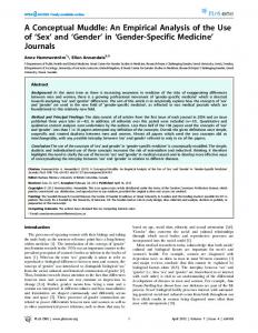
Journal of Power Technologies 93 (5) (2013) 383–394
Figure 2: Diagram of the 900 MW power unit with the CO2 capture and compression installation: (B—boiler; HP, IP, LP—high, intermediate and low pressure turbine; COND—condenser; HPH—high-pressure feed water heater; LPH—low-pressure feed water heater heater; BFP—boiler feed pump; G—generator; ABS—absorber ; STR—stripper; REB—reboiler; CFHX—cross-flow heat exchanger; FAN—flue gas fan; COOL1—flue gas precooler; COOL2—lean amine cooler; SEP1—flue gas moisture separator, flue gas cooler; SEP2—CO2 moisture separator and CO2 cooler; P1—rich amine pump; P2—lean amine pump)
— 394 —