booster were successfully tested. INTRODUCTION. The ESRF injection system is composed by a linear pre- injector and a fast cycling booster synchrotron.
Proceedings of EPAC 2004, Lucerne, Switzerland
OPERATIONAL IMPROVEMENTS IN THE ESRF INJECTION COMPLEX Y. Papaphilippou, V. Serri`ere, P. Elleaume, L. Farvacque, L. Hardy, G. Naylor, E. Plouviez, J.-L. Revol, K. Scheidt, ESRF, Grenoble, France Abstract The ESRF injection complex, comprising a 200 MeV linac, a booster accelerator with a top energy of 6 GeV and two transfer lines, has been routinely injecting beam to the storage ring since the beginning of its operation. The newly implemented injection with “front-end open” triggered several operational improvements in order to maximise the reliability of the complex. A series of diagnostics (synchrotron light monitors, striplines, fast current transformers) were implemented allowing the measurement and monitoring of several components of the injected beam. New optics models were constructed and several application systems as the closed orbit correction or tune measurements have been upgraded. The operational procedures of injection at 100MeV in the booster and the injection efficiency maximisation were renewed and improved. Further developments for the uninterrupted operation of the storage ring during injection, such as the bunch cleaning in the booster were successfully tested.
eters of the injection complex can be found in Table [1]. The new injection procedure with open front-ends imposed the implementation of new diagnostics in order to characterise the beam during the whole injection process. Operational procedures as the 100MeV injection in the booster and the TL2 optimisation for maximum injection efficiency have been reviewed. Finally, new procedures as the bunch cleaning in the booster are in the final optimisation stage. Pre-injector Energy Eext Peak current Ip Repetition rate frep Pulse duration tpulse Emittances at 200MeV �x y Energy spread at 200MeV (�E=E )in Booster Circumference C Extraction Energy Eext Nominal current Inom Harmonic number h Accelerating cycle tcycle Working point (Qx � Qy ) Momentum compaction factor � c Emittances at 6GeV (�x�ext � �x�ext ) Energy spread at 6GeV (�E=E )ext Bunch length ls
INTRODUCTION The ESRF injection system is composed by a linear preinjector and a fast cycling booster synchrotron. The electrons are created in a thermionic cathode built into a triode gun, accelerated up to 80 KeV and bunched in a buncher section before entering the linac. They are accelerated up to about 200 MeV through two 6 m-long accelerating sections, with a repetition rate of 1 or 10 Hz, depending on the required storage ring filling pattern. The beam is then guided through a transfer line (TL1), comprising two 15 bends, 8 quadrupoles and 14 steerers, and is injected “onaxis” in the booster, in a single turn, through a septum and a fast injection kicker. In that stage, the electrons are accelerated by two 5-cell LEP-type cavities to reach 6 GeV in 50 ms. The booster lattice is based on a FODO structure with a missing dipole, forming 39 cells with 12 straight sections and respecting a 3-fold symmetry. All magnets of the same family are independently powered by a resonant “white circuit”, cycling at 10 Hz. Chromaticity is corrected along the cycle by two families of sextupoles whereas the orbit is only corrected at injection with 78 independently powered steerers. The high energy beam is extracted from the booster in two stages by bringing the beam close to a small pre-septum magnet and firing a fast extraction kicker which steers the beam into the main septum magnet. The final injection stage takes place in the second transfer line TL2 where the beam is transfered through a serie of 5 booster-type dipoles, 14 quadrupoles and 17 steerers and injected into the storage ring. Some basic design param-
< 200 MeV 25 mA - 0.25A 1 - 10 Hz 1�s - 2 ns 0.5 - 1 mm rad 5 10;3 299.622 m 6 GeV 5 mA - 0.1 mA 352 50 ms (11:8� 9:8) 9.6 10;3 (120,3) nm rad 1.1 10;3 2.61 cm (87 ps)
Table 1: Linac and booster parameters. (The two numbers refer to long-short pulse operation respectively.)
DIAGNOSTICS Fluorescent screen monitors have been installed on the injector to measure the position of the beam and its transverse dimensions [2]. Four screens are installed on TL1, eight are mounted in the booster and eleven screens are located in TL2. These screens are mainly used to optimise the injection and the extraction. Concerning the transverse beam size measurements, non-destructive and more sensitive diagnostics using synchrotron light have been installed on three dipoles of the injector: two synchrotron light monitors (SLM) are used on TL1 and one in the booster. The capabilities of striplines, current transformers and fast current transformers have been extended for optimising the injection efficiency between the linac and the booster as well as the injection from the booster to the storage ring. The tune monitor and the BPM have also been improved in order to monitor the tune along the cycle and minimise the closed orbit distortion in the booster.
375
Proceedings of EPAC 2004, Lucerne, Switzerland
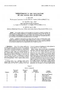
EMITTANCE MEASUREMENTS Assuming a Gaussian beam, the transverse beam emittance at the exit of the linac can be measured using the first SLM installed on TL1 and applying an upstream quadrupole strength variation. As shown in figure 1, the beam coming from the linac is made of several smaller beam-lets. The existence of multiple beam spots does not allow determining precisely the transverse emittance at the exit of the linac. However, by using various settings of the TL1 quadrupoles, we can estimate that the horizontal and vertical emittances are smaller than 65 nm rad and 70 nm rad, respectively.
ramping. At injection, the beam emittance is quite high in both planes, but it should reflect the beam instability. The vertical emittance decreases continuously during the accelerating cycle. The horizontal emittance decreases gradually until 26 ms after the injection, then the quantum fluctuation overtakes the damping and the horizontal emittance increases. The emittance blow-up at injection remains to be clearly understood. Measurements with a lower current will be made in order to check if the instabilities are due to collective effects. The pulse-to-pulse stability of the linac and the mis-match between TL1 and booster optics have to be estimated. 4500 4000
Horizontal (9 Oct) Vertival (9 Oct) Horizontal (1 Oct) Vertical (1 Oct)
Beam Size [µm]
3500 3000 2500 2000 1500 1000 500 0 0
5000
10000
15000
20000
25000
30000
35000
40000
45000
50000
Time [µm]
Figure 3: Horizontal and vertical beam size during the accelerating cycle.
Figure 1: Transverse beam spot in TL1.
0.90
Horizontal (9 Oct) Vertical (9 Oct) Horizontal (1 Oct) Vertical (1 Oct)
0.85
-6
10
Horizontal (9 Oct) Vertical (9 Oct) Horizontal (1 Oct) Vertical (1 Oct)
8 6 4
2
Emittance [m rad]
Tune
0.80
0.75
0.70
-7
10
8 6 4
2
-8
10
8 6 4
0.65 2
-9
10
0.60
0
0
5000
10000
15000
20000
25000
30000
35000
40000
45000
50000
5000
10000
15000
20000
25000
30000
35000
40000
45000
50000
Time [µm]
Time [µs]
Figure 2: Horizontal and vertical tune during the acceleration cycle. Emittance measurements were also performed in the booster [3] by using a SLM installed on the 15th dipole where the optics functions are: �x = 4:57 � 0:3m, �y = 6:99 � 0:35m and x = 0:06m. These measurements were obtained for two different tune settings shown in figure 2, with a current of 4 mA in long pulse. The horizontal and vertical beam size during the accelerating cycle are depicted in figure 3. The dots correspond to the mean values and the error bars to one standard deviation. From injection to 10 ms, the beam seems to be unstable as reflected from the large error bars in the beam size measurements. Three reasons are suspected to explain this behaviour: a) an energy error in the injected beam due to linac fluctuations; b) an orbit mismatch between TL1 and the booster; and c) a collective effect. Figure 4 shows the horizontal and vertical emittance as a function of time during the energy
Figure 4: Horizontal and vertical emittance during the accelerating cycle.
INJECTION AT 100 MEV The accelerating structures of the 200 MeV linac are powered by two 3 GHz klystrons. In case of long failure of one klystron, it is important to be able to inject at 100 MeV into the booster. This operation mode has been reviewed and the transfer efficiency optimised [4]. The essential element for injecting at lower energy is the settings of the Booster Power Supply System (BPSS). The strategy is to find optimum AC and DC current values for the dipoles and quadrupoles which allow injecting at lower energy without changing the tunes at extraction. The optimisation of BPSS settings was made in normal injection mode, i.e. 200 MeV, by increasing the injection time. Then, the second klystron was switched off to simulate a 100 MeV injection. All the
376
Proceedings of EPAC 2004, Lucerne, Switzerland
nominal current values of magnetic elements of TL1 and pulsed magnet were divided by two as well as the steerers of the booster. Then the sextupoles were used to optimise the current in the booster. Transfer efficiency above 60 % and a beam of 3.5 mA in the booster has been achieved. A succesfull test has shown that this injection mode is possible with the second klystron connected on the first accelerating section by using the RF switches on the waveguide network.
TRANSFER EFFICIENCY OPTIMISATION During 2003, the injection efficiency in TL2 was gradually degraded and reached a minimum of 20%. After an empirical retuning of a particular quadrupole setting, the efficiency reached 80%. Experimental evidence showed that the injection efficiency depended strongly on the booster extraction tunes, probably due to an orbit mismatch. A more careful scanning of quadrupole and steerer settings leaded to a maximal injection efficiency, close to 100%. It was first thought that this could be achieved by a careful adjustment of the angle/displacement of horizontal/vertical steering at the end of TL2, just before the injection elements. It was evidenced though, that it is crucial for the beam to be well positioned in the area of TL2 where the internal aperture of the vacuum chamber was shrinking from a diameter of 36 mm to a size of 25 mm horizontal 10 mm vertical. As a result, any optimisation of the TL2 steering and focusing should have included the proper vertical positioning of the electron beam on a fluorescent screen (FS9) just after this aperture drop. At some stage, the last corrector at the exit of the TL2 (CV9) and before the septum was found malfunctioning, due to a wrong electrical connection between the poles of the magnet. This effect may explain to some extent the latest difficulties to tune TL2. A strategy of TL2 optimisation was finally established [5] and the decision was taken to replace the vacuum chamber with a circular 36 mm one, so as to move the aperture limitation at the beginning of the septum.
BUNCH CLEANING
The bunch cleaning process is essential for the good performance of the few bunch modes in the storage ring, where a very demanding bunch purity of < 10 ;7 is required for time-domain dependent experiments. An efficient bunch cleaning system in the booster is necessary for the implementation of the injection with open front-ends even in these filling modes. The hardware which has been successfully tested during last year [6], includes a stripline shaker with two electrodes exciting the beam horizontaly at the betatron resonant frequency with a time selection of the parasitic bunches which are directed and lost on a scraper. The procedure has to be done at the beginning of the cycle (around 5 ms or 300 MeV) due to the limited power of the stripline amplifier. The chromaticity has to be close to zero in order to ensure a correct tune tracking for the cleaning process. On the other hand, at this low energy, the damping time is very large and the beam may remain excited due to injection elements mis-match or linac fluctuations, thereby limiting the cleaning efficiency. The stripline electrodes can provide an accurate fast position signal for minimising the transverse oscillations of the injected beam and for tracking their source. In Fig. 5, the horizontal turn-by-turn position is shown during the first few ms after injection. The signal is characterised by long period oscillations associated to energy mismatch, modulated by transverse oscillations due to injection element mis-tuning. These oscillations can be eliminated by changing the injection time and resteering the beam correctly into the booster, thereby facilitating the bunch cleaning process.
PERSPECTIVES In the immediate future, the bunch cleaning procedure has to be fully operational, by tracing the optimal beam conditions during the booster cycle for efficient cleaning. This will need the characterisation of beam parameters as the bunch length during injection, and existing diagnostics as the streak camera are refurbished for this purpose. The booster orbit control is being replaced with an application similar to the one of the storage ring permitting an efficient correction using SVD algorithms. At the same time, response matrix measurements are being done in order to refine the booster model and permit the automatic control of the tune and the chromaticity. A project of emittance measurements in TL2 is underway in order to establish the optics model and refine it, for achieving comfortable beam transfer and maximise the injection efficiency. We would like to thank the ESRF RF and operation groups for their help in the course of these studies.
REFERENCES
Figure 5: Turn-by-turn position signal from the ESRF booster at injection. 377
[1] ESRF Foundation Phase Report, Chapter III, ESRF, 1987. [2] K. Scheidt, “Upgrade of the ESRF Fluorescent Screen Monitors”, DIPAC 2003. [3] Y. Papaphilippou et al., ESRF Tech. Note 20-03/MDT, 2003. [4] Y. Papaphilippou et al., ESRF Tech. Note 26-03/MDT, 2003. [5] P. Elleaume et al., ESRF Technical Note 17-03/MDT, 2003. [6] E. Plouviez and N. Michel, these proceedings.