Progress article Published online: 29 october 2010 | doi: 10.1038/nphoton.2010.196
Optical arbitrary waveform generation Steven T. Cundiff1* and Andrew M. Weiner2 Optical arbitrary waveform generation will allow waveforms to be synthesized at optical frequencies but with the flexibility currently available at radiofrequencies. This technique is enabled by combining frequency comb technology, which produces trains of optical pulses with a well-defined frequency spectrum, with pulse shaping methods, which are used to transform a train of ultrashort pulses into an arbitrary waveform. To produce a waveform that fills time, the resolution of the shaper must match the repetition rate of the original pulse train, which in turn must have a comb spectrum that is locked to the shaper. Here, we review the current efforts towards achieving optical arbitrary waveform generation and discuss the possible applications of this technology.
A
lthough the electromagnetic spectrum is a continuum, a strong distinction is typically drawn between electronics and optics. This distinction is due, in part, to the very different technologies used for electronics and optics. A further distinction is that electronic devices typically generate and measure electric field waveforms, whereas optical devices can generate and measure only intensity waveforms because the frequencies involved are much higher. For any intensity waveform there is a continuous family of electric field waveforms that differ by the overall phase. Furthermore, in optics there have been significant limits on what waveforms can be generated, whereas electronic devices have been used to generate arbitrary waveforms for several decades. Over the past decade, advances in optics have allowed the phase of an electric field, with respect to the corresponding intensity waveform, to be measured and controlled. These techniques are referred to as ‘optical frequency combs’ because the evolution of the electric field phase in a train of pulses causes a shift in the corresponding frequency spectrum, which is a comb of equally spaced sharp spectral lines1. Optical frequency comb technology has revolutionized optical frequency metrology and optical atomic clocks2, and has enabled the production of attosecond pulses3. The development of comb technology has also spurred recent work on the generation of arbitrary waveforms at optical frequencies. Techniques for shaping ultrashort optical pulses have existed for around two decades4. However, these techniques have significant limitations. First, the duration of the output pulses is limited by the spectral resolution of the pulse shaper and is less than the time between pulses. Thus, the output pulse train does not fill time; that is, there are gaps between pulses. Second, typically the pulses are all identical. An arbitrary waveform cannot be produced within these limitations. Producing a waveform that fills time requires a pulse shaper with a spectral resolution that matches the spacing of the comb lines of the input pulse train. Such high resolution is only useful if the frequency comb is stable and aligned with the pulse shaper 5 — hence the need for frequency comb technology. Sometimes known as ‘line-by-line pulse shaping’, pulse shaping with a resolution matching the comb was demonstrated a few years ago5–7. However, the phase and/or amplitude of the individual comb lines were manipulated by ‘masks’ that are essentially static. To produce truly arbitrary optical waveforms requires that the pulse shaper can be updated for each pulse — a goal that has not yet been reached, but is being actively pursued in many laboratories around the world.
Generation of comb spectra
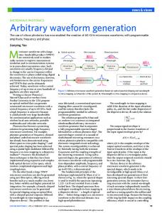
There are two main sources of frequency combs: mode-locked lasers and optical frequency comb generators based on the electro-optic modulation of a continuous-wave laser. Although modelocked lasers dominate in most applications, both sources are currently being used for efforts towards optical arbitrary waveform generation. Mode-locked lasers produce a regular train of ultrashort optical pulses8,9, with typical pulse durations ranging from ~10 fs to a few picoseconds. Repetition rates, fr, range from tens of megahertz to a few tens of gigahertz. Although Ti:Sapphire lasers using Kerr-lens mode-locking are the most common in ultrafast optics laboratories, other technologies such as fibre lasers mode-locked by nonlinear polarization rotation are also used extensively. Prior to the development of frequency comb technology, mode-locked lasers were primarily used in applications exploiting either the high time resolution or the high peak power provided by ultrashort pulses. These applications were sensitive to the properties of an isolated pulse, and the fact that mode-locked lasers produce a train of pulses was not important. An individual ultrashort pulse has a broad optical spectrum with a width that is inversely proportional to the minimum (chirp-free) duration. Because the output of a mode-locked laser consists of a regular train of pulses, the optical spectrum is actually a comb of sharp spectral lines beneath an envelope that is the spectrum of a single pulse. The comb lines are spaced by fr, making them only observable in a very high resolution spectrum. If all of the pulses in the train have an identical electric field, then the comb line frequencies would simply be integer multiples of fr. However, the pulses are not all identical because the pulse circulating inside the laser experiences a shift between the phase of the carrier wave, which travels at the phase velocity, and the peak of the intensity envelope, which travels at the group velocity. The evolution of this phase, known as the carrier–envelope phase, ϕce, shifts the comb spectrum by the offset frequency to give f0 = fr Δϕce/2π, where Δϕce is the pulse-topulse change in ϕce. Thus, the optical frequencies of the comb lines are νn = nfr + f0, where n is an integer. The relationship between the time and frequency domains is shown in Fig. 1a. The development of methods to measure f0 was the key breakthrough in producing useful frequency combs using mode-locked lasers10–12. The basic idea, known as self-referencing, is to compare the low- and high-frequency wings of the spectrum by frequency doubling the low-frequency wing through second-harmonic
JILA, National Institute of Standards and Technology and University of Colorado, Boulder, Colorado 80309-0440, USA. 2Department of Electrical and Computer Engineering, Purdue University, West Lafayette, Indiana 47907-2035, USA. *e-mail:
[email protected]
1
760
nature photonics | VOL 4 | NOVEMBER 2010 | www.nature.com/naturephotonics
© 2010 Macmillan Publishers Limited. All rights reserved.
progress article
Nature photonics doi: 10.1038/nphoton.2010.196 a Time domain
1 Δ2φ ce
Δφ ce
Ideal
τ
Time
1/fr
Pulse magnitude (a.u.)
Electric field
0. 5 0
0
Current
0 −4
1/τ
f0
b Grating
Lens
Output waveform
νn = nfr + f0 Spatial light modulator
Low resolution
0. 5
Frequency domain
fr
High resolution
0. 5
Frequency
Lens
Grating
Input pulse
Figure 1 | Optical arbitrary waveform generation. a, The correspondence between the time (top) and frequency (bottom) domains for a pulse train with evolving phase and duration τ. b, Schematic of a pulse shaper based on spectral decomposition.
generation. The frequency difference between a high-frequency comb line and the closest doubled low-frequency comb line is f0, which is easily measured through heterodyne methods. This measurement can be used in a phase-locked loop13 to fix f0 and thus produce a stable comb with specified comb line frequencies. Selfreferencing requires a very broad spectrum to ensure that there is significant power at two wavelengths separated by an octave (that is, separated by a factor of two in frequency). Such a spectrum can be achieved by external broadening in a nonlinear medium such as a microstructure fibre14,15, or it can be produced directly by the mode-locked laser 16–19. Alternative methods of producing combs are also of interest, particularly for generating combs at high rates (>10 GHz). For example, mode-locked lasers at rates of 10 GHz or even 40 GHz have been demonstrated, in which the optical frequency is not self-referenced but is instead referenced to an intracavity etalon20 or an external molecular absorption cell21. Other approaches start with a continuous-wave laser and use a phase modulator to produce multiple sidebands spaced by the modulator frequency 22. In one recent example, a very large modulation index was obtained using a total of three telecommunications phase modulators, yielding 61 comb lines, each spaced by 25 GHz (ref. 23). Such sources could potentially replace the arrays
−2
0 Time (1/frep)
2
4
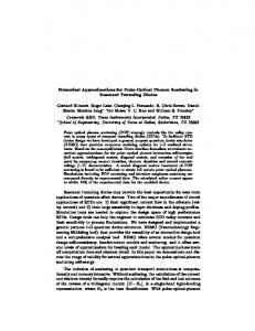
Figure 2 | Interplay between spectral resolution and temporal response. The repetition rate should double if an amplitude mask that blocks every other comb line is introduced. However, this ideal case (top) is not realizable, and the actual waveform depends on the resolution, which is adjustable by the spot size in this simulation. At high resolution the switching is slow, while the fidelity of the masked waveform is good (middle). At low resolution the switching is fast, but the waveform fidelity is poor (bottom). A compromise between resolution and fidelity must be made. Figure reproduced with permission from ref. 32, © 2008 OSA.
of distributed feedback lasers currently used to generate the multitude of carrier frequencies required for wavelength-division-multiplexed optical communications. A larger number of sidebands can be produced if the modulator is placed in an optical cavity that has a free spectral range commensurate with the modulation frequency 24,25. Compared with combs generated by mode-locked lasers, these continuous-wave approaches have the advantage that the frequencies of the comb lines are known relative to the optical frequency of the laser, and also that it is easier to generate combs with large spacing (typical values are 5–25 GHz). The main disadvantage is that self-referencing cannot be implemented because of the narrow comb bandwidth, and thus the absolute frequencies are not known. However, current efforts towards optical arbitrary waveform generation (OAWG) manipulate only a relatively small number of comb lines, and the absolute frequency does not matter; thus, combs produced by phase modulation can be easier to use than those produced by a mode-locked laser.
Pulse shaping
In pulse shaping, powerful Fourier synthesis methods are used to generate user-defined femtosecond optical waveforms. As shown in Fig. 1b, an incident femtosecond pulse is decomposed into its constituent spectral components by a spectral disperser (usually a grating) and a focusing element (a lens or a curved mirror). A spatially patterned mask then modulates the phase and amplitude (and sometimes the polarization) of the spatially dispersed spectral components. A shaped output pulse is obtained after the spectral components are recombined by a second lens and grating, with the pulse shape given by the Fourier transform of the pattern transferred by the mask onto the spectrum. This ‘4f pulse shaping’ arrangement is also frequently implemented in a reflection geometry, in which a mirror placed after the spatial mask directs the field back through the first lens and grating. Pulse shaping masks were originally implemented through microlithographic patterning techniques26, and subsequently using programmable spatial light modulators4,27,28, acousto-optic modulators29, holographic masks, deformable mirrors and micromirror arrays. Pulse shaping is most commonly implemented using programmable liquid-crystal modulator arrays4,27,28, which allow independent, simultaneous grey-level control of both spectral amplitude and phase. A
nature photonics | VOL 4 | NOVEMBER 2010 | www.nature.com/naturephotonics
© 2010 Macmillan Publishers Limited. All rights reserved.
761
progress article a
Nature photonics doi: 10.1038/nphoton.2010.196 a
b
8.5 GHz
Frequency (GHz)
0
π 1,541.7
c
1,541.9 1,542.1 Wavelength (nm)
11 GHz
–200 –100
d
0 100 Time (ps)
200
0
b
–2 –1 0 1 2
c
–100 0 100 Frequency (GHz)
π 1,541.7
1,541.9 1,542.1 Wavelength (nm)
–200 –100
0 100 Time (ps)
200
Figure 3 | Offset frequency sensitivity in line-by-line pulse shaping. a,b, Optical spectrum analyser measurement of two relatively stable spectral lines at 8.5 GHz (a), along with sampling scope traces with phase modulations of 0 and π on a single spectral line (b). The traces are scanned 100 times. c,d, Optical spectrum analyser measurement of two relatively unstable spectral lines at 11 GHz (c), along with sampling scope traces with phase modulations of 0 and π on a single spectral line (d). The traces are scanned 100 times. Figure reproduced with permission from ref. 5, © 2005 OSA.
detailed theoretical discussion of pulse shaping is given in ref. 9. Some reviews of pulse shaping and its applications are given in refs 4,30,31. Using these methods, femtosecond pulses can be engineered into complex optical signals, almost arbitrarily and according to specification. A key point is that waveform synthesis is achieved by parallel modulation in the frequency domain, which is achieved by spatial modulation of the dispersed optical frequency spectrum. Thus, waveforms with serial modulation bandwidths as high as hundreds of terahertz can be generated and manipulated without any ultrafast modulators. Recent research has aimed to extend pulse shaping to a hyperfine spectral resolution of a few gigahertz and below, which requires the manipulation of waveforms with time apertures extending to hundreds of picoseconds or longer. This is in stark contrast with today’s conventional resolutions of tens or hundreds of gigahertz and time apertures of picoseconds or tens of picoseconds. Such a resolution capability is critical for processing optical signals at data rates of tens of gigabits per second, as well as for line-by-line shaping of frequency comb sources for OAWG, which is discussed in the following section. Note that the term ‘OAWG’ is often used inconsistently in the literature. ‘Line-by-line shaping’ is sometimes called ‘static OAWG’, with the ‘static’ often being omitted. In this case, the term ‘dynamic OAWG’ is used to refer to true OAWG, in which the waveform is updated for every pulse.
Optical arbitrary waveform generation
The starting point for producing an arbitrary optical waveform is a train of identical optical pulses with sufficient bandwidth. As discussed above, the pulse train may be produced either by a modelocked laser or through modulation of a continuous-wave laser. If the pulse train is to be converted into an arbitrary waveform by spectral decomposition (as is typically done), the spectrum must be decomposed with a resolution equal to the repetition rate of the pulse train. This condition is necessary for the output waveform to fill time. In addition, the elements used to modulate the individual frequency components must be updated at the repetition rate; 762
Figure 4 | Frequency combs spread in two dimensions using a VIPA and diffraction grating. a, Frequency comb from a 1 GHz repetition rate Ti:Sapphire laser. Each spot corresponds to a comb line. Horizontal spacing between columns is 25 GHz and vertical spacing is 1 GHz (image courtesy of J. Willits). b, 10 GHz comb obtained by modulating a continuouswave laser followed by spectral broadening in a fibre. Horizontal spacing between columns is 200 GHz (VIPA free spectral range), vertical spacing is 20 GHz (every other comb line is eliminated). The offset between columns is introduced to realize a shaped waveform. c, 2,200 individual modes from a 1 GHz repetition rate laser filtered by a cavity to 3 GHz. The data repeat every 50 GHz in the vertical direction, and a subset of unique data is enclosed by the black box. Image acquired after passing through an iodine cell. Numerous modes are attenuated by the iodine vapour, thus providing a unique fingerprint. The circled modes are a reference laser used for calibration. Figure reproduced with permission from: b, ref. 62, © 2008 OSA; c, ref. 36, © 2007 NPG.
otherwise the waveform is limited to repeating every period of the input pulse train. From a technological perspective, these two criteria are in direct competition. The spectral resolution requirement is more easily achieved at higher repetition rates, whereas the modulation requirement is more easily achieved at lower repetition rates. Currently, it seems that frequencies of around 1–10 GHz are the best compromise between the two. An obvious concern is that modulation occurs at the same frequency at which the spectrum is being resolved. Although the modulators will generate new frequency components on a given comb line, these components will be at the wrong spatial location and hence do not recombine properly. Simulations show that fairly good waveforms can be produced for an appropriate choice of resolution32. If the resolution is too low, then the waveform fidelity is compromised, whereas if it is too high, then the switching speed is limited. An example calculation of this compromise is shown in Fig. 2 for the case of abrupt switching on a mask that blocks every other comb line, thus doubling the repetition rate of the pulse train. The resolution is varied by changing the spot size in the pulse shaper. If the resolution is too low, then the fidelity of the waveform is low; in this case the pulses in the double-repetition-rate train are unequal. If the resolution is too high, then the transition between waveforms extends over many pulse periods. An approach to address the competition between resolution and nature photonics | VOL 4 | NOVEMBER 2010 | www.nature.com/naturephotonics
© 2010 Macmillan Publishers Limited. All rights reserved.
progress article
Nature photonics doi: 10.1038/nphoton.2010.196
–100
0.3 0.2 0.1 0 –100
Time (ps)
Unwrapped phase (rad)
0 Time (ps)
Intensity (a.u.)
Intensity (a.u.)
–200
–50
15 π
100
c
0.2 0.1 0
50
Time (ps)
e
Intensity (a.u.)
10
1,536
1,537 1,538 Wavelength (nm)
1,539
1,540
–200 0 200 Frequency (GHz)
Phase (1 rad div–1)
Phase (1 rad div–1)
Intensity (a.u.)
1,540
Intensity (5 dB div–1)
g
Time (50 ps div–1)
1,539
Phase (1 rad div–1)
Phase (1 rad div–1)
f
0 Time (ps)
1,537 1,538 Wavelength (nm)
π
0 1,535
d
–10
1,536
2π
0.3
0
0
−15 π 1,535
200
Wrapped phase (rad)
Intensity (a.u.)
1
0
b
Measurement Calculation
Intensity (5 dB div–1)
a
Frequency (100 GHz div–1)
Figure 5 | Static OAWG waveforms. a–c, Spectral phase shaping of >100 lines at 5 GHz spacing: linear spectral phase (delayed pulse) in half of spectrum and cubic spectral phase in other half. Both wrapped (actual) phase and unwrapped phase are shown. d–g, Generation of communications waveforms. 9-bit 360 Gb s–1 data packet (d) and corresponding spectrum (e); 40-bit 400 Gb s–1 data packet (f) and corresponding spectrum (g). For time domain waveforms (d,f), intensity and phase data are shown as blue and red solid lines, respectively, with targets shown as dots or dashes. For spectra (e,g), intensity and phase data are blue stems and red circles, respectively, with targets indicated as ‘x’. Figure reproduced with permission from: a–c, ref. 7, © 2007 NPG; d–g, ref. 33, © 2009 OSA.
switching speed is suggested in ref. 33, in which waveforms are synthesized in partially overlapping spectral slices and pre-distorted to account for spectral filtering effects. If the spectral resolution of the pulse shaping is equal to the repetition rate of the input train — known as line-by-line pulse shaping — then alignment between the frequency comb of the pulse train and the modulator elements becomes an issue. A static misalignment can increase losses, and may even render the pulse shaper opaque. Furthermore, fluctuations in the comb offset frequency will map onto fluctuations in the generated waveform. Figure 3 shows a simple demonstration of the sensitivity to the comb offset frequency. Achieving the spectral resolution needed to separate comb lines is a challenge. The ruled diffraction gratings typically used in traditional bulk optics pulse shaping can only resolve comb lines from a relatively high repetition rate source (~ 5 GHz), and to do so requires a beam diameter of several centimetres, large gratings and a long focal length lens (~1 m). These requirements result in a bulky experimental set-up. The most common approach
for achieving even higher spectral resolution in a more compact arrangement is to use a virtual imaged phased array (VIPA), which is essentially a side-entrance Fabry–Pérot etalon34. A VIPA provides very high angular dispersion, but also has a free spectral range (just as for a regular etalon), with frequencies separated by a free spectral range going in the same output direction as each other. However, the free spectral range is typically large enough such that the comb lines going in a given direction can be separated with an ordinary grating. A VIPA–grating pair is typically configured such that they provide angular dispersion at right angles to one another 35 and spread the input spectrum across two dimensions; thus, the frequency comb becomes a frequency ‘brush’36. Examples demonstrating the resolution of individual comb lines spread in two dimensions are shown in Fig. 4. High spectral resolution has also been achieved using an arrayed waveguide router 6,37–39. This approach has the advantage of being easily integrated with other waveguide devices such as modulators to form pulse-shaper chips. Operation in the line-byline regime is an especially suitable application of such devices,
nature photonics | VOL 4 | NOVEMBER 2010 | www.nature.com/naturephotonics
© 2010 Macmillan Publishers Limited. All rights reserved.
763
progress article
Nature photonics doi: 10.1038/nphoton.2010.196
as the optical comb may be placed at the centre of their discrete transmission channels. However, the minimum repetition rate is currently limited to 10 GHz, because increasing the resolution requires increasing the area of the chip, which becomes incompatible with the need for very low phase errors in the waveguide array. On the other hand, high-speed modulation is easier to achieve in a waveguide device than with bulk optical modulators, provided that the waveguides are formed from materials that support highspeed modulation, such as certain compound semiconductors (InP, for example). Recent research includes implementation of an InP tunable integrated pulse shaper with coarse (200 GHz) channel spacing 40 and the fabrication methods suitable for realizing InP-based arrayed waveguide routers with a close channel spacing (10–20 GHz) that is appropriate for OAWG41. However, high-fidelity pulse shaping in the line-by-line regime has so far been limited to devices based on the more mature silica-based technology, which relies on thermo-optic modulation and is consequently slow. Full OAWG, including simultaneous spectral resolution at the comb spacing and modulation at the repetition rate, has not yet been achieved. Line-by-line pulse shaping has been achieved for as many as 100 comb lines spaced by 5 GHz using traditional diffraction gratings and a liquid-crystal spatial modulator 7. Line-by-line pulse shaping has also been achieved with 32 and 40 comb lines using a silica-based arrayed waveguide router pulse shaper with resistive-heater-based Mach–Zehnder phase and amplitude modulation for each wavelength6,33. Examples of waveforms generated by both techniques are shown in Fig. 5.
Optical arbitrary waveform measurement
Methods for the full characterization of ultrashort-pulse fields are well-established9,42–44, and include self-referenced techniques such as frequency-resolved optical gating and spectral shearing interferometry (known as SPIDER in conventional ultrafast optics42) and non-self-referenced techniques such as spectral interferometry. However, the unique attributes of the fields generated by line-byline pulse shaping lead to new challenges in waveform characterization. For example, these fields may exhibit a 100% duty cycle, with shaped waveforms spanning the full time-domain repetition period of the frequency comb, spectral amplitude and phase changing abruptly from line-to-line, and large time–bandwidth products. In contrast, conventional methods for characterizing ultrashort pulse fields are typically used to measure low-duty-cycle pulses that are isolated in time and have a smoothly varying spectra and relatively low time–bandwidth product. These methods are geared towards low spectral resolution and are not generally compatible with the rapid spectral changes that are a hallmark of line-by-line pulse shaping. Several efforts have been made to adapt ultrafast measurement techniques for the characterization of static OAWG waveforms. For example, frequency-resolved optical gating has been adapted for measuring relatively simple OAWG signals45. Several recent papers46–49 focus on applying frequency-domain ultrashort-pulse characterization approaches, such as spectral interferometry and spectral shearing interferometry, to OAWG signals, thereby allowing parallel data acquisition. Such techniques measure spectral phase through frequency-dependent interference with a delayed auxiliary pulse. Conventionally, the need to unambiguously retrieve both quadratures of the spectral interference means that the delay must exceed the pulse duration. However, for OAWG waveforms with intrinsically large time apertures, this results in very difficult spectral resolution requirements. Accordingly, zerodelay versions of these techniques, in which both quadratures of the interference signal are acquired separately, have recently been implemented, thereby relaxing spectral resolution requirements to the comb spacing and enabling practical implementation46–49. The 764
spectral interferometry flavour of such measurements has been demonstrated to allow high-precision dispersion measurements for fibre spans of up to 50 km (ref. 48) — orders of magnitude greater than the distances over which interferometric measurements of spectral phase have previously been achieved. A key point here is the use of frequency combs as the light source, as the periodicity and long coherence time of a comb permits successful interferometry even with a large delay imbalance between the interferometer arms. Single-shot characterization of individual OAWG waveform frames has been achieved using spectral interferometry approaches, which can achieve the required high sensitivity because they only use linear optics46,49. This capability will be needed for dynamic OAWG measurement, in which waveforms will be updated on a pulse-by-pulse basis, and should enable both the intensity and phase of non-recurring transient events to be captured in advanced lightwave systems (not possible with today’s sampling-based characterization methods). Demonstrations of dynamic waveform measurement46,49 have so far relied on external switching between two different static waveforms, such as that obtained from two different static pulse shapers, rather than on the true pulse-by-pulse update of a single shaper. Time lens approaches, which magnify the timescale of burst waveforms to durations compatible with real-time oscilloscope technology, have also been demonstrated for the single-shot capturing of OAWG intensity profiles, but not phase profiles50,51. Finally, real-time measurement over extended record lengths has recently been demonstrated by optical homodyne detection followed by high-speed digitization of in-phase and quadrature field components — similar to techniques now popular in state-of-the-art lightwave communications receivers, but extended to multiple overlapping wavelength bands using a frequency comb as the local oscillator 52.
Applications
OAWG is still in its infancy, and its applications are still a matter of speculation. Many of the applications of traditional pulse shaping will benefit from the superior capabilities provided by OAWG. These include coherent control over quantum mechanical processes such as ultrafast chemical reactions, the manipulation of high-field laser–matter interactions such as the generation of attosecond pulses, and photonically enabled generation and processing of ultrabroadband radiofrequency electrical signals. There may of course be new, unknown applications that will be enabled by the unique capabilities of OAWG. A recent example of coherent control is the creation of a high phase-space density of polar molecules53 using a pair of continuous-wave lasers locked to the frequency comb produced by a mode-locked laser. OAWG techniques could allow the same result to be achieved by directly producing the desired phase-coherent waveform, rather than by using a continuous-wave laser. Coherent control of cold rubidium atoms using a comb of pulses shaped through conventional techniques has also been demonstrated54. OAWG will add a new dimension to this control scheme by allowing the pulse shape to change dynamically. OAWG may also impact new high-sensitivity broadband spectroscopy techniques based on femtosecond comb enhancement cavities55 and massively parallel read-out36 by allowing the generation of interrogation fields optimized for the detection of a particular species. One possible application of OAWG is in optical communications, where it enables the synthesis of terabit-per-second signals by exploiting complex modulation formats such as quadrature amplitude modulation. This concept has recently been demonstrated using static line-by-line shaping to generate repeated waveforms33. With the advent of OAWG, in which the waveform can be changed for every pulse, it will become possible to transmit data at terabit-per-second rates using a single light source. The long nature photonics | VOL 4 | NOVEMBER 2010 | www.nature.com/naturephotonics
© 2010 Macmillan Publishers Limited. All rights reserved.
Nature photonics doi: 10.1038/nphoton.2010.196 coherence times associated with frequency combs will enable new approaches for coherent detection by serving as the local oscillator at the receiver 56. Combined with a transmitter that utilizes OAWG, this approach may lead to significant improvements in communication bandwidth. OAWG transmitters may also impact new concepts for carrier-phase-locked optical communications, where they are proposed to exploit interchannel coherence to mitigate linear and nonlinear interference between different wavelength channels57,58. Light detection and ranging (LIDAR) uses broadband optical waveforms to achieve high-precision distance measurements, with a precision that improves as the bandwidth increases. One common choice for such systems is to use waveforms with a simple frequency sweep (or chirp), although this sweep must be very linear. The current state-of-the-art LIDAR systems are based on sweeping the frequency of a continuous-wave laser using a self-heterodyne technique to achieve a resolution of 86 nm at a range of 1.5 m (ref. 59). Recent experiments that simultaneously exploited the optical phase and radiofrequency timing coherence of a pair of fibre-laser-based frequency combs have demonstrated ranging precision down to 5 nm (ref. 60). Using OAWG, it should be possible to generate a perfectly linear frequency sweep over a greater bandwidth and at a higher chirp rate, yielding improved resolution and faster update for chirp-based systems, or generate waveforms that allow the designer to manipulate the trade-off, or ambiguity function, between range and velocity resolution in comb-based laser radar, much like traditional radar engineers select radiofrequency waveforms based on their ambiguity function performance. A very speculative application of OAWG is to implement the ideas of synthetic aperture radar at optical frequencies. In synthetic aperture radar, a waveform is emitted and the return signal recorded coherently while the transmitter and receiver move along a known trajectory (typically on an airplane or satellite)61. Because the signal is recorded coherently, it is possible to numerically produce an image with a resolution limited by the distance travelled rather than the collection aperture. Using OAWG, a similar concept could be implemented at optical frequencies, which would avoid the large lenses usually needed for producing highresolution images.
Outlook and summary
The ability to generate optical arbitrary waveforms has become conceivable due to enabling advances in the generation of optical frequency combs and high-resolution spectral dispersers. Although OAWG has not yet been achieved, the intermediate goal of static line-by-line pulse shaping has already been demonstrated. OAWG will be demonstrated in the near future, although probably for only a small number of comb lines. Such a demonstration will trigger new applications, including the translation of ideas from the radiofrequency domain to optical frequencies.
References
1. Ye, J. & Cundiff, S. T. Femtosecond optical frequency comb technology (Springer, 2005). 2. Cundiff, S. T. & Ye, J. Femtosecond optical frequency combs. Rev. Mod. Phys. 75, 325–342 (2003). 3. Krausz, F. & Ivanov, M. Attosecond physics. Rev. Mod. Phys. 81, 163–234 (2009). 4. Weiner, A. M. Femtosecond pulse shaping using spatial light modulators. Rev. Sci. Instr. 71, 1929–1960 (2000). 5. Jiang, Z., Seo, D. S., Leaird, D. E. & Weiner, A. M. Spectral line by line pulse shaping. Opt. Lett. 30, 1557–1559 (2005). 6. Fontaine, N. K. et al. 32 phase x 32 amplitude optical arbitrary waveform generation. Opt. Lett. 32, 865–867 (2007). 7. Jiang, Z., Huang, C. B., Leaird, D. E. & Weiner, A. M. Optical arbitrary waveform processing of more than 100 spectral comb lines. Nature Photon. 1, 463–467 (2007). 8. Ippen, E. P. Principles of passive-mode locking. Appl. Phys. B 58, 159–170 (1994). 9. Weiner, A. M. Ultrafast optics (Wiley, 2009).
progress article 10. Holzwarth, R. et al. Optical frequency synthesizer for precision spectroscopy. Phys. Rev. Lett. 85, 2264–2267 (2000). 11. Jones, D. J. et al. Carrier-envelope phase control of femtosecond mode-locked lasers and direct optical frequency synthesis. Science 288, 635–639 (2000). 12. Telle, H. R. et al. Carrier-envelope offset phase control: A novel concept for absolute optical frequency measurement and ultrashort pulse generation. Appl. Phys. B 69, 327–332 (1999). 13. Cundiff, S. T., Ye, J. & Hall, J. L. Optical frequency synthesis based on modelocked lasers. Rev. Sci. Instr. 72, 3749–3771 (2001). 14. Ranka, J. K., Windeler, R. S. & Stentz, A. J. Visible continuum generation in air-silica microstructure optical fibers with anomalous dispersion at 800 nm. Opt. Lett. 25, 25–27 (2000). 15. Ranka, J. K., Windeler, R. S. & Stentz, A. J. Optical properties of high-delta airsilica microstructure optical fibers. Opt. Lett. 25, 796–798 (2000). 16. Bartels, A., Heinecke, D. & Diddams, S. A. 10-GHz self-referenced optical frequency comb. Science 326, 681–681 (2009). 17. Fortier, T. M., Bartels, A. & Diddams, S. A. Octave-spanning Ti:Sapphire laser with a repetition rate >1 GHz for optical frequency measurements and comparisons. Opt. Lett. 31, 1011–1013 (2006). 18. Fortier, T. M., Jones, D. J. & Cundiff, S. T. Phase stabilization of an octavespanning Ti:Sapphire laser. Opt. Lett. 28, 2198–2200 (2003). 19. Matos, L. et al. Direct frequency comb generation from an octave-spanning, prismless Ti:Sapphire laser. Opt. Lett. 29, 1683–1685 (2004). 20. Quinlan, F., Willliams, C., Ozharar, S., Gee, S. & Delfyett, P. J. Self-stabilization of the optical frequencies and the pulse repetition rate in a coupled optoelectronic oscillator. J. Lightwave Technol. 26, 2571–2577 (2008). 21. Nakazawa, M., Kasai, K. & Yoshida, M. C2H2 absolutely optical frequencystabilized and 40 GHz repetition rate stabilized, regeneratively mode-locked picosecond erbium fiber laser at 1.53 μm. Opt. Lett. 33, 2641–2643 (2008). 22. Kobayash,T., Sueta, T., Matsuo, Y. & Cho, Y. High repetition rate optical pulsegenerator using a Fabry–Perót electrooptic modulator. Appl. Phys. Lett. 21, 341–343 (1972). 23. Yamamoto, T., Komukai, T., Suzuki, K. & Takada, A. Multicarrier light source with flattened spectrum using phase modulators and dispersion medium. J. Lightwave Technol. 27, 4297–4305 (2009). 24. Kourogi, M., Nakagawa, K. & Ohtsu, M. Wide-span optical frequency comb generator for accurate optical frequency difference measurement. IEEE J. Quant. Electron. 29, 2693–2701 (1993). 25. Ye, J., Ma, L. S., Daly, T. & Hall, J. L. Highly selective terahertz optical frequency comb generator. Opt. Lett. 22, 301–303 (1997). 26. Weiner, A. M., Heritage, J. P. & Kirschner, E. M. High-resolution femtosecond pulse shaping. J. Opt. Soc. Am. B 5, 1563–1572 (1988). 27. Weiner, A. M., Leaird, D. E., Patel, J. S. & Wullert, J. R. Programmable shaping of femtosecond pulses by use of a 128-element liquid-crystal phase modulator. IEEE J. Quant. Electron. 28, 908–920 (1992). 28. Wefers, M. M. & Nelson, K. A. Generation of high-fidelity programmable ultrafast optical waveforms. Opt. Lett. 20, 1047–1049 (1995). 29. Dugan, M. A., Tull, J. X. & Warren, W. S. High resolution acousto-optic shaping of unamplified and amplified femtosecond laser pulses. J. Opt. Soc. Am. B 14, 2348–2358 (1997). 30. Goswami, D. Optical pulse shaping approaches to coherent control. Phys. Rep. 374, 385–481 (2003). 31. Nuernberger, P., Vogt, G., Brixner, T. & Gerber, G. Femtosecond quantum control of molecular dynamics in the condensed phase. Phys. Chem. Chem. Phys. 9, 2470–2497 (2007). 32. Willits, J. T., Weiner, A. M. & Cundiff, S. T. Theory of rapid-update line by line pulse shaping. Opt. Express 16, 315–327 (2008). 33. Geisler, D. J. et al. Modulation-format agile, reconfigurable Tb/s transmitter based on optical arbitrary waveform generation. Opt. Express 17, 15911–15925 (2009). 34. Shirasaki, M. Large angular dispersion by a virtually imaged phased array and its application to a wavelength demultiplexer. Opt. Lett. 21, 366–368 (1996). 35. Xiao, S. & Weiner, A. M. 2-D wavelength demultiplexer with potential for >= 1000 channels in the C-band. Opt. Express 12, 2895–2902 (2004). 36. Diddams, S. A., Hollberg, L. & Mbele, V. Molecular fingerprinting with the resolved modes of a femtosecond laser frequency comb. Nature 445, 627–630 (2007). 37. Fontaine, N. K. et al. Compact 10 GHz loopback arrayed-waveguide grating for high-fidelity optical arbitrary waveform generation. Opt. Lett. 33, 1714–1716 (2008). 38. Miyamoto, D. et al. Waveform-controllable optical pulse generation using an optical pulse synthesizer. IEEE Photon. Tech. Lett. 18, 721–723 (2006). 39. Takiguchi, K., Okamoto, K., Kominato, I., Takahashi, H. & Shibata, T. Flexible pulse waveform generation using silica waveguide based spectrum synthesis circuit. Electron. Lett. 40, 537–538 (2004). 40. Heck, M. J. R. et al. Design, fabrication, and characterization of an InP-based tunable integrated optical pulse shaper. IEEE J. Quant. Electron. 44, 370–377 (2008).
nature photonics | VOL 4 | NOVEMBER 2010 | www.nature.com/naturephotonics
© 2010 Macmillan Publishers Limited. All rights reserved.
765
progress article
Nature photonics doi: 10.1038/nphoton.2010.196
41. Baek, J. H. et al. 10-GHz and 20-GHz channel spacing high-resolution AWGs on InP. IEEE Photon. Tech. Lett. 21, 298–300 (2009). 42. Iaconis, C. & Walmsley, I. A. Spectral phase interferometry for direct electricfield reconstruction of ultrashort optical pulses. Opt. Lett. 23, 792–794 (1998). 43. Lepetit, L., Cheriaux, G. & Joffre, M. Linear techniques of phase measurement by femtosecond spectral interferometry for applications in spectroscopy. J. Opt. Soc. Am. B 12, 2467–2474 (1995). 44. Trebino, R. Frequency-resolved optical gating: The measurement of ultrafast laser pulses (Kluwer, 2000). 45. Scott, R. P. et al. High-fidelity line by line optical waveform generation and complete characterization using FROG. Opt. Express 15, 9977–9988 (2007). 46. Fontaine, N. K., Scott, R. P., Heritage, J. P. & Yoo, S. J. B. Near quantum-limited, single-shot coherent arbitrary optical waveform measurements. Opt. Express 17, 12332–12344 (2009). 47. Miao, H. X., Leaird, D. E., Langrock, C., Fejer, M. M. & Weiner, A. M. Optical arbitrary waveform characterization via dual-quadrature spectral shearing interferometry. Opt. Express 17, 3381–3389 (2009). 48. Supradeepa, V. R., Leaird, D. E. & Weiner, A. M. Optical arbitrary waveform characterization via dual-quadrature spectral interferometry. Opt. Express 17, 25–33 (2009). 49. Supradeepa, V. R., Leaird, D. E. & Weiner, A. M. Single shot amplitude and phase characterization of optical arbitrary waveforms. Opt. Express 17, 14434–14443 (2009). 50. Bennett, C. V., Moran, B. D., Langrock, C., Fejer, M. M. & Ibsen, M. 640 GHz real-time recording using temporal imaging. Conf. on Lasers and Electro-Optics/Quantum Electronics and Laser Science Conf. paper CTuA6 (2008). 51. Foster, M. A. et al. Silicon-chip-based ultrafast optical oscilloscope. Nature 456, 81–84 (2008). 52. Fontaine, N. K. et al. Real-time full-field arbitrary optical waveform measurement. Nature Photon. 4, 248–254 (2010). 53. Ni, K. K. et al. A high phase space density gas of polar molecules. Science 322, 231–235 (2008).
766
54. Stowe, M. C., Cruz, F. C., Marian, A. & Ye, J. High resolution atomic coherent control via spectral phase manipulation of an optical frequency comb. Phys. Rev. Lett. 96, 153001 (2006). 55. Thorpe, M. J., Moll, K. D., Jones, R. J., Safdi, B. & Ye, J. Broadband cavity ringdown spectroscopy for sensitive and rapid molecular detection. Science 311, 1595–1599 (2006). 56. Lee, W., Izadpanah, H., Delfyett, P. J., Menendez, R. & Etemad, S. Coherent pulse detection and multi-channel coherent detection based on a single balanced homodyne receiver. Opt. Express 15, 2098–2105 (2007). 57. Ellis, A. D. & Gunning, F. C. G. Spectral density enhancement using coherent WDM. IEEE Photon. Tech. Lett. 17, 504–506 (2005). 58. Yamazaki, E., Inuzuka, F., Yonenaga, K., Takada, A. & Koga, M. Compensation of interchannel crosstalk induced by optical fiber nonlinearity in carrier phaselocked WDM system. IEEE Photon. Tech. Lett. 19, 9–11 (2007). 59. Roos, P. A. et al. Ultrabroadband optical chirp linearization for precision metrology applications. Opt. Lett. 34, 3692–3694 (2009). 60. Coddington, I., Swann, W. C., Nenadovic, L. & Newbury, N. R. Rapid and precise absolute distance measurements at long range. Nature Photon. 3, 351–356 (2009). 61. Gens, R. & VanGenderen, J. L. SAR interferometry — issues, techniques, applications. Int. J. Remote Sens. 17, 1803–1835 (1996). 62. Supradeepa, V. R., Huang, C. B., Leaird, D. E. & Weiner, A. M. Femtosecond pulse shaping in two dimensions: Towards higher complexity optical waveforms. Opt. Express 16, 11878–11887 (2008).
Acknowledgements
S.T.C. was supported by NIST. A.M.W. was supported in part by the Naval Postgraduate School under grant N00244-09-1-0068 through the National Security Science and Engineering Faculty Fellowship programme. Any opinions, findings, conclusions or recommendations expressed in this publication are those of the authors and do not necessarily reflect the views of the sponsors.
Additional information
The authors declare no competing financial interests.
nature photonics | VOL 4 | NOVEMBER 2010 | www.nature.com/naturephotonics
© 2010 Macmillan Publishers Limited. All rights reserved.