from the test scenarios. Key words: optical character recognition, support vector
machines, image ... Automatic text recognition aims at limiting these errors.
BULETINUL INSTITUTULUI POLITEHNIC DIN IAŞI Publicat de Universitatea Tehnică „Gheorghe Asachi” din Iaşi Tomul LVIII (LXII), Fasc. 2, 2012 SecŃia AUTOMATICĂ şi CALCULATOARE
OPTICAL CHARACTER RECOGNITION SYSTEM USING SUPPORT VECTOR MACHINES BY
EUGEN-DUMITRU TĂUTU and FLORIN LEON∗1 “Gheorghe Asachi” Technical University of Iaşi, Faculty of Automatic Control and Computer Engineering
Received: April 16, 2012 Accepted for publication: May 7, 2012
Abstract. Handwriting recognition systems have been developed out of a need to automate the process of converting data into electronic format, which otherwise would have been lengthy and error-prone. Beside a series of preprocessing techniques, this paper proposes a segmentation algorithm designed to reduce the processing time of the image which contains the handwritten characters. For character recognition, support vector machines are used, which are known for their high degree of accuracy, a result which can also be observed from the test scenarios. Key words: optical character recognition, support vector machines, image segmentation. 2010 Mathematics Subject Classification: 68T10.
1. Introduction The development of handwriting recognition systems began in the 1950s when there were human operators whose job was to convert data from various documents into electronic format, making the process quite long and often affected by errors. Automatic text recognition aims at limiting these errors ∗
Corresponding author; e-mail:
[email protected]
32
Eugen-Dumitru Tăutu and Florin Leon
by using image preprocessing techniques that bring increased speed and precision to the entire recognition process. Optical character recognition is a field of study than can encompass many different solving techniques. Neural networks (Sandu & Leon, 2009), support vector machines and statistical classifiers seem to be the preffered solutions to the problem due to their proven accuracy in classifying new data. Liu, Sako & Fujisawa (2002) show that from all the neural classifiers tested, such as the multilayer perceptron (MLP), the radial basis functions networks (RBF) and the polynomial classifier (PC), the PC gives the highest accuracy and performs best in ambiguity rejection, but the modified quadratic discriminant function (MQDF) classifier is superior in outlier rejection even though it is not trained with outlier data. They suggests that the different pattern classifiers tested have complementary advantages and that they should be appropriately combined to achieve higher performance. Agell (2008) considers that the selection of valuable features is crucial in character recognition so he introduces a new set of features called “Uniform Differential Normalized Coordinates” (UDNC), which are shown to improve the recognition rate using simple classification algorithms with a simple neural network on a reduced database. 2. Preprocessing Techniques 2.1. The Otsu Method
An important step in pre-processing an image for handwriting recognition is transforming it into black and white. Because such an image's histogram is bimodal, we can calculate a threshold that separates the handwriting from the background. One method which gives very good results in this case is developed by Nobuyuki Otsu (1979). Otsu’s method is applied to images with gray levels and it considers that the pixels of the image are divided into two classes C0 and C1 separated by a threshold t. This method solves the problem of finding the optimum threshold t * that minimises the error of classifying a background pixel as belonging to the foreground and vice versa (Cheriet et al., 2007). Without loss of generalization, handwriting is defined as being the dark characters placed on light background. For an image with gray levels in G = {0,1,..., L-1} , handwriting and the background can be represented by two classes as follows: C = {0,1,..., t} , and C = {t + 1, t + 2,..., L-1} . The within class variance, between-class variance, and total-variance reach the maximum at 0
0
equivalent threshold t. Using σ W2 , σ B2 and σ T2 to represent them, the Otsu method consists of an exhaustive search for the threshold which minimises the
Bul. Inst. Polit. Iaşi, t. LVIII (LXII), f. 2, 2012
33
variance within a class, which is defined as a weighed sum of the variance of the two classes:
σ W2 (t ) = w1 (t )σ 12 (t ) + w2 (t )σ 22 (t )
(1)
The wi weights represent the probabilities of the two classes separated by a threshold t and σ i the variance of these classes. Otsu shows that minimising the within-class variance is equivalent to maximising the between-class variance:
σ B2 (t ) = σ 2 − σ W2 (t ) = w1 (t ) w2 (t )[ µ1 (t ) − µ 2 (t )]2
(2)
where µi represents the mean value of class i. The w1 (t ) probability is calculated based on the value of the t level from the histogram: w1 (t ) = ∑ t0 p(i) and the class mean µ1 (t ) is given by:
µ1 (t ) = ∑ t0 p(i) x(i) where x(i ) represents the i-th value of the histogram. Similarly, we can calculate w2 (t ) and µ 2 (t ) for values that corespond to gray levels higher than t. 2.2. Segmentation of the Areas of Interest
The solution for the segmentation of the areas of the characters in the image was given by an implementation of a new algorithm that, scanning the image from left to right and from bottom to top, and finding a black pixel, will consider it as the original area delimiting the character from which is part of. This area is further expanded in three directions, namely top, left and right, so as to include the rest of the pixels that are part of the handwritten character. Expansion in one direction is stopped when, among the new pixels brought by that expansion there's no black one. Expansion in that direction is resumed when the expansions in the other directions bring in it's border new black pixels. This process ends when either no more expansions in any direction can be done or when the algorithmfinishes scanning the entire picture. The steps of the algorithm are the following: − P1 - Scan the image from left to right and from bottom to top; − P2 - For each black pixel encountered which is not part of an area already found do: − P2.1 - Tag the up, left and right directions as possible expansions; − P2.2 - If there is a direction of which frontier contains no black pixels, mark this direction as not possible for expansion;
34
Eugen-Dumitru Tăutu and Florin Leon
− P2.3 - For all directions marked for expansion, increase the coordinates of the area in that direction coordinates with one unit; − P2.4 - Repeat steps 2.2 - 2.3 as long as there is at least one direction marked for expansion; − P2.5 - Save the new area in a list and advance the current pixel coordinates over this one; − P2.6 - Resume algorithm from step 2. 2.3. Character Normalization
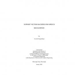
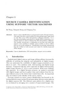
Normalization (Cheriet et al., 2007) is a process that results in regulating the size, position and shape of the segmented images of the characters so as to reduce the variation in size of the images belonging to the same class thus facilitating the extraction of features and increasing the accuracy of classification. Mainly there are two types of methods: linear and non-linear. As presented in Fig. 1, we mark by W1 and H1 the width and height of the original character, and by W2 and H 2 the width and height of the normalized character and by L the size of the standard plane. This size is considered to be, usually, 32x32 or 64x64. We define the aspect ratios of the original character ( R1 ) and that of the normalized one ( R2 ) as: R1 =
min(W1 , H1 ) max(W1 , H1 )
(3)
R2 =
min(W2 , H 2 ) max(W2 , H 2 )
(4)
which are always between [0,1].
Fig. 1 − The original character (a) ; The normalized character which fills the standard plane (b).
In the so-called “Aspect Ratio Adaptive Normalization” (ARAN), the aspect ratio of the normalized character R2 is computed adaptively based on the
Bul. Inst. Polit. Iaşi, t. LVIII (LXII), f. 2, 2012
35
original character R1 using one of the functions in Table 1. In implementing this method, normalized character image is placed over a plan with flexible sizes (W2, H2), then the plan is moved so that it is superimposed on the standard plan by aligning the center. If the image fills one dimension of the normalized standard plane, then L is considered to be equal to max(W2, H2) and the other dimension is centered in the standard plane. With R2 and L, we can calculate min(W2, H2) using the formula given above. Thus, we can obtain the size (W2, H2) of the normalized character. Table 1 Functions for Aspect Ratio Mapping Method Function Fixed aspect ration Aspect ratio preserved
R2 = 1 R2 = R1
Square root of aspect ratio
R2 = R1
Cubic root of aspect ratio
R2 = 3 R1
π
R2 = sin( R1 ) 2
Sine of aspect ratio
Coordinate transformation from the original plan on the character in the normalized one is done using forward or backward mapping. If we denote the original image, respectively, the normalized one, by f ( x, y ) and g ( x' , y ' ) , the normalized image is generated g ( x' , y ' ) = f ( x, y ) based on mapping coordinates. The forward and backward mapping are given by: x ' = x ' ( x, y ) y ' = y ' ( x, y )
(5)
x = x( x' , y ' ) y = y ( x' , y ' )
(6)
and:
In case of the forward mapping, the x and y coordinates take discrete values, but x' ( x, y ) and y ' ( x, y ) are not necessarily the same, while in the case of backward mapping the reverse is true. And furthermore, in the case of direct mapping the coordinates ( x' , y ' ) do not necessarily occupy all the space in the normalized plane. Thusly, for using the normalization we need to implement mesh coordinates and pixel interpolation. By meshing, mapped coordinates ( x' , y ' ) or ( x, y ) are approximated by the nearest integer ([ x' ],[ y ' ]) or ([ x],[ y ]) .
36
Eugen-Dumitru Tăutu and Florin Leon
In case of the mesh in the forward mapping, the discrete coordinates ( x, y ) scan the original image pixels and the pixel value f ( x, y ) is assigned to all the pixels that fall within the range ([ x' ( x, y )],[ y ' ( x, y )]) to ([ x' ( x + 1, y + 1)],[ y ' ( x + 1, y + 1)]) . The forward mapping is mostly used because of the fact that meshing the mapped coordinates ( x, y ) can be easily done. The functions for the forward and backwards mapping are given in Table 2. Denoted by α and β in the table, they are given by:
α = W2 W1 β = H 2 H1
(7)
Table 2 Functions for Coordinate Mapping Method
Forward mapping
Backwards mapping
x' = α x
x = x' α
y' = β y
y = y' β
Linear
x' = α ( x − xc ) + x 'c
Moment
y ' = β ( y − y c ) + y 'c
x ' = W2 h x ( x )
Non-linear
y ' = H 2 hy ( y)
x' =
( x '− x'c )
y' =
( y '− y 'c )
α β
x' = hx−1 (
+ xc + yc
x' ) W2
y ' = h y−1 (
y' ) H2
2.4. The Discrete Cosine Transformation
For extracting the features that define the characters in the image we used the discrete cosine transformation (Watson, 1994), which is a technique that converts a signal into its elementary frequency components. Each line of M pixels from an image can be represented as a sum of M weighted cosine functions, assessed in discrete points, as shown by the following equation (in the one-dimensional case): M −1
Ti =
∑ x=0
for 0 ≤ i < M where C x =
2C x M
s x cos
(2i + 1) xπ 2M
2 for x = 0 , otherwise C x = 1 . 2
(8)
Bul. Inst. Polit. Iaşi, t. LVIII (LXII), f. 2, 2012
37
In the bidimensional case, we consider a matrix S of 8x8 elements defined by (Petrescu, 2006): 7 7 1 (2 x + 1) jπ (2 y + 1)iπ cos Ti. j = Ci C j ∑ ∑ s y , x cos 4 16 16 x =0 y =0
In eq. (9) it is considered that Ci = C j =
1
(9)
, for i, j = 0 , otherwise
2
Ci = C j = 1 .
It can be said that the transformed matrix elements with lower indices correspond to coarser details in the image and those with higher indices to finer details. Therefore, if we analyze the matrix T obtained by processing different blocks of an image, we see that in the upper left corner of the matrix we have high values (positive or negative) and the more we explore down to the bottom right corner the values start to decline even more, tending to 0. The next step is the actual selection of certain elements in the array. The first operation that can be done is to order the elements of the matrix into an onedimensional array so as to highlight as many values of zero as possible. The ordering is done by reading the matrix in zigzag. To extract the necessary features for character recognition we can select the first N values from this array. As N increases, so does the recognition accuracy, but that happens at the expense of increasing the training time of the support vector machine. 3. System Architecture The functionalities offered by the application have been implemented in three different modules, two of which were built as a dynamic linked library (DLL), and the third one consists of the user interface which encompasses the other two along with the support vector machine module. The three modules are: − Preprocessing module − Feature extraction module − Support vector machine module For implementation the C# programming language was chosen under Visual Studio 2008 and with the version 4.0 of the .NET platform. This choice was made because C # offers the possibility of using the GDI+ library, which proves to be fast when processing an image pixel by pixel. 3.1. The Preprocessing Module
A first step through which the image passes is to convert it into an image with gray levels, after which the optimal threshold for binarization is computed by
38
Eugen-Dumitru Tăutu and Florin Leon
using the the Otsu method. With this threshold, the image is converted to black and white, thus highliting the handwritten characters which it contains. The next step is to segment the areas corresponding to the letters of the handwritten words from the image converted to black and white, after which these areas are converted to a matrix with values of 0 and 1. One last operation performed by this module is to normalize this matrix to a predetermined size so as to facilitate the feature extraction process. 3.2. Feature Extraction Module
This module was designed to extract the features from the segmented areas of the image containing the characters to be recognized, traits that serve to distinguish an area corresponding to a letter from an area corresponding to other letters. To begin with, the first n components of the discrete cosine transformation of a segmented area are considered to be the features that describe it. In the next phase, certain statistical details of the area are added to the discrete consine transformation components to define its features: − number of black pixels from a matrix (the so called “on”" pixels); − mean of the horizontal positions of all the "on" pixels relative to the centre of the image and to it's width; − mean of the vertical positions of all the "on" pixels relative to the centre of the image and to it's height; − mean of horizontal distances between "on" pixels; − mean of vertical distances between "on" pixels; − mean product between vertical and horizontal distances of "on" pixels; − mean product between the square of horizontal and vertical distances between all "on" pixels; − mean product between the square of vertical and horizontal distances between all "on" pixels; − mean number of margins met by scanning the image from left to right; − sum of vertical positons of the margins met by scanning the image from left to right; − mean number of margins met by scanning the image from bottom to top; − sum of horizontal positions of the margins met by scanning the image from top to bottom. One last operation implemented by this module is the normalization of the results obtained up until now so as they corespond to the format accepted by the support vector machine module. 3.3. Support Vector Machine Module
The module offers the possibility of selecting different types of kernel functions, such as the sigmoid, RBF, linear functions, and the setting of the
39
Bul. Inst. Polit. Iaşi, t. LVIII (LXII), f. 2, 2012
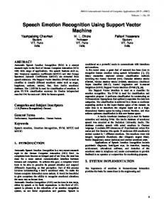
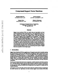
various parameters of these kernels (Hsu et al., 2010). After setting the type of kernel and its parameters, the support vector machine is trained with the set of features given by the other modules. Once the training is over, the support vector machine can be used to classify new sets of characters. For building this module, we used the SVM.NET library (Johnson, 2009) which is an implementation of the libSVM library (Chang & Lin, 2012) for the .NET platform. 4. Experimental Results For testing the accuracy of the system, we used, in a first test scenario, an image which contained 100 small letters only (Fig. 2). The construction of the training set, which consisted of two images containing 40 examples of each small letter in the English alphabet, took 18.5058 sec. The results are presented in Table 3.
Fig. 2 − Test image used for small letters. Table 3 Results for Training with Sets that Correspond only to Small Letters Kernel function Linear Linear Linear RBF RBF RBF RBF RBF RBF RBF RBF Polynomial Polynomial Polynomial Polynomial Polynomial
C
p
1 10 100 10 10 10 10 10 10 10 10 10 10 10 10 10
− − − − − − − − − − − 2 2 2 2 3
Precision − − − − − − − − − − − 2 4 1 0.5 2
− − − 0.25 0.15 0.1 0.05 0.03 0.02 0.01 0.005 − − − − −
− − − − − − − − − − − − − − − −
88% 86% 86% 91% 91% 92% 93% 92% 95% 96% 95% 93% 80% 88% 87% 92%
40
Eugen-Dumitru Tăutu and Florin Leon
Table 3 Continuation Kernel function
C
p
Polynomial Polynomial Polynomial Polynomial Polynomial Polynomial Polynomial Sigmoid Sigmoid Sigmoid Sigmoid
10 10 10 10 10 10 10 10 10 10 10
3 3 3 4 4 4 4 − − − −
Precision 4 1 0.5 2 4 1 0.5 0.5 0.5 0.2 0.7
− − − − − − − − − − −
− − − − − − 1 5 1 1
80% 88% 87% 92% 82% 88% 87% 93% 83% 66% 49%
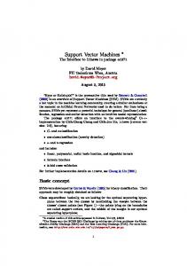
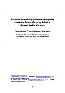
For the next test scenario we used for training only the features corresponding to capital letters. The image used for testing contained 100 letters, and the construction of the training set, which consisted of two images containing 40 examples of each capital letter in the English alphabet, took 19.5075 sec. The results are presented in Table 4.
Fig. 3 − Test image used for capital letters. Table 4 Results for Training with Sets that Correspond only to Capital Letters Kernel function Linear Linear Linear RBF RBF RBF RBF RBF
C
p
1 10 100 10 10 10 10 10
− − − − − − − −
Precision − − − − − − − −
− − − 0.25 0.15 0.1 0.05 0.03
− − − − − − − −
87% 88% 86% 90% 89% 93% 92% 89%
41
Bul. Inst. Polit. Iaşi, t. LVIII (LXII), f. 2, 2012
Table 4 Continuation Kernel function
C
p
Precision
RBF RBF RBF Polynomial Polynomial Polynomial Polynomial Polynomial Polynomial Polynomial Polynomial Polynomial Polynomial Polynomial Polynomial Sigmoid Sigmoid
10 10 10 10 10 10 10 10 10 10 10 10 10 10 10 10 10
− − − 2 2 2 2 3 3 3 3 4 4 4 4 − −
− − − 2 4 1 0.5 2 4 1 0.5 2 4 1 0.5 0.5 0.2
0.02 0.01 0.005 − − − − − − − − − − − − − −
− − − − − − − − − − − − − − − 1 1
89% 88% 90% 93% 75% 93% 92% 93% 71% 95% 91% 94% 71% 92% 91% 47% 66%
The last test cases consisted of training the support vector machine with sets corresponding to both small and capital letters. The images used for testing were the previous ones, and the construction of the training set took 37.9334 seconds. The results are presented in Table 5. Table 5 Results for Training with Sets Corresponding to Both Small and Capital Letters Kernel function Linear Linear RBF RBF RBF RBF Polynomial Polynomial Polynomial Sigmoid Sigmoid
C
p
1 10 10 10 10 10 10 10 10 10 10
− − − − − − 2 3 4 − −
Precision − − − − − − 2 2 2 0.5 0.2
− − 0.25 0.1 0.05 0.01 − − − − −
− − − − − − − − − 1 1
79% 74.5% 76.5% 79% 80% 76.5% 74% 71% 71% 47% 50%
The tests were conducted on a AMD Athlox X3 460 at 3.4 GHz frequency, with 4 GB RAM. During the construction of the training set (the
42
Eugen-Dumitru Tăutu and Florin Leon
lengthiest operation of the system), the processor was loaded to 33% and the application occupied 55.120 MB of memory. During idle mode, the application consumes 44.892 MB of memory. 6. Conclusions The system uses in its implementation methods like the Otsu technique for calculating the global threshold of an image that is later used on its binarization. Following that, an own algorithm for segmenting characters from the image is used, after which the areas determined by this algorithm are transformed and normalized so that they have the same dimensions in order to facilitate the feature extraction process. The features extracted from the area include components of the discrete cosine transformation applied to images and some statistics details of it. One last step before sending these features to the support vector machine is to scale them to a range accepted by it. Reaching a precision rate of 90% in case of training with sets corresponding to small or capital letters, and one of over 75% in case of training the support vector machine with sets of both small and capital letters, the system achieved its goal which is the recognition of characters from an image. A future direction of expanding the system would be the addition of techniques that determine automatically the optimal parameters of the kernel functions. Also, an own implementation of the support vector machine module can be added further on.
REFERENCES Agell
C., Neural Networks for Pen Characters Recognition. (online) http://www.ics.uci.edu/~dramanan/teaching/ics273a_winter08/projects/cagell_ AgellProject.pdf, 2008. Chang C.C., Lin C. J., LIBSVM – A Library for Support Vector Machines. (online) http://www.csie.ntu.edu.tw/~cjlin/libsvm/, 2012. Cheriet M., Kharma N., Liu C-L, Ching Y.S., Character Recognition Systems. John Wiley & Sons, Inc., 2007. Hsu C-W, Chang C-C, Lin C-J, A Practical Guide to Support Vector Classification. (online) http://www.csie.ntu.edu.tw/~cjlin/papers/guide/guide.pdf, 2010. Johnson M., SVM.NET. (online) http://www.matthewajohnson.org/software/svm.html, 2009 Liu C-L, Sako H., Fujisawa H., Performance Evaluation of Pattern Classifiers for Handwritten Character Recognition. International Journal on Document Analysis and Recognition, 4, 191−204, 2002. Otsu N., A threshold selection method from gray-level histograms, IEEE Trans. Sys., Man., Cyber. 9, 1, 62–66, 1979. Petrescu C., Compresia imaginilor. (online) http://www.indinf.pub.ro/catalinp/img/img.htm, 2006.
Bul. Inst. Polit. Iaşi, t. LVIII (LXII), f. 2, 2012
43
Sandu V., Leon F., Recognition of Hadwritten Digits Using Multilayer Perceptrons. Bul. Inst. Polit. Iaşi, s. Automatic Control and Computer Science, LV (LIX), 4, 103−114, 2009. Watson B.A., Image Compression Using the Discrete Cosine Transform. Mathematica Journal, 4, 1, 81−88, 1994.
SISTEM DE RECUNOAŞTERE A SCRISULUI DE MÂNĂ FOLOSIND MAŞINI CU VECTORI SUPORT (Rezumat) Lucrarea de faŃă prezintă un sistem de recunoaştere a scrisului de mână dintr-o imagine. Implementarea sistemului include într-o primă fază operaŃii de convertire a imaginilor color în alb-negru, lucru realizat mai întâi printr-o convertire a imaginii color într-o imagine cu nivele de gri, pentru ca mai apoi aceasta să fie binarizată folosind metoda Otsu. Pentru următoarea operaŃie, şi anume cea de segmentarea a zonelor de interes, s-a dezvoltat un algoritm propriu prin care pornindu-se de la o zonă iniŃială de un pixel, se ajunge la o zonă care include toŃi pixelii ce alcătuiesc caracterul scris de mână prin expandarea zonei iniŃiale în trei direcŃii: sus, stânga şi dreapta. Următorul pas este de a converti zonele extrase în matrici cu valori de 0 şi 1, pentru ca mai apoi acestea să fie aduse la o mărime predefinită, şi anume de 24x24 prin folosirea tehnicii de normalizare adaptivă a raportului de aspect. O ultimă operaŃie realizată este dată de extragerea de trăsături, lucru realizat prin implementarea transformatei cosinus discrete, precum şi extragerea de anumite detalii statistice ale zonei în cauză. Pentru recunoaşterea caracterelor s-a folosit biblioteca SVM.NET, ce implementează operaŃiile necesare construirii unei maşini cu vectori suport. Din cazurile de test considerate, reiese faptul că sistemul atinge un grad de precizie ridicat şi un timp de execuŃie redus.