BMW additionally has introduced an ... polymer optical fibers (POF) as
waveguides, red emitting LEDs, and ... as the maintenance and repair concept of
the cars cable harness in ... PMMA POF, cables with 200 µm PCS fibers provide
twice the ...
Optical Communication Systems for Automobiles Torsten Schaal, Thomas Kibler, and Eberhard Zeeb DaimlerChrysler AG, Wilhelm-Runge-Str. 11, 89081 Ulm, Germany email:
[email protected] Abstract In this paper an overview of currently used optoelectronic communication systems in automobiles is given and future applications as well as technological challenges are discussed.
Introduction Optoelectronic systems are more and more attractive to communicate both inside and outside cars. While for in-car systems the main driving factor to introduce optical systems is the need for high bandwidth channels without electromagnetic interference, free space car-to-car communication systems have the potential to enhance the active and passive driving safety. Here we give an overview of fiber based optical data bus systems for in-car networks, as well as free space communication systems for car-to-car communication, using standard LED lighting elements. Optical Data Bus Systems In 1998 the digital domestic bus (D²B) was introduced as the first optical data bus system [1] in MercedesBenz cars for an infotainment system. The system data rate of 5.6 Mbps is capable to transmit speech, audio, and control data for phones, mobiles, sound systems, and speech recognition systems arranged in a ring. In 2001 an international consortium of car manufactures and suppliers set up an open standard for infotainment networks, the media oriented system transport (MOST) [2]. The data rate of the MOST ring network with 22.5 Mbps allows the transmission of compressed video data. Until now MOST is introduced in more than 20 series car models of different manufactures and over six million nodes are on the road. It is estimated that over 10 million nodes will be sold per year from 2005 on. BMW additionally has introduced an optical data bus system for an airbag sensor network, the so-called Byteflight system [3]. Here all network participants are connected by point-to-point links to an intelligent central star coupler. All currently installed optical data bus systems in cars, D²B, MOST, and Byteflight, use basically the same optical and optoelectronic components: polymethyl methacrylate (PMMA) polymer optical fibers (POF) as waveguides, red emitting LEDs, and large areas silicon photoreceivers. POFs were chosen as waveguides because they are more flexible than silica fibers, allowing the realization of large and still flexible core diameter fibers (e.g. 1 mm). The main advantage of POFs are the relaxed connector tolerances due to the large core diameter and the easy and efficient coupling of high NA light
sources to the fiber. This simplifies the connector design and allows the use of plastic injection-molded components, even for ferrules. As transmission wavelength the 650 nm low loss window of PMMA POF is used, because in this wavelength region low-cost red light emitting diodes and efficient silicon photodiodes are available. Device characteristics of typical transmitters and receivers used in the MOST data bus system are shown in Table 1. Due to device fabrication tolerances and to the required wide temperature range the output power of the LEDs within an acceptance angle of a 0.5 NA fiber is between -1.5 dBm and -10 dBm and the peak wavelength of the LEDs varies between 630 nm and 685 nm. The sensitivity of large area (1mm diameter) silicon photodetectors is about –23 dBm with an overload limit of –2 dBm. These device parameters allow car manufacturers to use a power budget of 13 dB for its cabling harness between two network nodes. Table 1: Specified data of MOST transmitter and receiver modules [4] under automotive worst case conditions. parameter value transmitter peak wavelength
630 ... 685 nm
spectral width output power
≤ 30 nm -1.5 ... –10 dBm
rise/fall time
8 ns
receiver sensitivity
-23 dBm
overload
-2 dBm
Due to the relatively high effective attenuation of the fiber of about 0.4 dB/m (caused by the broad LED emission spectrum and the emission wavelength which is not exactly 650 nm) and the connector insertion losses of approx. 2 dB today only point-topoint links are realized both in the ring topology of the D2B or MOST systems as well as in the active star configuration of the ByteFlight bus. For example a point-to-point link with a length of 15 m and two connectors at the interfaces of the connected devices already has a worst case attenuation of 10 dB, leaving a 3 dB margin for additional inline connectors, bending or installation losses, and a system margin. This margin hardly allows the insertion of additional
in-line connectors or other passive coupling elements. A second limitation of PMMA fiber based networks is the maximum ambient temperature range of about 85 °C, so that they can only be used in the passenger compartment of the car and not in the roof or in the engine compartment. Last but no least the bandwidth of PMMA fiber systems can not be enhanced easily to data rates well above 100 MBps, due to the limited bandwidth of the fiber, of the LED as well as of large area photodetectors. For future automotive optical data links is necessary to have optical wiring solutions with higher power budget and optical wires, which would allow lower bending radii, simpler handling procedures and higher ambient temperatures. This would dramatically simplify the harness pre-fabrication process at the supplier side, the final installation and car manufacturing process at the assembly lines, as well as the maintenance and repair concept of the cars cable harness in the workshops. In addition new kind of high speed data transmission networks will be needed in cars for novel applications. Examples are sensor systems for safety applications, engine management systems, drive-by-wire systems, and video processing systems for driver assistance and autonomous driving [5]. For these applications today’s optical data bus technologies and systems reach their limits mainly in terms of temperature stability, required power budget and allowed data rates. Therefore new physical layer solutions have to be found. To overcome all above mentioned limitations of the PMMA physical layer, we have proposed a new physical layer concept based on polymer clad large core silica fibers (PCS) fibers and 850 nm emitting vertical-cavity surface-emitting lasers (VCSELs). Using these components the fiber attenuation of about 0.006 dB/m can be neglected for typical link lengths in cars and the fiber can be used up to ambient temperatures of at least 125 °C. For optical data links a fiber core diameter of 200 µm is a good compromise between fiber flexibility and a sufficient large core diameter for efficient coupling to active components and acceptable connector alignment tolerances. Compared to cables with 1 mm diameter PMMA POF, cables with 200 µm PCS fibers provide twice the short-term tensile strength, one-third the minimum bend radius and up to ten times greater long-term tensile strength and flexing capability. Minimum bending radii of standard PCS fibers are 10 mm short term and 16 mm long term [6] and even can be reduced by higher proof test levels during fiber drawing. In a series of tests we have investigated the reliability of several PCS cables under the most important environmental impacts, temperature and mechanical bendings. The tests have shown their principle feasibility for automotive applications [7].
The low loss of PCS fibers at 850 nm opens the possibility to use GaAs vertical-cavity surface-emitting lasers (VCSELs) [8] as transmitters. These lasers are widely used in datacom applications and are very attractive to be used in the automotive environment. The device has a large modulation bandwidth (>1 Gbps), a low threshold current, a high efficiency, and can be driven with simple driving circuits. Reliability studies and their use in large quantities in the datacom market have shown lifetimes of several ten thousand hours even at high temperatures up to 125 °C [9]. As first demonstration of the feasibility of a PCS/VCSEL physical layer for automotive application we have build up several MOST networks based on this new technology. We have replaced the optoelectronic LED-transmitter and receiver modules in standard series entertainment and have used PCS cables in the cable harness. To make an easy replacement possible, the pinning and the outer dimension of the transceiver packages were firstly kept unchanged. Table 2 shows a comparison of the power budget for the PMMA/LED and the VCSEL/PCS solution. Changing only the transmitter and the fiber an increase of the point-to-point link budget of 7 dB is achieved and at the same time the fiber attenuation vanishes. Connector losses for both systems are about the same. Table 2: Power Budget Comparison of PMMA/LED and PCS/VCSEL MOST System Parameter PMMA/LED PCS/VCSEL system system Max. optical output power -1.5 dBm -1.5 dBm Min. optical output power -10 dBm -5 dBm Min. receivable power -23 dBm -25 dBm Dynamic range 13 dB 20 dB Fiber transmission loss 0.4 dB/m < 0.01 dB/m In-line connector loss 2 dB < 2 dB Header connector loss 2.5 dB < 2.5 dB
Using the PCS/VCSEL physical layer, cable harness designer no longer have to consider restrictions due to power budget or temperature range limitations. More than 5 in-line connectors independent of the link length between two devices can be used to simplify the harness installation, narrow bending radii are allowed, and the cable can be installed in all installation areas, even in the engine compartment or in hot areas close to the air condition system. Using the same low-cost components the data rate of the optical network can be enhanced, even into the GBps range without adding costs. Therefore we think that this new type of optical physical layer has the strong potential to be the basis of a common and scalable physical layer of high speed data links in a car. A first project to bring PCS fibers and VCSELs into series cars has been started in our company.
Figure 1: Principle of optical free space car-to-car communication.
day (3000 lx)
-10 night (150 lx)
-20
Imax= 260 cd (stop light)
-30
dynamic range
-40 -50 -60
Imin = 8 cd (rear light) 20
40
60
80
distance [m]
100 120 140
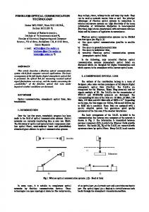
Figure 2: Ambient light irradiance (day/night) behind the spectral filter in comparison with the signal irradiance.
We realized ambient light rejection by an active feedback loop instead of a conventional passive RC network. The voltage across the photodiode is constant and the overall receiver bandwidth independent of the ambient light levels. To increase the input dynamic range of the receiver we investigated two approaches: input current shunting (X-AMP [13]) or a logarithmic amplifier. Measurement results of both receiver concepts are shown in Fig. 3. Both show comparable characteristics. The ambient light rejection is better than 30 dB, the possible communication distance is 85 m at day and 130 m at night.
ambient light [lx] -36
150
-37
500
1000
3000 80 90
night
-38
Log-Amp X-Amp
-39 -40
day
-41 -42 -22
-19
-16
-13
-10
100 110 120
distance [m]
In contrast to radio communication techniques optical free space communication systems require line of sight and the possible transmission distance is influenced e.g. by bad weather condition. However speed and distance have to be adapted to the visibility condition anyway, regulated by law. Therefore this could even be considered as an advantage. Worst case conditions for practical optical free space communication systems are sunny days resulting in high ambient light. This is shown in Fig. 2 where radiant power of ambient light at day and night time is compared with the signal irradiance of a typical LED rear light. The irradiance of the ambient light is independent of the distance. The values depicted in the viewgraphs are valid for a photodiode with a spectral filter (FWHM = 50 nm) which the reduces the ambient light intensity by 12 dB. The
0
radiant power [dBm]
Several approaches to establish car-to-car communication are currently under investigation. The main focus is on radio communication techniques. Such solutions need special transmitting elements installed at the car. A very attractive alternative could be the use of LEDs as transmitters for data communications which are already installed as rear lights (see Fig. 1). Thus no extra installation space is needed, leading to a reduction of cost and weight. Additionally the radiant exposure by electromagnetic pollution is reduced to a minimum. Measurements show, that LEDs, which are originally designed only for lighting purposes, have enough modulation bandwidth to support data transmission in the MBps range [12].
irradiance of the signal decreases with the square of the distance and the received optical signal power varies between 5 decades for a distance up to 100 m. Therefore the receiver requires a large dynamic range, high sensitivity and an efficient suppression of the ambient light.
sensitivity [dBm]
Car-to-car communication A big step towards the goal of “accident free driving” is to establish data communication between cars, to exchange relevant information (e.g. deceleration, velocity, street condition, ESP information, steering angle). This data could be used to warn the driver with optic or acoustic signals or in a next step to support autonomous driving functions. E.g. an emergency braking could be signalized to the followup traffic by data communication so that the driver’s reaction time, which is approximately 1 s [10], can be eliminated. The required data rate to transmit all relevant information can be estimated to about 400 kBps[11].
130 140 -7
ambient light [dBm] Figure 3: Receiver sensitivity in [dBm] as a function of the ambient light level.
When a photodiode array instead of a single element is used a separation between cars e.g. on parallel lanes is possible. The basic concept for such a system is shown in Fig. 4. We use two receiver units for higher resolution and redundancy which are mounted within the left and right head lamp. The rear lights of cars in front are focussed on different array elements allowing separation and distance approximation by geometrical triangulation. Using a 16 elements photodiode array with an element size of 0.7 mm x 2.0 mm a separation between cars up to a distance of 130 m is possible. Car B
Car A Car B Car C
Car A Optic right Photodiode Array 16x right. Photodiode Array 16x left Optic left x
distance d
z
Figure 4: Principle to separate between cars on several parallel lanes by using a suitable photodiode array.
Conclusion Optoelectronic systems are increasingly used for communication applications in cars. After the successful introduction of PMMA based fiber links we have shown in the lab as well as in test cars the suitability of PCS and VCSEL based optical data bus systems for next generation high speed car networks. First activities have been started together with key component suppliers to establish PCS/VCSEL networks. Beside in-car networks we demonstrated free space car-to-car communication to enhance the driving safety by transmitting traffic relevant information, like e.g. speed, deceleration, and ESP data. We have realized a data rate of 1 MBps over a distance of up to 130 m using standard LED rear lights. Standardization of car-to-car communication is necessary to establish the system on the market and to achieve full benefits of this approach to reach the goal of accident free driving.
References 1 D. Seidl, P. Merget, J. Schneider, R. Weniger, and E. Zeeb, “Applications of POFs in data links of mobile systems,” in Proc. 7th Int. Polymer Optical Fiber (POF) Conference, pp. 205-211, Berlin, October 1998. 2 MOST Cooperation official web site, http://www.mostcooperation.com. 3 Byteflight official web site, http://www.byteflight.com. 4 MOST Specification of Physical layer, rev. 1.1, Sept. 2003, pp. 19-21. 5 E. Zeeb, “ Optical Data Bus Systems in Cars: Current Status and Future Challenges,” ECOC 2001, vol. 1, pp. 70-71, Amsterdam, 2001. 6 OFS, HCS Product Line. Available: http://www.fiber-wire.com. 7 T. Kibler, S. Poferl, G. Böck, H.-P. Huber, and E. Zeeb, “Optical data Buses For Automotive Applications,” IEEE J. Lightwave Techn., submitted for publication. 8 M.H. Crawford, W.W. Chow, K.D. Choquette and K.L. Lear, “Design, fabrication and performance of infrared and visible vertical-cavity surface-emitting lasers,” in IEEE Journal of Quantum Electronics, vol. 33, no. 10, pp. 1810-1824, 1997. 9 M. Hawkins, R. A. Hawthorne III, J. K. Guenter, J. A. Tatum, and J. R: Biard, “ Reliability of Various Size Oxide Aperture VCSELs,” in Conference Proc. ECTC 2002, pp. 540-550, San Diego, May 2002. 10 P. Rieth and T. Eberz. Reduction of Stopping Distance Through Chassis System Networking, Convergence 2002 Proceedings, Detroit, 2002 11 T.Schaal and E. Zeeb: Empfängerarrays für die optische Datenkommunikation zwischen Kraftfahrzeugen; Haus der Technik, Konferenz Elektronik im Kraftfahrzeug, Essen, 2004 12 T.Schaal and E.Zeeb: Optical Free Space Communication with LED Rear Lights. 5th International Symposium Progress in Automobile Lighting, Proc. PAL2003, pp.942-954, Darmstadt, 2003 13 Analog Devices, AD603 X-AMP, Datasheet