JOURNAL OF LIGHTWAVE TECHNOLOGY, VOL. 26, NO. 15, AUGUST 1, 2008
2513
Optical Generation of Binary Phase-Coded Direct-Sequence UWB Signals Using a Multichannel Chirped Fiber Bragg Grating Yitang Dai and Jianping Yao, Senior Member, IEEE, Member, OSA
Abstract—A novel technique to generate binary phase-coded, direct-sequence ultra-wideband (DS-UWB) signals in the optical domain is proposed and demonstrated. In the proposed system, the wavelengths from a laser array are modulated by a Gaussian pulse, which is sent to a multichannel optical frequency discriminator, to generate a UWB monocycle or doublet pulse sequence with a predetermined phase-code pattern. By tuning the wavelengths of the laser array, or by tuning the states of polarization of the wavelengths, the generated pulse shape and code pattern can be changed. The key device in the system is the multichannel dispersive chirped fiber Bragg grating (FBG), which functions, in combination with a dispersive fiber, as a multichannel frequency discriminator with a step-increased group-delay response, to ensure the generated UWB sequence to have uniform time spacing among the chips and to compensate for the fiber-induced chromatic dispersion. The proposed scheme is experimentally demonstrated. A multichannel chirped FBG is designed and fabricated. Binary phase-coded DS-UWB signals with different code patterns are experimentally generated. Index Terms—Direct sequence (DS), fiber Bragg grating (FBG), phase coding, ultra-wideband (UWB).
I. INTRODUCTION
ECENTLY, the generation and distribution of ultra-wideband (UWB) signals in the optical domain, to take advantage of the low loss and broad bandwidth offered by optics, has been a topic of interest. UWB, approved in February 2002 by the U.S. Federal Communications Commission (FCC) for unlicensed use in a frequency band from 3.1 to 10.6 GHz, has been considered a promising technology for short-range high-data-rate wireless communications and sensor networks. There are, in general, two types of UWB: the multiband UWB and the direct-sequence UWB (DS-UWB). DS-UWB is one of the most attractive techniques for UWB communications since it is carrier free; therefore, there is no need for complicated frequency mixers and local oscillators to down- or upconvert the carrier frequency. In a DS-UWB system, information is
R
Manuscript received January 28, 2008; revised May 6, 2008. Current version published October 10, 2008. The work was supported by the Natural Sciences and Engineering Research Council of Canada (NSERC). The authors are with the Microwave Photonics Research Laboratory, School of Information Technology and Engineering, University of Ottawa, Ottawa, ON K1N 6N5, Canada (e-mail:
[email protected]). Color versions of one or more of the figures in this paper are available online at http://ieeexplore.ieee.org. Digital Object Identifier 10.1109/JLT.2008.927207
represented by coded narrow pulses (in the order of a fraction of a nanosecond) with very small duty cycle. Compared with the conventional wireless communications technologies, UWB has distinct advantages, such as immunity to multipath fading, extremely short time duration, carrier free, low duty cycle, wide bandwidth, and low power spectral density [1], [2]. In the past, most of the efforts were focused on the generation of UWB pulses to ensure that the power spectrum of the pulses satisfies the FCC-specified spectral mask. For wireless communications and sensor networks, to support multiple -user communications, the UWB pulses should be encoded [3]. The direct-sequence code-division multiple-access (DS-CDMA) technique has been widely used in modern wireless communications systems to support multiple-user communications. In a DS-CDMA system, the users share a common frequency band, but the signals are distinguishable from each other since each user is assigned a specific orthogonal code, which can be detectable at a receiver by matched filtering. The same concept can be applied to an impulse UWB communications system to support multiple-user communications [4]. On the other hand, due to the low-power density regulated by the FCC, the UWB communication distance is limited to a few to tens of meters. Such a short-range wireless network can operate mainly in indoor environments in a stand-alone mode, with a nearly nonexistent integration into the fixed wired networks or wireless wide-area infrastructures. New technologies are highly desirable to offer availability of undisrupted service across different networks and eventually achieve high-data-rate access at any time and from any place. The convergence of optical and UWB technologies, to distribute UWB signals over fiber, or UWB over fiber, would be a promising solution. In addition, the generation of UWB pulses in the electronic domain is rather expensive and difficult, especially for UWB pulses with a fractional bandwidth greater than 100% [5]–[7]. Optical signal processing technology has been well developed currently. The generation and processing of UWB signals in the optical domain can benefit from the huge bandwidth offered by optics. As a result, UWB-over-fiber technology has been a topic of interest recently [8]–[17]. Among the techniques proposed recently, only UWB pulse generation has been intensively investigated. For a communication network that supports multiple-user communications, the impulse UWB pulses must be encoded with one user having a specific code, the encoded multiuser signals are distributed via optical fiber to the base stations and radiate to free space. At a UWB receiver, the specific code would be decoded through matched filtering.
0733-8724/$25.00 © 2008 IEEE Authorized licensed use limited to: University of Ottawa. Downloaded on November 22, 2008 at 13:14 from IEEE Xplore. Restrictions apply.
2514
JOURNAL OF LIGHTWAVE TECHNOLOGY, VOL. 26, NO. 15, AUGUST 1, 2008
We have recently proposed and demonstrated an approach to optical generation of binary phase-coded DS-UWB signals [18]. In the proposed approach, a fiber Bragg grating (FBG) array was used as a multichannel frequency discriminator, to perform phase modulation to intensity modulation (PM-IM) conversion, leading to the generation of a bipolar UWB code. The temporal separation of the code chips is dependent on the physical separation of the FBGs in the array. The desired bipolar code pattern is obtained by locating the optical carriers at the left or right slopes of the FBG reflection spectra. The major limitation of the approach is that the FBGs with different Bragg wavelengths in the array were fabricated in a fiber. The FBGs are physically separated with identical spacing, which leads to the FBG array to have a long length when the code pattern has many chips, and the system will be bulky with low stability. In addition, the spectral uniformity of the long FBG array is hard to control since the writing process involves multiple FBGs with multiple phase masks. To avoid using an FBG array, we have recently demonstrated a technique to use a multichannel chirped FBG for UWB pulse encoding [19]. A proof-of-concept experiment was performed. To have a better understanding of the technique, especially the design and the fabrication of the multichannel chirped FBG, we believe that an in-depth theoretical analysis with experimental verifications is necessary. In this paper, we perform a detailed study of the technique using a multichannel chirped FBG to generate and distribute binary phase-coded DS-UWB signals for multiple access communications. The key device in the system is the multichannel chirped FBG, which is designed based on the spectral Talbot effect [20], [21] and has a high-channel-count multichannel dispersion response with good spectrum uniformity. The use of the multichannel chirped FBG to generate binary phase-coded monocycle and doublet sequences are experimentally demonstrated. The remainder of the paper is organized as follows. In Section II, the principle of the proposed UWB coding technique is discussed. The design and fabrication of the multichannel chirped FBG is presented in Section III. The experimental results are presented in Section IV. Four-chip binary phase coded monocycle and doublet sequences with different code patterns are experimentally demonstrated. In Section V, an alternative architecture that uses a polarization modulator (PolM) to replace the phase modulator to achieve tunable UWB code generation using fixed optical wavelengths is proposed and investigated. A conclusion is drawn in Section VI. II. PRINCIPLE Many approaches have been proposed and demonstrated for the optical generation of UWB pulses. Generally, Gaussian monocycle or doublet pulses, which are considered excellent pulse candidates for UWB communications, can be generated by implementing the first- or the second-order derivative of a Gaussian pulse [12]. A simple technique to perform the first- or the second-order derivative is to implement phase modulation in a phase modulator and PM-IM conversion in a first- or a second-order frequency discriminator [13] to generate a UWB monocycle or doublet if the input pulse is a standard Gaussian pulse. The frequency discriminator could be an FBG or an
Fig. 1. Proposed UWB coding system. PM: Phase modulator; PD: photodetector; FBG: fiber Bragg grating.
optical filter with a spectral response having linear or quadratic spectral slopes [13]. By locating the phase-modulated optical carrier at the linear or the quadratic slope of the FBG reflection spectrum, a Gaussian monocycle or doublet pulse would be generated. The polarity of the UWB pulses can be switched if the location of the optical carrier is switched between the left or right slope of the FBG reflection spectrum. A theoretical analysis on an FBG-based frequency discriminator has been presented in [16], in which the FBG was used as a first- or a second-order frequency differentiator. Being similar to the conventional DS-CDMA encoding scheme, a binary phase-coded DS-UWB sequence is a UWB sequence multiplied by a pseudorandom sequence. In this paper, the UWB sequence is generated based on optical phase modulation and PM–IM conversion. For a phase-coded UWB wavesignal with a chip length of , a light source with wavelengths are phase modulated lengths are required. The by a Gaussian pulse train. The phase encoding is realized by using a multichannel chirped FBG which acts as a multichannel frequency discriminator. When the phase-modulated optical carriers are reflected by the multichannel chirped FBG, depending on the locations of the carriers at the left or right slopes of the FBG reflection spectra, a binary phase-coded UWB sequence is generated. The proposed system is shown wavelengths in Fig. 1. The output from the laser array with is phase modulated by a phase modulator, which is then sent to a specially designed, multichannel chirped FBG. To ensure that the optical carrier at the left or right slope of the reflection spectrum of a specific FBG have identical time delays, the group-delay response within the spectrum of a specific FBG must be controlled to be a constant. This is achieved in this paper by connecting the multichannel chirped FBG with a length of dispersive fiber that has an opposite dispersion, leading to a step-increased group-delay response, as shown in Fig. 2. The encoded UWB signal is then sent optically to the base station, which is converted to an electrical signal by a photodetector and radiated to free space via a UWB antenna. As shown in Fig. 2(a), by locating the wavelength of the optical carriers at the left or right, linear or quadratic slopes of the FBG reflection spectral response, a UWB code with the desired shape and phase pattern is generated. It should be noted, however, to generate a UWB sequence with identical time-delay difference between adjacent UWB pulses, a step-increased group-
Authorized licensed use limited to: University of Ottawa. Downloaded on November 22, 2008 at 13:14 from IEEE Xplore. Restrictions apply.
DAI AND YAO: OPTICAL GENERATION OF BINARY PHASE-CODED DS-UWB SIGNALS USING A MULTICHANNEL CHIRPED FBG
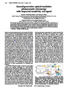
Fig. 2. Principle of the proposed UWB phase coding scheme. (a) Frequency response of the multichannel frequency discriminator. UWB pulses with different shapes and phases are generated when the optical carriers are located at the linear or quadratic, left or right slopes of the multiple reflection bands. A UWB sequence with identical temporal chip spacing is ensured by the step-increased group-delay response of the discriminator. (b) Step-increased group-delay response is generated by a multichannel chirped FBG in combination with a length of dispersive fiber.
2515
Fig. 4. (a) Calculated reflectivity and group-delay responses of the largely chirped sampled FBG with the structure illustrated in Fig. 3. (b) Group-delay response of the FBG connected with 25-km standard single-mode fiber.
Fig. 5. Measured reflectivity and the group delay of the fabricated multichannel chirped FBG. Fig. 3. Index modulation (solid line) and the Bragg wavelength distribution (i.e., the chirp; the dotted line) of the proposed multichannel FBG.
as shown in Fig. 2(b). The group-delay difference between adjacent channels is then delay response is required. Although a dispersive fiber can be used to generate different time delays for different wavelengths, it will generate unequally spaced time delays because the wavelengths are nonuniformly spaced, as can be seen from Fig. 2(a). To maintain an identical time delay for an optical carrier at either the left or right slope of a specific FBG reflection spectrum, the group delay should be maintained unchanged, as shown as the dotted line in Fig. 2(a). The step-increased group-delay response can be generated using a specially designed FBG with a multiband dispersion response in combination with a dispersive fiber, as shown in Fig. 2(b). It is known that a multiband chirped FBG has a linear dispersion within each band, but with no [22] or small [20] group-delay difference between the channels. Therefore, if the chirped FBG is connected with a dispersive fiber to cancel the in-channel dispersion of the FBG, a multichannel frequency discriminator with a step-increased group delay would be achieved,
(1) where is the channel spacing of the FBG and is the dispersion of the dispersive fiber. To compensate for the in-channel dispersion, the in-channel dispersion of the FBG should have an . opposite dispersion III. GRATING DESIGN The multichannel chirped FBG is designed based on the spectral Talbot effect [20], in which the desired FBG is a sampled FBG fabricated using a phase mask with a large chirp. This approach has the advantage that the desired large multichannel dispersion response could be easily achieved by a commercial phase mask with a large chirp rate, and the in-channel dispersion could be designed to have different values using the same
Authorized licensed use limited to: University of Ottawa. Downloaded on November 22, 2008 at 13:14 from IEEE Xplore. Restrictions apply.
2516
JOURNAL OF LIGHTWAVE TECHNOLOGY, VOL. 26, NO. 15, AUGUST 1, 2008
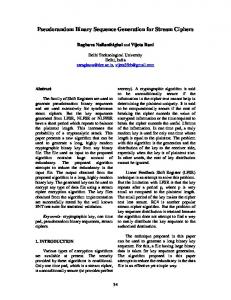
Fig. 6. Phase-coded monocycle (left) and doublet (right) sequences corresponding to different code patterns measured in the time domain.
phase mask by changing the sampling period, a technique that is different from other techniques where the dispersion is determined by the mask only [21]. The multichannel chirped FBG based on the Talbot effect has been investigated in [20] and [21]. For optical fiber communications applications, the multichannel responses should be designed to have spectral responses with flat tops and steep slopes. In the proposed UWB encoding system, however, the FBG should have multichannel spectral responses with linear and quadratic slopes. A flat top is not required. As a result, the phase shifts in [20], which are required in order to get a flat-top spectral response, are not needed here. Therefore, the grating is greatly simplified to be a largely-chirped FBG with uniform sampling. Based on [20], the sampling period of the sampled FBG is
(2) where is the grating period, is the chirp rate of the phase is the chirp rate corresponding to the induced mask, and
in-channel dispersion . The relationship between is well known and can be described as [23]
and
(3) where is the light velocity in vacuum. In our design, 532.65 nm, 0.82 nm/cm, 0.075 nm/cm, which cor425 ps/nm (equivalent to the responds to a dispersion of dispersion of about 25-km standard single mode fiber), then the 1.95 mm. In addition, in our approach sampling period the FBG with a Gaussian spectral response in each channel is suitable for the required first- and second-order frequency discriminator. Based on [20] and [21], the apodization profile of each sample can be simply a Gaussian function, which is much easier to implement than a sinc function required for use in optical communications systems. The index profile and the Bragg wavelength distribution of the proposed multichannel FBG are illustrated in Fig. 3. The apodization profile of each sample is a Gaussian function with a full-width at half-maximum (FWHM) of about 0.3 mm.
Authorized licensed use limited to: University of Ottawa. Downloaded on November 22, 2008 at 13:14 from IEEE Xplore. Restrictions apply.
DAI AND YAO: OPTICAL GENERATION OF BINARY PHASE-CODED DS-UWB SIGNALS USING A MULTICHANNEL CHIRPED FBG
2517
Fig. 7. Spectra of generated monocycle (left) and doublet (right) pulses.
Based on the well-known transmission matrix method [23], the reflectivity and group-delay responses are calculated, which are plotted in Fig. 4(a). If the FBG is connected with 25-km standard single-mode fiber having a dispersion of 425 ps/nm, the total group-delay response is then step-increased, which is shown in Fig. 4(b). In our experiment, the FBG is fabricated using a frequencydoubled Argon-Ion laser operating at 244 nm with a chirped phase mask. The light from the UV laser has a Gaussian-shaped power profile with an FWHM of about 0.3 mm. The FBG is 5 cm long, which is limited by the phase mask available. The fabricated FBG is then measured using an optical vector analyzer, with its spectral and group-delay responses shown in Fig. 5. The channel spacing is 0.46 nm and the in-channel disis about 425 ps/nm. persion It should be noted that there is a constant offset between the group-delay responses of adjacent channels in the multichannel chirped FBG designed based on the Talbot effect, as shown in Figs. 4(a) and 5. The offset does not exist for FBGs made based on phase-only modulation technology [21]. From the simulation and experiment results, one could find that the group-delay offset is much less than the in-channel dispersion, which comes from the largely chirped phase mask used in the fabrication. is also Since such an additional dispersion among channels induced by the grating chirp, it can be calculated following (3) as (4) . Being different from with the offset being equal to the in-channel dispersion, the dispersion among channels are induced by the grating chirp , which is much larger than . As a result, the dispersion among channels is much less than the in-channel dispersion. Obviously, the above interchannel group-delay offset should be considered when the multichannel chirped FBG is cascaded by the dispersive fiber. In our design, the interchannel groupdelay offset is negative, as shown in Figs. 4(a) and 5. So the group-delay difference between adjacent channels described by (1) should be revised by taking into account the interchannel delay offset, which is given (5)
Fig. 8. UWB phase coding system based on a PolM with fixed optical wavelengths. PC: Polarization controller; PolM: polarization modulator; PD: photodetector.
From [20] and [21], we can get that channel spacing is
(6) where is the effective refractive index of the FBG. Then based on (2)–(6), one can get the relationship between the grating parameters and the desired group-delay difference between adjacent channels in the step-increased group-delay response (i.e., the desired time-delay difference between the adjacent UWB pulses in the DS-UWB sequence)
(7) and the required fiber length, which is used to compensate for the in-channel dispersion of the FBG, is
(8) where is the dispersion parameter of the fiber. In our design standard single-mode fiber is used, which has a dispersion pa17 ps/nm/km at 1550 nm. rameter
Authorized licensed use limited to: University of Ottawa. Downloaded on November 22, 2008 at 13:14 from IEEE Xplore. Restrictions apply.
2518
JOURNAL OF LIGHTWAVE TECHNOLOGY, VOL. 26, NO. 15, AUGUST 1, 2008
Fig. 9. Phase coded monocycle (left) and doublet (right) sequences corresponding to different code patterns measured in the time domain. Different from the results in Fig. 6, a PolM is used instead of a PM.
IV. EXPERIMENT The proposed system shown in Fig. 1 is experimentally investigated. To demonstrate the concept, phase-encoded UWB sequences with four chips are experimented. To generate a binary phase-coded UWB code with a code length of 4, four wavelengths should be used. The four wavelengths from the laser array are sent to the phase modulator. An electrical Gaussian pulse with an FWHM of about 63 ps [12] and a bit rate of 211 MHz generated by a bit error rate tester (BERT) is inputted to a LiNbO straight-line phase modulator. The Gaussian pulse is spread to a code sequence with four chips, with each chip being a positive or negative Gaussian monocycle or doublet, determined by the location of the specific optical carrier at the left or right, linear or quadratic slope of one of the multiple reflection bands of the sampled FBG. The dispersive fiber in the experiment is 25-km standard single-mode fiber, with a total dispersion of 425 ps/nm. To ensure the generated UWB pulses are well separated in time, we increase the time-delay difference between adjacent UWB pulses by using only the odd or even channels of the multichannel FBG, with a doubled channel spacing of 0.92 nm. Based on (7) the time-delay difference between adjacent UWB pulses is about 350 ps, corresponding to a chip rate of 2.86 GHz. In our experiment, the wavelengths of the four tunable lasers are adjusted such that UWB pulses with different shapes as well as different phases corresponding to different phase coding patterns are generated. Fig. 6 shows the generated UWB sequences. In the experiment, a dc block is used after the PD to eliminate the dc component in the generated UWB signals [15]. Obviously as
long as the wavelength of each laser diode is located within the corresponding channel, the temporal position of the generated UWB pulse will not change when the wavelength is tuned to switch the shape or the phase of the UWB pulse, thanks to the step-increased group-delay response. To measure the spectrum of an individual UWB pulse, we turn off three of the four tunable lasers. The entire system now becomes a simple UWB impulse generator. A 13.5-Gb/s data sequence, which is generated from the BERT with a fixed pattern of one “1” and 63 “0,” is sent to the phase modulator. The spectra of the generated UWB monocycle and doublet are shown in Fig. 7. The spectrum of the monocycle has a central frequency of about 3.45 GHz, and a 10-dB bandwidth of about 8 GHz. The doublet pulse has a central frequency of about 6.2 GHz and 10-dB bandwidth of about 8 GHz. V. CODING BASED ON A POLM WITH FIXED WAVELENGTHS In the above discussion, different phase coding patterns are generated by tuning the wavelengths of the tunable laser array. The use of tunable laser sources would make the system complicated and costly. To avoiding using tunable laser sources, the system shown in Fig. 1 is modified by replacing the phase modulator with a polarization modulator (PolM). The new system configuration is shown in Fig. 8. The key difference between a phase modulator and a PolM is that a PolM supports both TE and TM modes while a conventional phase modulator only support one single polarization mode. In addition, for the TE and TM
Authorized licensed use limited to: University of Ottawa. Downloaded on November 22, 2008 at 13:14 from IEEE Xplore. Restrictions apply.
DAI AND YAO: OPTICAL GENERATION OF BINARY PHASE-CODED DS-UWB SIGNALS USING A MULTICHANNEL CHIRPED FBG
modes, a PolM acts as a phase modulator with opposite modulation indices [24]. Therefore, by adjusting the states of polarization of the wavelengths to the PolM, we could achieve the desired phase coding pattern at the output of the multichannel frequency discriminator. The states of polarization in the system are controlled by four polarization controllers (PCs) which are connected between the laser array and the PolM. By controlling the states of polarization of the wavelengths from the laser array, we obtain the desired phase coding pattern. The experiment results are shown in Fig. 9, where phase coded UWB monocycle and doublet sequences are generated.
VI. CONCLUSION We have proposed and experimentally demonstrated a novel technique to implement bipolar UWB pulse coding, in which a multichannel chirped FBG was used, in combination with a dispersive fiber, to produce a multichannel frequency discriminator with a step-increased group-delay response. Binary monocycle or doublet sequences with the desired phase coding patterns were generated by applying a phase-modulated Gaussian pulse train to the multichannel frequency discriminator. We demonstrated that by locating the wavelengths from the laser array at the left or right, linear or quadratic slopes of the reflections bands of the multichannel FBG, one can get the DS-UWB sequence with the desired phase code pattern. Thanks to the step-increased group-delay response of the encoder, the time-delay difference between adjacent UWB pulses remains unchanged when the wavelengths are tuned. To avoid using a tunable laser array, a simplified configuration using a PolM to replace the phase modulator was also proposed and experimentally demonstrated. Different phase coding patterns were generated by simply tuning the states of polarization of the wavelengths sent to the PolM. In both cases, the dispersion of the dispersive fiber was compensated by the multichannel chirped FBG; therefore the distortion of the generated UWB pulses due to the fiber dispersion was eliminated [25].
REFERENCES [1] D. Porcine, P. Research, and W. Hirt, “Ultra-wideband radio technology: Potential and challenges ahead,” IEEE Commun. Mag., vol. 41, no. 7, pp. 66–74, Jul. 2003. [2] M. Ghavami, L. B. Michael, and R. Kohno, Ultra WideBand Signals and Systems in Communication Engineering. West Sussex, U.K.: Wiley, 2004. [3] R. Qiu, H. Liu, and X. Shen, “Ultra-wideband for multiple access communications,” IEEE Commun. Mag., vol. 43, no. 2, pp. 80–87, Feb. 2005. [4] M. Farhang and J. A. Salehi, “Spread-time/time-hopping UWB CDMA communication,” in Proc. IEEE Int. Symp. Commun. Inf. Technol. (ISCIT), Oct. 2004, pp. 1047–1050. [5] H. Ishida and K. Araki, “Design and analysis of UWB bandpass filter with ring filter,” in IEEE MTT-S Int. Dig., Jun. 2004, vol. 3, pp. 1307–1310. [6] L. Zhu, S. Sun, and W. Menzel, “Ultra-wideband (UWB) bandpass filters using multiple-mode resonator,” IEEE Microw. Wireless Compon. Lett., vol. 15, no. 11, pp. 796–798, Nov. 2005. [7] W. P. Lin and J. Y. Chen, “Implementation of a new ultrawide-band impulse system,” IEEE Photon. Technol. Lett., vol. 17, no. 11, pp. 2418–2420, Nov. 2005.
2519
[8] J. D. McKinney and A. M. Weiner, “Compensation of the effects of antenna dispersion on UWB waveforms via optical pulse-shaping techniques,” IEEE Trans. Microw. Theory Tech., vol. 54, no. 4, pp. 1681–1686, Apr. 2006. [9] J. Dong, X. Zhang, J. Xu, and D. Huang, “Ultrawideband monocycle generation using cross-phase modulation in a semiconductor optical amplifier,” Opt. Lett., vol. 32, no. 10, pp. 1223–1225, May 2007. [10] T. Kuri, Y. Omiya, T. Kawanishi, S. Hara, and K. Kitayama, “Optical transmitter and receiver of 24-GHz ultra-wideband signal by direct photonic conversion techniques,” in Proc. Int. Topical Meeting on, Microwave Photonics (MWP), Oct. 2006, pp. 1–4, paper W3.3. [11] H. Chen, M. Chen, C. Qiu, J. Zhang, and S. Xie, “UWB monocycle pulse generation by optical polarization time delay method,” Electron. Lett., vol. 43, no. 9, pp. 542–543, Apr. 2007. [12] F. Zeng and J. P. Yao, “An approach to ultrawideband pulse generation and distribution over optical fiber,” IEEE Photon. Technol. Lett., vol. 18, no. 7, pp. 823–825, Mar. 2006. [13] F. Zeng and J. P. Yao, “Ultrawideband impulse radio signal generation using a high-speed electrooptic phase modulator and a fiber-Bragggrating-based frequency discriminator,” IEEE Photon. Technol. Lett., vol. 18, no. 19, pp. 2062–2064, Oct. 2006. [14] Q. Wang and J. P. Yao, “UWB doublet generation using a nonlinearlybiased electro-optic intensity modulator,” Electron. Lett., vol. 42, no. 22, pp. 1304–1305, Oct. 2006. [15] Q. Wang and J. P. Yao, “Optically switchable UWB monocycle and doublet generation using a reconfigurable photonic microwave delayline filter,” Opt. Express, vol. 15, no. 22, pp. 14667–14672, Oct. 2007. [16] Q. Wang and J. P. Yao, “An electrically switchable optical ultrawideband pulse generator,” J. Lightw. Technol., vol. 25, no. 11, pp. 3626–3633, Nov. 2007. [17] C. Wang, F. Zeng, and J. P. Yao, “All-fiber ultrawideband pulse generation based on spectral shaping and dispersion-induced frequency-to-time conversion,” IEEE Photon. Technol. Lett., vol. 19, no. 3, pp. 137–139, Feb. 2007. [18] Q. Wang and J. P. Yao, “An approach to all-optical bipolar direct-sequence ultrawideband coding,” Opt. Lett., vol. 33, no. 9, pp. 1017–1019, May 2008. [19] Y. Dai and J. P. Yao, “An approach to optical generation and distribution of binary phase coded direct sequence ultra-wideband signals,” in Proc. IEEE Int. Topical Meeting Microwave Photonics, Oct. 2007, pp. 257–260. [20] Y. Dai, X. Chen, J. Sun, and S. Xie, “Wideband multichannel dispersion compensation based on a strongly chirped sampled Bragg grating and phase shifts,” Opt. Lett., vol. 31, no. 3, pp. 311–313, Feb. 2006. [21] Y. Dai, X. Chen, X. Xu, C. Fan, and S. Xie, “High channel-count comb filter based on chirped sampled fiber Bragg grating and phase shift,” IEEE Photon. Technol. Lett., vol. 17, no. 5, pp. 1040–1042, May 2005. [22] M. Poulin, Y. Vasseur, F. Trepanier, M. Guy, M. Morin, Y. Painchaud, and J. Rothenberg, “Apodization of a multichannel dispersion compensator by phase modulation coding of a phase mask,” in Optical Fiber Communications Conf. (OFC), Mar. 2005, vol. 1, paper OME17. [23] T. Erdogan, “Fiber grating spectra,” J. Lightw. Technol., vol. 15, no. 8, pp. 1277–1294, Aug. 1997. [24] J. D. Bull, N. A. F. Jaeger, H. Kato, M. Fairburn, A. Reid, and P. Ghanipour, “40 GHz electro-optic polarization modulator for fiber optic communication systems,” in Proc. SPIE, 2004, vol. 5577, pp. 133–143. [25] P. Ou, Y. Zhang, and C. Zhang, “Optical generation of binary-phasecoded, direct-sequence ultra-wideband signals by polarization modulation and FBG-based multi-channel frequency discriminator,” Opt. Express, vol. 16, no. 7, pp. 5130–5135, Mar. 2008.
Yitang Dai received the B.Sc. and Ph.D. degrees in electronic engineering from the Tsinghua University, Beijing, China, in 2002 and 2006, respectively. Since June 2007, he has been a Postdoctoral Research Fellow with the Microwave Photonics Research Laboratory, School of Information Technology and Engineering, University of Ottawa, Ottawa, ON, Canada. His research interests include fiber Bragg grating, optical CDMA, fiber lasers, microwave photonics, pulse shaping, semiconductor lasers, and optical sensors.
Authorized licensed use limited to: University of Ottawa. Downloaded on November 22, 2008 at 13:14 from IEEE Xplore. Restrictions apply.
2520
JOURNAL OF LIGHTWAVE TECHNOLOGY, VOL. 26, NO. 15, AUGUST 1, 2008
Jianping Yao (M’99–SM’01) received the Ph.D. degree in electrical engineering from the Université de Toulon, Toulon, France, in 1997. He joined the School of Information Technology and Engineering, University of Ottawa, ON, Canada, in 2001, where he is currently a Professor, Director of the Microwave Photonics Research Laboratory, and Director of the Ottawa-Carleton Institute for Electrical and Computer Engineering. From 1999 to 2001, he held a faculty position with the School of Electrical and Electronic Engineering, Nanyang Technological University, Singapore. He holds a guest professorship at Shantou University and Sichuan University, China. He spent three months as an invited professor in the Institut National Polytechnique de Grenoble, Grenoble, France, in 2005. He has authored or coauthored over 200 papers in refereed journals and conference proceeding. His research has focused on microwave photonics,
which includes all-optical microwave signal processing, photonic generation of microwave, millimeter-wave and THz, radio over fiber, UWB over fiber, fiber Bragg gratings for microwave photonics applications, and optically controlled phased-array antenna. His research interests also include fiber lasers, fiber-optic sensors, and bio-photonics. Dr. Yao is an Associate Editor of the International Journal of Microwave and Optical Technology. He is on the Editorial Board of the IEEE TRANSACTIONS ON MICROWAVE THEORY AND TECHNIQUES. He received the 2005 International Creative Research Award of the University of Ottawa. He was the recipient of the 2007 George S. Glinski Award for Excellence in Research. He was named the University Research Chair in Microwave Photonics in 2007. He is a member of The International Society for Optical Engineers (SPIE) and the Optical Society of America (OSA), and a senior member of the IEEE Lasers & Electro-Optics Society (LEOS) and the IEEE Microwave Theory and Techniques Society (MTT). He is a registered Professional Engineer of Ontario, Canada.
Authorized licensed use limited to: University of Ottawa. Downloaded on November 22, 2008 at 13:14 from IEEE Xplore. Restrictions apply.