Optical impedance of metallic nano-structures M. Mazilu and K. Dholakia SUPA, School of Physics and Astronomy, University of St. Andrews, North Haugh, St. Andrews, Fife, KY16 9SS, United Kingdom
[email protected]
Abstract: Impedance matching refers to the suppression of reflected radiation from an interface and is a concept that applies right across the electromagnetic spectrum. In particular it has come to prominence in relation to the propagation of light in metallic structures and associated meta-materials. Whilst established for microwaves and electrical circuits, this concept has only very recently been observed in the optical domain, yet is not well defined or understood. We present a framework to elucidate the concept of optical impedance. We describe using a scattering matrix approach the characteristic, iterative, image and wave impedances of an optical system. With a numerical model, we explore each form of impedance matching in metal-dielectric structures. Thin gold layers may extend the concept of Brewster’s angle to normal incidence and s polarization. Optical impedance for recently realized metallic gold nanopillars which has shown negative permeability is also explored and we show that current measurements are inconclusive to robustly state its characteristic impedance is matched to the vacuum. ©2006 Optical Society of America OCIS codes: (999.9999) Impedance matching; (120.5700) Reflection; (260.3910) Metals
References and links 1. 2. 3. 4. 5. 6. 7. 8. 9. 10. 11. 12. 13. 14. 15. 16. 17.
D. R. Smith, W. J. Padilla, D. C. Vier, S. C. Nemat-Nasser, and S. Schultz, “Composite medium with simultaneously negative permeability and permittivity,” Phys. Rev. Lett. 84, 4184-4187 (2000). T. W. Ebbesen, H. J. Lezec, H. F. Ghaemi, T. Thio and P. A. Wolff, “Extraordinary optical transmission through sub-wavelength hole arrays,” Nature 391, 667-669 (1998). V. G. Veselago, “Electrodynamics of substances with simultaneously negative values of sigma and mu,” Sov. Phys. Usp. 10, 509 (1968). J. B. Pendry, “Negative refraction makes a perfect lens,” Phys. Rev. Lett. 85, 3966-3969 (2000). N. Fang, H. Lee, C. Sun and X. Zhang, “Sub–Diffraction-Limited Optical Imaging with a Silver Superlens,” Science 308, 534-537 (2005). A. N. Grigorenko, A. K. Geim, H. F. Gleeson, Y. Zhang, A. A. Firsov, I. Y. Khrushchev and J. Petrovic, “Nanofabricated media with negative permeability at visible frequencies,” Nature 438, 335-338 (2005). P. Lorrain and D. R. Corson, Electromagnetic fields and waves, (W. H. Freeman, 1970) Chap. 13. R. Yorke, Electric circuit theory (Pergamon Press, 1986) Chap. 8. S. A. Ramakrishna, “Physics of negative refractive index materials,” Rep. Prog. Phys. 68, 449-521 (2005). R. Biswas, Z. Y. Li and K. M. Ho, “Impedance of photonic crystals and photonic crystal waveguides,” Appl. Phys. Lett. 84, 1254-1256 (2004). D. R. Smith, S. Schultz, P. Markos and C. M. Soukoulis, “Determination of effective permittivity and permeability of metamaterials from reflection and transmission coefficients,” Phys. Rev. B 65, 195104 (2002). X. Chen, T. M. Grzegorczyk, B. Wu, J. Pacheco, Jr., and J. A. Kong, “Robust method to retrieve the constitutive effective parameters of metamaterials,” Phys. Rev. E 70, 016608 (2004). U. Leonhardt, “Optical Conformal Mapping,” Science 312, 1777 (2006). J. B. Pendry, D. Schuring and D. R. Smith, “Controlling electromagnetic fields,” Science 312, 1780 (2006). R. J. Potton, “Reciprocity in optics,” Rep. Prog. Phys. 67, 717-754 (2004). J. Berenger, “A perfectly matched layer for the absorption of electromagnetic waves,” J. Comput. Phys. 114, 185–200 (1994). P. B. Johnson, “Optical constants of noble metals,” Phys. Rev. B 6, 4370-4379 (1972).
#72976 - $15.00 USD (C) 2006 OSA
Received 12 July 2006; revised 8 August 2006; accepted 8 August 2006 21 August 2006 / Vol. 14, No. 17 / OPTICS EXPRESS 7709
18.
19. 20. 21.
M. A. Ordal, L. L. Long, R. J. Bell, S. E. Bell, R. R. Bell, R. W. Alexander and C. A. Ward, “Optical-properties of the metals Al, Co, Cu, Au, Fe, Pb, Ni, Pd, Pt, Ag, Ti, and W in the infrared and far infrared,” Appl. Opt. 22, 1099-1119 (1983). I. H. Malitson, “Interspecimen comparison of the refractive index of fused silica,” J. Opt. Soc. Am. 55, 12051209 (1965). M. Mazilu, V. Donchev and A. Miller, “A modular method for the calculation of transmission and reflection in multilayered structures,” Appl. Opt. 40, 6670-6676 (2001). R. Biswas, Z. Y. Li, and K. M. Ho, “Impedance of photonic crystals and photonic crystal waveguides,” Appl. Phys. Lett. 84, 1254-1256 (2004).
1. Introduction The propagation of electromagnetic (EM) radiation through nano-structured meta-materials is currently a topic of immense interest [1, 2] mostly fueled by studies of negative refraction [3, 4]. These meta-materials aim to revolutionize electromagnetism enabling new concepts such as perfect focusing [5]. Within this context, impedance matching refers to the perfect matching such that one obtains zero reflectance from an interface between two effective metamaterial media. An Electromagnetic plane wave in vacuum may be deemed to have a wave impedance matching of Z=377Ω but this of course varies when EM radiation propagates through an array of stacked metal-dielectric layers. The concept of impedance applies right across the EM spectrum yet has only recently been observed in the optical domain [6]. Whilst it is well established and understood in microwaves [7] and electrical circuits [8] this is not the case in the optical domain. Typically, optical impedance is solely discussed in terms of characteristic impedance [9,10,11,12]. However this is not the appropriate or accurate form of impedance required for many structures one wishes to describe in the optical domain such as non-symmetric structures. The first part of this paper defines the different optical impedances using the scattering matrix approach and discusses the impedance matching and transparency conditions. Firstly, we define the optical wave impedance and the characteristic impedance for a symmetric structure. Secondly we treat the more general case of asymmetric structures where we distinguish between periodic and non-periodic structures. For these cases we extend and transpose iterative and image impedance definitions from the electric circuits to the optical domain. More precisely, we consider the optical response of multilayered structures and thin non-diffracting metallic-dielectric meta-materials, which are probed by plane waves. Impedance matching in the optical domain is then treated theoretically using the impedance based scattering decomposition detailed in the appendix. In the second part of the paper, we numerically illustrate the usefulness of the different impedances for the understanding, design and matching of complex multi-layered metamaterial structures. More precisely, we explore the matching concept by comparing the characteristic impedance matching to the wave impedance matching in a numerical simulation. Further, we use the iterative impedance to design a structure of “optical black gold” that may show zero reflection even at normal incidence and for s polarization thus relaxing the normal criteria one associates with Brewster’s angle and making reflection-less invisibility possible [13,14]. Finally, we discuss recent work indicating that the creation of a periodic array of interacting pairs of metallic gold pillars can lead to a negative permeability in the optical domain and additionally lead to an “impedance matched” structure [6]. We show that this structure is not robustly impedance matched: it may only be deemed to show characteristic impedance matching to vacuum if transparency may also be shown in the other direction of propagation. The appendix contains the mathematical tools necessary to construct and decompose the scattering matrix of complex non-symmetric, non-reciprocal structures. 2. Optical impedance definitions The concept of impedance is well developed and understood in electric circuits network. To help visualize this link, we have summarized, in Table 1, the direct relationship between the electric 2-port network impedance concepts and the equivalent optical impedance coefficients. #72976 - $15.00 USD (C) 2006 OSA
Received 12 July 2006; revised 8 August 2006; accepted 8 August 2006 21 August 2006 / Vol. 14, No. 17 / OPTICS EXPRESS 7710
As in electric circuits, it is the symmetry of the optical structure that determines the choice of the definition used. The actual iterative, image and characteristic impedances, defined in Table 1, can be determined as a function of the plane-wave scattering coefficients, sij, of the optical device. A 2x2 scattering matrix, s = sij , defines the optical interaction between a planar, homogenous or periodic, non-diffracting optical layer and an incident electromagnetic plane wave. The subscripts i,j =1,2 in the scattering matrix denote the two sides of the structure. The scattering coefficients s11 and s22 correspond respectively to the reflection coefficient on side 1 respectively on side 2 whereas s12 and s21 to the transmission from side 1 to 2 and vice versa. Details of how to construct the scattering matrix for general nonsymmetric and non-reciprocal can be found in the appendix. 2.1 Symmetric structures: Wave impedance A symmetric structure corresponds to a structure that exhibits the same optical propagation properties regardless of the direction of propagation or reflection. In this case, the scattering matrix elements fulfill the relations:
st = s12 = s21
(1)
sr = s11 = s22
(2)
where the first condition defines a reciprocal (bilateral) structures i.e. an optical structure in which the transmission coefficient is the same regardless of the direction of propagation. In electric 2-port networks these devices are passive and contain only isotropic materials [8]. In the optical domain, this is the case of any multilayer structure made of linear and isotropic layers [15]. The second condition [Eq. (2)] corresponds to a symmetry condition with respect to reflection. Both conditions are automatically fulfilled in symmetric metal-dielectric multilayer structures such as a glass slide coated on both sides with the same thickness of gold. The wave impedance corresponds to the output wave impedance such that it induces the same input wave impedance across the symmetric multi-layer structure (Zin=Zout=Zw). In field reflectivity coefficients this translates as:
rin = rout = rw = sr +
st rw st 1 − rw sr
(3)
This equation has, in general, two solutions: in absolute value one is larger and the other smaller than unity. It is the smaller solution that is physically meaningful as it ensures that the energy is flowing away when considering a single interface. The solution is given by:
rw =
(
1 1 + sr2 − st2 − q (1 + sr2 − st2 ) 2 − 4 sr2 2 sr
)
(4)
where the sign of the square root is defined as q = Sign(Re(1 + sr − st )) . The degenerate 2
2
case of 0 = (1 + sr − st ) corresponds to a 100% reflective structure. From the reflectivity (4), we can deduce the wave impedance for symmetric structures. 2
2
Zw =
1− rw (1− sr ) 2 − st2 = 1+ rw (1+ sr ) 2 − st2
(5)
We remark the wave impedance Zw is the inverse of the characteristic impedance defined in [12] because of the choice of the polarization in [12] when retrieving the characteristic impedance. In the next section we discuss the retrieval procedure for both possible polarizations.
#72976 - $15.00 USD (C) 2006 OSA
Received 12 July 2006; revised 8 August 2006; accepted 8 August 2006 21 August 2006 / Vol. 14, No. 17 / OPTICS EXPRESS 7711
Table 1. Comparison between the electrical impedance and optical characteristic reflectivity
Electric circuits (voltage and current in two-port networks)
Optic structures (plane waves in multilayer structures)
Iterative impedance Load impedance, which when connected to the output of a two-port network will induce the same impedance across the input port.
Optical iterative impedance Impedance boundary, which when used on the output side of the structure will induce the same overall impedance on the input side.
Input iterative impedance is the impedance such that Zin=Zload. Image impedance Two impedances, which when connected to the output and input of a two-port network will induce the other impedance on the opposite port.
Image impedances are given by the conditions: Z1=Zsource and Z2=Zload. Characteristic impedance Load impedance, which when connected at the end of a uniform transmission line makes it appear infinitely long. In symmetric circuits (transmission lines) the image and iterative impedance are equal to each other and define the characteristic impedance.
In reflectivity terms: rin=rout. Optical image impedance Two impedance boundaries, which when surrounding a structure will induce an overall impedance, on the opposite side, equal to the other impedance.
In reflectivity terms: r1=rs and r2=rout. Characteristic impedance Impedance boundary that makes a uniform structure appears infinitely long. In symmetric structures the image and iterative impedance are equal to each other and define the characteristic impedance of a periodic structure.
2.2 Symmetric structures: Characteristic impedance The characteristic impedance is a property of the structure and is equivalent to the wave impedance in the case of normal incidence. To define the characteristic impedance from nonnormal incidence scattering coefficients we use the effective propagation parameters of the wave inside the structure that can be deduced from the wave impedance scattering decomposition described in the appendix.
#72976 - $15.00 USD (C) 2006 OSA
Received 12 July 2006; revised 8 August 2006; accepted 8 August 2006 21 August 2006 / Vol. 14, No. 17 / OPTICS EXPRESS 7712
The wave impedance is polarization dependent so we need to take into account the polarization state when defining the characteristic impedance. Without loss of generality, we consider the layers parallel to the z-y plane. We define the Hz (Ez) polarization as the mode having only the z-component of the magnetic (electric) field not equal to zero. With respect to the multilayer structure the Hz (Ez) polarization is equivalent to the p (s) polarization. First, for the Hz polarization, we deduce the properties of a homogenous layer that is optically equivalent to a symmetric scattering matrix with rw and pw as wave impedance parameters. This implies:
rw =
kx 0 − k x;eff /εeff k x 0 + k x;eff /εeff
(6)
pw = exp(−ikx;eff h) where we considered a complex incident wave vector (k x0 ,k y0 ) and a complex effective
(k x;eff ,k y;eff ) wavevector inside the structure. From Eq. (6), we can deduce the effective optical parameters. First we define the normal component of the effective wave vector
kx;eff ≡
iLog( pw ) h
⎛ ⎜mod ⎝
2π ⎞ ⎟ h ⎠
(7)
where h is the total thickness of the structure and Log(pw) is the principal branch of the natural logarithm. The scattering coefficients in the scattering matrix partially loose the optical path length information. This information is embedded in the argument or phase of the complex valued coefficients but its precise value is lost because the argument of a complex number is only defined modulo 2π . Because of this, the effective wave vector kx;eff in Eq. (7) is only
defined modulo 2π /h . If we consider the propagation coefficient, pw, of a structure while varying the wavevector from (0,0) to its final value of (k x0 ,k y0 ) we observe that its logarithm turns around the branch point a number of times. Each additional turn corresponds to an additional wavelength fitting inside the optical path length. The wavelength of the (0,0) wavevector is infinite and fits zero times in the optical path length of any finite structure. The (0,0) wavevector can be used as the starting point for counting the number of turns around the branch point. Each additional turn adds a 2π to the argument of p and 2π /h to kx1 . In mathematical terms, this translates into ensuring the continuity of kx;eff , with respect to the parameter τ ∈ [0,1] , while the incident wave vector is defined as (τk x 0 , τk y 0 ) . The effective permittivity
εeff , permeability μeff , index of
refraction n eff and material
impedance Z c are then defined with respect to this effective wave vector:
εeff =
k x;eff (1+ rw ) k x 0 (1− rw )
μeff =
n eff = Sign(Re(k x;eff )) εeff μeff
Zc =
1
εeff
⎛ k2 + k2 ⎞ x;eff y ⎜⎜ 2 ⎟ 2 ⎟ k + k ⎝ x0 y ⎠
(8)
n eff
εeff
where the sign of the refractive index and impedance is implied by the same energy transfer considerations as above. The Ez polarization can be treated exactly in the same manner leading to the exchange of εeff by μeff and vice versa. This method of defining the effective optical parameters
#72976 - $15.00 USD (C) 2006 OSA
Received 12 July 2006; revised 8 August 2006; accepted 8 August 2006 21 August 2006 / Vol. 14, No. 17 / OPTICS EXPRESS 7713
generalizes the one used in [11,12] by allowing non-symmetric but periodic structures to be handled. 2.3 Periodic structures: Iterative impedance Periodic structures consist of a repeated multi-layer unit. The iterative impedance corresponds to the output wave impedance such that it induces the same input impedance across a single multi-layer unit. As a single period is not necessarily symmetric, there are two possible iterative impedances depending on the direction of propagation considered Ziter;1 and Ziter;2. The fundamental property of the iterative impedance is that it iterates across a multi-layer structure when matched on the output side. As such the iterative impedance is useful to achieve single direction optimal transmission (see section 2.5). Similarly to the characteristic impedance case, the associated iterative reflectivity coefficients ( riter;1 and riter;2 ) are solutions of:
riter;1 = s11 +
s12 riter;1s21 1− riter;1s22
(9)
s r s riter;2 = s22 + 21 iter;2 12 1− riter;2 s11 Again there are two possible solutions and we use energy flow considerations to choose:
(
)
1 1+ s11s22 − s12 s21 − q (1+ s11s22 − s12 s21) 2 − 4s11s22 2s22 s riter;2 = 22 riter;1 s11 where the sign of the square root is defined as q = Sign(Re(1 + s11s22 − s12 s21 )) . riter;1 =
(10)
Finally, we can deduce the iterative impedance as:
Z iter;1 =
1 − riter;1 1 + riter;1
1 − riter;2 Z iter;2 = 1 + riter;2
(11)
In the case of symmetric structures these two impedances are equal to each other and the characteristic wave impedance defined in Eq. (5). 2.4 Non-symmetric structures: Image impedance If the structure is non-periodic and non-symmetric than we need to introduce the concept of image impedance. This corresponds to the wave impedance Zimage;1 that when terminating side 1 implies Zimage;2 on side 2 and vice versa. The image impedance definition is useful when wanting to optimize the transmission through a non-symmetric structure in both propagation directions (see section 2.4). Again, it is easier to write the equations for the associated reflectivity coefficients
#72976 - $15.00 USD (C) 2006 OSA
Received 12 July 2006; revised 8 August 2006; accepted 8 August 2006 21 August 2006 / Vol. 14, No. 17 / OPTICS EXPRESS 7714
rimage;1 = s11 +
s12rimage;2 s21 1− rimage;2 s22
rimage;2 = s22 +
s12 rimage;1s21
(12)
1− rimage;1s11
implying the image impedances:
(1− s11 + s22 + s12 s21 − s11s22 )(−1+ s11 + s22 + s12 s21 − s11s22 ) (1+ s11 + s22 − s12 s21 + s11s22 )(−1− s11 + s22 − s12s21 + s11s22 )
Z image;1 =
(1+ s11 − s22 + s12 s21 − s11s22 )(−1+ s11 + s22 + s12s21 − s11s22 ) Z image;2 = (1+ s11 + s22 − s12 s21 + s11s22 )(−1+ s11 − s22 − s12 s21 + s11s22 )
(13)
2.5 Impedance matching The aim of impedance matching is to achieve no reflection at the interface between two matched optical structures. The choice between characteristic, iterative and image impedance depends both on the symmetry and periodicity of the structures as well as the propagation direction considered. In the case of symmetric structures the direction of propagation is irrelevant and impedance matching corresponds exactly to the expected result. It is easy to show this by using the scattering addition operator and characteristic decomposition defined in appendix. Indeed, if the characteristic wave impedance of two structures are matched then the characteristic interface elements are equal to each other b2 c = b1c (14) The scattering composition of these two structures is given by:
(b
1
c
⊕ p1c ⊕ b1c )⊕ (b2 c ⊕ p2 c ⊕ b 2 c )= b1c ⊕ p1+2 c ⊕ b 2 c
(15)
where we used the associative property of the non-abelian operator ⊕ and the relations:
b1c ⊕ b2 c = I
p1c ⊕ p2 c = p1+ 2 c
(16)
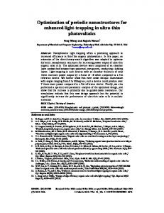
It is because the two internal interface elements cancel each other that there is no reflection at the interface between these two structures. If our aim is to achieve the highest possible transmission in a single direction, we need to match successive iterative reflection coefficients between devices [see Fig. 1(a)]. This is automatically achieved in the case of periodic structures, as the iterative impedances are the same for identical structures. We consider the first two structures depicted in Fig. 1(a), which imply the following scattering composition:
(b
1
iter
⊕ p1iter ⊕ b1iter )⊕ (b1iter ⊕ p1iter ⊕ b1iter ) = b1iter ⊕ p1+1iter ⊕ b1iter
(17)
as in the case of characteristic impedance matching the internal boundaries disappear completely thus the is no internal interface reflectivity. Iterative impedance matching can also be achieved between non-identical structures as depicted in Fig. 1(a) between second and third structures. In this case the internal boundary does not cancel out completely but the reflectivity associated with the matched iterative impedance becomes zero. If for different structures we have both iterative impedances matched than the internal interface has zero reflectivity in both directions and the internal interface elements cancel out completely.
#72976 - $15.00 USD (C) 2006 OSA
Received 12 July 2006; revised 8 August 2006; accepted 8 August 2006 21 August 2006 / Vol. 14, No. 17 / OPTICS EXPRESS 7715
Fig. 1. Matching the iterative reflectivity (a) and the image reflectivity (b).
In general, an entire non-symmetric multilayer structure is matched if, at every interface, between individual elements, the image impedances match each other and that the first and last image impedance match respectively the input and output impedance [see Fig. 1(b)]. One way to achieve this is by reversing the propagation direction of a given structure such that two boundaries with identical image impedance face each other [see Fig. 1(b)]. Using again the decomposition defined in Appendix A, we can define the total scattering matrix of a structure composed with its reverse.
(b
1
image;1
⊕ p1image ⊕ b1image;2 )⊕ (b1image;2 ⊕ pˆ 1image ⊕ b1image;1 )
= b1image;1 ⊕ (p1image ⊕ pˆ 1image )⊕ b1image;1
(18)
Indeed, the internal interface cancels out and the result is a symmetric structure that is already decomposed into interface and bulk elements. Similarly, image impedance matching between different structures can be shown and in each case the internal boundary disappears. 2.6 Transparency and impedance matching Transparency between a sample and its substrate is achieved when the reflectance of the substrate equals the reflectance of the sample on top of the substrate. Here, we clarify the link between the transparency condition and the characteristic impedance matching to vacuum as experimentally demonstrated in Ref. [6]. Indeed, if the sample is symmetric then the transparency condition implies:
sr +
st2 r0 = r0 1− sr r0
(19)
where st and sr are respectively the sample field transmission and reflection coefficients while r0 is the substrate interface field reflectivity coefficient. Equation (19) is not enough by itself to deduce optical impedance matching to vacuum (sr=0) and it implies the following relationship
st = ±
(1− sr r0 )( r0 − sr ) r0
(20)
One-way to simplify this relationship is to check for transparency in the other direction of propagation i.e. substrate followed by sample. If transparency is achieved in both directions of propagation, then we generally have impedance matching to vacuum. Alternatively, demonstrating transparency for substrates with different indices of refraction can be used to conclude on impedance matching to vacuum.
#72976 - $15.00 USD (C) 2006 OSA
Received 12 July 2006; revised 8 August 2006; accepted 8 August 2006 21 August 2006 / Vol. 14, No. 17 / OPTICS EXPRESS 7716
3. Numerical applications 3.1 Symmetric structures: Characteristic and wave impedance matching We have shown in the previous section that depending on the angle of incidence, we need to distinguish between the wave and the characteristic impedance. Indeed, it is only at normal incidence that both impedances are equivalent to each other. For any other angle, it is the wave impedance that needs to be matched in order to achieve low reflectivity at the matched interface. Here, we illustrate this behavior by calculating the effective reflectivity at the interface between two composite multi-layer structures. This is the reflectivity between the structures after being replaced by their homogenous equivalent layer with the effective permittivity εeff and permeability μeff given by Eq. (8). Remark that this replacement implies that even if the materials at an interface are identical one would generally calculate a non-zero reflectivity at this interface between two different structures. This is because the effective optical coefficients take the whole structure into account. Each structure considered is symmetric and consists of a thin gold layer, a glass layer and a final thin gold layer. The difference between the structures is given by the thickness of the glass layer. In the first case considered (see Table 2), we chose the thickness of the glass layer to be such that the two structures are characteristic impedance matched. In this case there is no reflectivity at the interface between the two structures at normal incidence. This no longer holds at 40 degrees incidence angle where the characteristic impedance remains matched but the wave impedances differ. Finally, we changed the thickness of the second structure’s glass layer such that it is wave impedance matched. Again, we observe no reflectivity at the interface despite the mismatch of the characteristic impedance. Table 2. Characteristic and wave impedances matching at a wavelength of 500nm. The structure is defined by three thicknesses corresponding to three successive layers of gold, glass and gold in nm.
Incidence
First structure
Second structure
Effective interface reflectivity
normal
(20, 50, 20) Zc1=0.59+0.45i Zw1=0.59+0.45i
(20, 221, 20) Zc2=0.59+0.45i Zw2=0.59+0.45i
|r|=0 Matched wave and characteristic impedance.
40 degrees
(20, 50, 20) Zc1=0.59+0.45i Zw1=0.74+0.58i
(20, 221, 20) Zc2=0.59+0.45i Zw2=0.56+0.67i
|r|=0.11 Only characteristic impedance matched.
40 degrees
(20, 50, 20) Zc1=0.59+0.45i
(20, 240, 20) Zc2=0.65+0.27i
|r|=0 Only wave impedance matched.
Zw1=0.74+0.58i
Zw2=0.74+0.58i
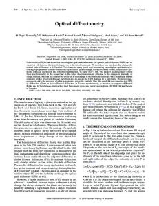
3.2 Periodic structures: Iterative impedance An interesting periodic multi layer structure is the “optical black gold” i.e. impedance matched absorbing gold-dielectric periodic stacks. This structure has reduced reflectivity because of the impedance matching to vacuum but, at the same time, it is absorbing because of its gold layers. Conceptually, it is equivalent to an antireflection-coated gold mirror and can be seen as the physical equivalent to perfectly matched layers [16]. Such matched structures can be used in stealth technology for reflection-less cloaking and invisibility [13,14]. The period of the optical black gold structure we explore is composed of 80nm SiO2, 4nm gold, 24nm SiO2, 4nm gold and 80nm SiO2. For the numerical simulation, we use the experimentally determined refractive index for gold [17, 18] and SiO2 [19]. The different gold and SiO2 thicknesses are optimized to match the characteristic impedance to vacuum. Indeed, #72976 - $15.00 USD (C) 2006 OSA
Received 12 July 2006; revised 8 August 2006; accepted 8 August 2006 21 August 2006 / Vol. 14, No. 17 / OPTICS EXPRESS 7717
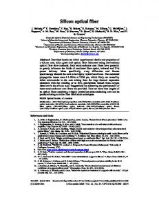
Fig. 2(a) shows that this is achieved from 600nm to 800nm. Further, we verify the reflectionless absorption properties of this periodic structure by calculating the reflectance and transmittance in normal incidence for a finite stack of 100 periods having a total width of 19.2μm [Fig. 2(b)]. A very interesting optical property of the black gold structure is its Brewster angle. Within the impedance framework, the Brewster angle corresponds to the angle for which the iterative impedance (or wave impedance for symmetric structures) is matched to vacuum. For glass, this angle is about 56 degrees for the p polarization and does not exist for s polarization. The presence of the periodic thin gold layers extends the Brewster condition to normal incidence and the s polarization (see Fig. 3).
Fig. 2. (a). Real (red) and imaginary part (blue) of the iterative impedance for the black gold structure. (b) Intensity reflectance (red) and transmittance (blue) as a function of wavelength for 100 periods of the black gold structure.
Fig. 3. Iterative reflectivity as a function of wavelength and angle for the black gold structure. For both polarizations, the black region corresponds to a generalized Brewster angle matching where the black gold structure does not reflect (|riter|2