Jul 20, 2006 - (12) United States Patent ... Attorney, Agent, 0}' FirmiLisa Jorgenson; Paul. Rusyn .... This application claims the bene?t of Italian Patent Appli.
US007582892B2
(12) United States Patent Portico Ambrosio et a]. (54)
US 7,582,892 B2
(10) Patent N0.: (45) Date of Patent:
OPTICALLY CONTROLLED SWITCHING METHODS BASED UPON THE
(52) (58)
POLARIZATION OF ELECTROMAGNETIC RADIATION INCIDENT UPON CARBON
Sep. 1, 2009
US. Cl. ....................................... .. 257/40; 257/421 Field of Classi?cation Search ................. .. 257/40,
257/421E422, 431I448, 1331.001; 977/953E954 See application ?le for complete search history.
NANOTUBES AND ELECTRICAL-SWITCH
_
SYSTEMS USING SUCH SWITCH DEVICES
(75)
(56)
References clted U.S. PATENT DOCUMENTS
Inventors: Michele Portico Ambrosio, Poggiomarino (IT); Maria Grazia
2003/0098488 A1*
Maglione, Torre del Greco (IT); Maria Fortuna Bevilacqua, Gragnano (IT);
5/2003 O’Keeffe et a1. .......... .. 257/401
>1< Cited by examiner
Luigi Occhipinti, Ragusa (IT); Salvatore Coffa, Tremestieri Etneo (IT); Salvatore Castorinas Geneva
(73) Assignee: STMicroelectronics S.R.L., Agrate Brianza (Ml) (IT) ( * ) Notice?
(57)
SubleCI_IO any disclaimeri the term Ofthis
Described herein is an optically controlled electrical-switch device Which includes a?rst current-conduction terminal and a second current-conduction terminal, and a carbon nanotube connected between the ?rst and the second current-conduc
tion terminals, the carbon nanotube being designed to be
_
(22) Flled'
impinged upon by electromagnetic radiation and having an
Jun‘ 7’ 2004
electrical conductivity that canbe varied by varying the polar
.
(65)
.
US 2006/0158760 A1
ization of the electromagnetic radiation incident thereon. In
particular, the carbon nanotube may for example, in given
Jul. 20, 2006
conditions of electrical biasing, present a
'
(IT)
TO2003A0425
’
"""""""""""" "
Int_ CL H01L 3 5/2 4 H01L 51/00 H01L 29/82 H01L 43/00
electromagnetic radiation having a given Wavelength and a polarization substantially orthogonal to the axis of the carbon nanotube Itself
17 Claims, 7 Drawing Sheets
11
7N
9
8
4
l
tially parallel to the axis of the carbon nanotube itself, and a reduced electrical conductivity When it is impinged upon by
(200601) (2006.01) (2006.01) (2006.01)
5
electrical con
ductivity When it is impinged upon by electromagnetic radia tion having a given Wavelength and a polarization substan
FOI‘eigII Application Priority Data
Jun 6 2003
(51)
.
Pnor Pubhcatlon Data
(30)
ABSTRACT
Pawnt 15 extended or adlusted under 35 U-S~C~ 154(b) by 773 days-
(21) Appl' NO‘: 10/863,635 .
P1’imary Examinericuong Q Nguyen Rusyn; Attorney, Graybeal Agent, Jackson 0}’ FirmiLisa LLP Jorgenson; Paul
\
I
I10
1
U S Patent
Sep. 1, 2009
Sheet 1 0f 7
Source (Au)
Drain (Au)
Gate oxide (SiO2)
Gate (Si)
NANOTUBE
SiO2
US 7,582,892 B2
US. Patent
Sep. 1, 2009
Sheet 2 of7
US 7,582,892 B2
-1.0V
-1.1V
-20
- 1.2V
[[nA] Vg = -1.3V
-60
A
_
1,5V
_
d
4 d
-1,5 -1,5
-1 ,0
VINM
Fig.5
406 04
US. Patent
Sep. 1, 2009
US 7,582,892 B2
Sheet 4 0f 7
ENRGYIv] III
10
Fig.8c
Fig.8b POLARIZATION
I]
J.
Am
0
i 1
0v
maintained
inverted
ch
inverted
TRANSITION
A0+ —)A0' ,E1+ —)E1-, 52* *EZ'YEQ" —>E3+'
Fig.9
maintained
E3_ __’E2_I 52+ ->E3+
15
US. Patent
Sep. 1, 2009
Sheet 5 of7
US 7,582,892 B2
| l_. m
_
100-‘
-+m mT
IA'5
O
PHOTON ENERGY [eV]
Fig.1(;
11
A], //10 f
_A
US. Patent
Sep. 1, 2009
Sheet 6 of7
Fig.13
US 7,582,892 B2
US. Patent
Sep. 1, 2009
Sheet 7 of7
US 7,582,892 B2
22
20
1
//
/ I
1/ H
POLARIZATION
LASER
21
—
+
I
CIRCUIT
POCKELS CELL
Fig.14 23 INPUT
24 “
x
OUTPUT
BEAM
BEAM
nni>
unj> y Z
——|
"17’
Fig. 1 5 23 24 INPUT
“
X‘
OUTPUT
BEAM
mi
BEAM
-
_Y_ ,Z_>J Fig.16
mi}
US 7,582,892 B2 1
2
OPTICALLY CONTROLLED SWITCHING METHODS BASED UPON THE POLARIZATION OF ELECTROMAGNETIC RADIATION INCIDENT UPON CARBON NANOTUBES AND ELECTRICAL-SWITCH SYSTEMS USING SUCH SWITCH DEVICES
to make, and subsequently assemble, nanometric components starting from individual atoms or molecules, i.e., ones in
Which the devices involved in handling and retaining the data are molecules arranged and interconnected so as to form a
circuit. Amongst the different molecular structures studied, carbon nanotubes (CNTS) have aroused an enormous interest oWing to their extraordinary physical properties. For a detailed treat ment, see for example the article “Carbon Nanotube-Based
PRIORITY CLAIM
This application claims the bene?t of Italian Patent Appli cation Serial No. TO2003A000425, ?led Jun. 6, 2003, Which
Nonvolatile RandomAccess Memory for Molecular Comput ing”, Science, Volume 289 (5476), Jul. 7, 2000, 94-97.
application is incorporated herein by reference in its entirety.
controlled electrical-sWitch device based upon carbon nano
It is knoWn the property of carbon atoms to organize them selves into different structures, giving rise to materials of different forms. In fact, diamond is made up of carbon atoms organiZed in tetrahedrons, While graphite is made up of car bon atoms organiZed in planar structures. These tWo allotro pic forms, albeit arising from the same type of atoms, exhibit
tubes and to an electrical-sWitch system using the sWitch device. In the last feW years, the considerable success of CMOS
structural properties (hardness, elasticity, friction) and func tional properties (electrical conductivity, color, etc.) that are very different and frequently opposite.
BACKGROUND
Embodiments of the present invention relate to an optically
20
technology has been determined fundamentally by the possi bility of constantly reducing the dimensions of electronic
The structural characteristics, such as hardness and refrac
toriness, of graphite and diamond render it dif?cult to imple
devices. In fact, this technology folloWs the so-called Moore’s laW, according to Which the number of transistors that can be obtained on an integrated circuit and, conse
ment, at nanometric scales, an on-device approach of the 25
quently, the speed of calculation should double in a time range of between 18 and 24 months. However, it is a common conviction that conventional sili con micro-electronics cannot continue inde?nitely to folloW this laW in so far as sooner or later physical limits that prevent current circuits from functioning in a reliable Way at nano
as buckyball, Which has a molecular structure having the 30
metric dimensions Will certainly be reached, While at the
shape of a polyhedral cage, made up of pentagons and hexa gons. The structures of fullerenes, Which develop in the form of long cylinders, rather than in the form of spheres, are called
nanotubes. Their length (several microns) can be thousands of times larger than their diameter (just a feW nanometers).
same time an exponential increase in production costs Will
render any further increase in the levels of integration pro hibitive. By increasing the density of the electronic devices on a chip, in fact, phenomena such as the need to dissipate the heat generated by such dense circuits and the transition from the classic behavior to the quantum behavior of charge cani ers Will considerably sloW doWn progress. In particular, thanks to the use of lithographic techniques, there have currently been reached dimensions of the order of 100 nm. Notwithstanding the rapid progress achieved in the current process of scale integration, current technology is dif?cult to scale further beloW these critical dimensions. In fact, once the critical dimensions have been reached, the
top-doWn type. Instead, an approach of the bottom-up type is made possible by the use of another allotropic form of carbon, namely fullerene. Belonging to the family of the fullerenes is C60, also knoWn
35
Furthermore, using knoWn techniques of molecular synthe sis, there have been observed, in the laboratory, single-Walled cylindrical structures, or single-Walled nanotubes (SWNTs), having a diameter of 1-2 nm, and multiple-Walled structures, or multiple-Walled nanotubes (MWNTs), i.e., ones formed by
40
coaxial cylinders, With diameters of some tens of nanometers. Carbon nanotubes are organic molecules made up of a number of carbon atoms interconnected in a cylindrical struc ture, Which are characterized by a loW Weight and have excep
small electrical currents that carry the information are trans
tional elastic properties that render them extremely hard but also capable of undergoing large deformations Without break ing. Thanks to their exceptional mechanical properties and to their capacity of conducting electrical charges, carbon nano
ferred uncontrollably from one device to the other. In particu lar, When quantum effects start to become important, the transistors tend to lose the electrons that represent the infor
tubes, in so far as they can be con?gured both as conductors and as semiconductors, are suited for forming the compo nents of a neW class of nanometric electronic devices. In
mation, so that it becomes dif?cult to maintain them in the
45
50
original state. It is envisaged that, beloW the dimensions indi
particular, they are believed to play a primary role in the development of molecular electronics on account of the fact that, thanks to their lateral dimensions of the order of the
cated of 100 nm, these dif?culties are likely to become impor tant.
nanometer and their electrical conduction properties, they
The need to solve the above problems has forced research in the direction of the study of neW technologies based upon the use of organic materials that can replace, altogether or in part, silicon in the construction of electronic devices.
behave as quantum conductors of nanometric dimensions 55
Carbon nanotubes have different shapes that can be described by a vector, referred to as chiral vector C, as illus trated in FIG. 1.
Molecular electronics has the potentiality for overcoming the limits of silicon technology in so far as it is possible to
fabricate single molecule devices that organiZe themselves in parallel by means of self-assembly techniques, Which are also
In particular, in geometrical terms, a carbon nanotube can 60
economically advantageous. The need has thus arisen to explore the possibility of pass
ing from current assembly technologies of the top-doWn type, Whereby it is possible to reach the desired dimensions With successive removals of a macroscopic amount of a material,
to technologies of the bottom-up type, Whereby it is possible
(“quantum nanoWires”).
65
be obtained from a sheet of graphite, by “cutting” it along lines (dashed lines in FIG. 1) perpendicular to the chiral vector and by “rolling” it in the direction of the chiral vector itself. In this Way, a cylinder of diameter d:|C|/J'|§ is formed. The chiral vector consequently de?nes the type of Winding to Which the individual sheet of graphite is subjected in order to give rise to a particular carbon nanotube. When the sheet of graphite is Wound to form the cylindrical part of the carbon
US 7,582,892 B2 3
4
nanotube, the ends of the chiral vector are joined. The chiral vector hence represents a circumference of the circular sec
charge, or else chemical-vapor deposition (CVD). For a more detailed treatment as regards the latter technique see for
tion of the nanotube.
example H. M. Cheng et al., Appl. Phys. Lett. 72, 3282
(l 998).
The chiral vector C can be set in relation to tWo unit vectors
al and a2 that de?ne the lattice of the planes in the graphite, by
In particular, the latter technique is compatible With the
means of tWo indices n and m, according to the following
methods used in the micro-electronics industry and enables
equation:
nanotubes to be groWn on substrate. Using the various tech niques, it has been found that the carbon nanotube that can be
produced in the largest quantity is the carbon nanotube (l0, Linked to the indices n and m are an angle 4), referred to as
10).
chiral angle, and
As has been said, carbon nanotubes constitute a Way for responding to the need to reduce the dimensions of devices in integrated circuits. In fact, by means of the versatile mol
ecules, the path has been opened to the construction of
the diameter d of the carbon nanotube according to the fol
loWing equations:
20
The values of the indices n and m de?ne the chirality of the carbon nanotube, Which is the state of the carbon nanotube
molecular transistors. In the last feW years, different con?gurations of ?eld-effect transistors have been proposed that use carbon nanotubes With semiconductor properties as channels for the transport of electrical charges. Some research groups (R. Martel et al. of the IBM Research Division, ChongWu Zhou et al. of the University of Southern California, etc.) have obtained a so
called “back-gate” con?guration, illustrated, in schematic
itself, Which differs according to the Way in Which the hexa
cross section, in FIG. 2, in Which the substrate functions as
gons of the graphite arrange themselves in forming the cylin
gate of the device. The con?guration renders, hoWever,
drical structure. The chirality of a carbon nanotube is thus
25
given by the pair of integer indices (n, m) and determines the structural characteristics and, consequently, the electrical conduction properties of a carbon nanotube. In particular, in relation to the structure, nanotubes that have the indices n and m equal, i.e., nanotubes (n, n), are referred to as armchair nanotubes on account of the arrangement of the hexagons of
30
impossible the integration of a high number of devices on one and the same chip. In fact, in this case it Would be necessary to apply the same gate voltage to all the transistors on the chip. For a more detailed treatment of the subject, see R. Martel, T.
Schmidt, H. R. Shea, T. Hertel, and Ph. Avouris, App. Phys. Lett. 73, 2447 (1998) and C. Zhou, J. Kong, E.YenilmeZ, H.
Dai, Science, 290, 1552 (2000).
graphite With respect to the axis of the carbon nanotube itself;
Subsequently, in 1998 researchers of the Dekker group of
nanotubes in Which one of the tWo indices is Zero (n, 0) are
Delft University of Technology developed carbon-nanotube
referred to as ZigZag nanotubes; nanotubes for Which the
?eld-effect transistors (CNT-FETs) using an innovative con
relation m:0 or else n:m is valid are referred to as achiral 35
nanotubes; While nanotubes With different indices are in gen
?guration referred to as “local gate” con?guration, illustrated in FIG. 3, Which enables integration of a large number of
eral referred to as chiral nanotubes.
devices on a single chip. For a more detailed treatment of the
The chirality conditions the conductance of the carbon nanotube, its density, its lattice structure, and other proper ties. The chiral indices can, in principle, be obtained experi
Science, 294, 1317(2001).
subject see A. Bachtold, P. Hadley, T. Nakanishi, C. Dekker, 40
mentally, by measuring the chiral angle 4) and the diameter d
Broadly speaking, in the CNT-FETs the channel is consti tuted by a carbon nanotube functioning at room temperature,
of the carbon nanotube With a transmission electron micro
and the local gate is insulated from the carbon nanotube by
scope (TEM) or With a scanning tunneling microscope
means of an oxide layer ofjust a feW nanometers in thickness.
In particular, tWo gold electrodes Were deposited, Which func
(STM). Furthermore, according to their chirality the nanotubes can
45 tion as source and drain, on a silicon oxide substrate groWn on
be metallic nanotubes or semiconductor nanotubes. In fact,
silicon, Which functions as gate, and these tWo electrodes Were connected With a single-Walled nanotube (SWNT), Which functions as channel. The current-voltage characteris
nanotubes Whose chirality indices satisfy the folloWing rela tion:
tic of this three-terminal device Was measured and it Was n-m:3-II:0, 1,2,. ..
50
are metallic and, hence, conductors; all the others have a nonZero bandgap and, consequently, behave as semiconduc tors. Armchair nanotubes are metallic.
The fundamental bandgap of a semiconductor carbon nanotube depends upon the diameter d of the carbon nano tube, on the basis of the folloWing relation: E
55
IZyOaCC/d
Where yO is the binding energy of the carbon atoms, and ass is the distance betWeen tWo neighboring carbon atoms.
60
Consequently, by appropriately modifying the chirality of
Carbon nanotubes can be produced in macroscopic amounts using different techniques: laser ablation, arc dis
by an aluminium Wire With an insulating layer of A1203, Which separates it from the carbon nanotube. The semicon ductor carbon nanotube is set in electrical contact With the
tWo gold electrodes. The thickness of the A1203 layer (a feW nanometers) is much smaller than the separation betWeen the electrodes (~l00 nm). This determines an excellent capaci tive coupling betWeen the gate and the carbon nanotube, the consequences of Which result in a gain in voltage greater than 10 and in a Wide range of the output signal. It is possible to design various aluminium local gates in such a Way that each
the carbon nanotube and, hence, its diameter, it is possible to modulate its bandgap. The tWo different geometrical struc tures of the molecule (i.e., the initial one and the modi?ed one) can thus represent tWo stable states.
veri?ed that it respected the characteristic of a ?eld-effect transistor. In particular, FIG. 3 illustrates a schematic cross section of the local-gate CNT-FET. The gate in the device is constituted
Will address a different CNT-FET. 65
Formation of circuits comprising CNT-FETs is articulated in three fundamental steps. In the ?rst step, the gate is
obtained by delineating the aluminium pattern via electron
US 7,582,892 B2 6 PPyPV (poly{(2,6-pyridinylene-vinylene)-co-[(2,5-dio
5 beam lithography (e-beam lithography) on an oxidized sili
ctyloxy -p -phenylene)vinylene] }).
con Wafer. The layer of insulating material is represented by an oxide groWn by exposing the specimen to air. The thick ness of the layer cannot be determined With great precision
The tWo polymers indicated above are structurally similar and, in solution, are characterized by the same absorption spectrum With a peak in the proximity of 420 nm. The most signi?cant difference is linked to the fact that the PPyPV is a
but is in the order of a feW nanometers. The second step
consists, instead, in dispersing single-Walled nanotubes (SWNTs), previously produced by laser ablation, on the
base and, for this reason, is protonated by the HCl present in the solution in Which the polymer is dissolved. The interac tion With the carbon nanotubes favors the protonation pro cess. The device obtained consists simply of tWo metal elec trodes, betWeen Which are arranged the polymer/CNT blends
Wafer starting from a suspension of dichloroethane. The nanotubes of appropriate diameter (~1 nm) are selected and positioned on the top part of the aluminium gate. An alterna
tive technique envisages the groWth in situ of the nanotubes
using the chemical-vapor-deposition (CVD) technique assisted by orienting electrical ?elds (for a detailed treatment
(polymer-Wrapped SWNTs), deposited by spin coating.
of the subject seeY. Zhang, A. Chang, J. Cao, Q. Wang, W. Kim, Y. Li, N. Morris, E. YenilmeZ; J. Kong, H. Dai, App. Phys. Le”. 79, 3155 (2001)). Finally, the last step consists in
The above polymers and the carbon nanotubes are in elec trical contact: in this Way, it is possible to use radiation of
appropriate Wavelength for the purpose of modulating the
the formation of electrodes and interconnections via electron
electrical conductivity of the ropes of carbon nanotubes. The
beam lithography, evaporating gold directly on the carbon nanotube Without intermediate adhesion layers.
researchers carried out a series of measurements at different
The CNT-FET illustrated in FIG. 3 is a p-type device
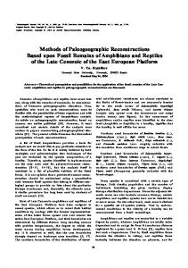
functioning by enrichment since it is possible to obtain a marked modulation of the current through the FET by apply ing a small negative voltage to the gate. Furthermore, by acting on the gate voltage it is possible to vary the carrier concentration of the carbon nanotube, up to reversing its polarity from the p-type regime to the n-type regime. FIG. 4 illustrates the current/source-drain voltage charac
20
current responses obtained are illustrated in FIGS. 6a, 6b, and
60, respectively. 25
teristics (l/Vsd) of the transistor measured at room tempera
ture for different values of the gate voltage (Vg). As may be noted, the trend of the curves is typical of traditional FETs With ?nite values of the current, When the gate voltage is
Wavelengths for devices containing just ropes of CNTs, PmPV-Wrapped/CNTs and PPyPV-Wrapped/CNTs, and the
30
In particular, as emerges clearly from FIG. 6a, in the devices containing only CNTs no type of optically modulated response is detected. FIGS. 6b and 60 show, instead, the responses of the PmPV-Wrapped/CNTs device With negative and positive electrical biasing, respectively. The variation of the output response is the same Whatever the electrical biasing and is approximately 15-20% of the total current. In particu lar, there appears a photo-ampli?cation of the current for
negative and smaller than the threshold voltage Vt Wt~—l .0
positive biasing, i.e., the intensity of the total current in the
V).
device (dark current plus photogenerated current) increases,
The same research group mentioned above proposed,
moreover, the possibility of making some elementary logic circuits based upon CNT-FETs. The applications (OR gates, AND gates, NOT gates, SRAMs) Were obtained using the resistor-transistor logic scheme and forming the CNT-FETs
35
on the same chip.
FIG. 5 gives the input-output transfer characteristics of a logic inverter With carbon-nanotube FETs and a pull-up resis tor on the outside the chip With the value of 100 M9. The researchers identi?ed the voltage of —1.5 V as an appropriate
value for logic applications (logic 0:0 V, logic 1:—1.5 V). When the input of the logic inverter assumes the logic value “1” (Vin:—1.5 V), the negative gate voltage induces a move
40
45
(light ON-light OFF) there corresponds a sWitching of the The fundamental limits of the above devices are linked 50
55
California. For a detailed treatment of the subject see D. W. 60
3124 (2002). The above Work investigated the interactions betWeen single-Walled carbon nanotubes (SWNTs) and tWo types of
PmPV (poly{(m-phenylene-vinylene)-co-[(2,5-diocty loxy-p-phenylene)vinylene] }), and
controlled electrical sWitches. In fact, as is evident from
electrical signal at output.
controlled molecular device based upon carbon nanotubes
polymers:
observed for negative biasing, While for positive biasing the
FIGS. 6b and 60, to a sWitching of the optical signal at input
has been proposed by a research group of the University of
Steuerman, A. Star, R. NariZZano, H. Choi, R. S. Ries, C. Nicolini, J. F. Stoddart, J. R. Heath, .1. Phys. Chem. B 106,
FIG. 7 illustrates, instead, the current response of a device With PPyPV-Wrapped/CNTs. As may be noted, no effect is
effect of photo-ampli?cation is substantially greater as com pared to the previous case illustrated in FIGS. 6a, 6b, and 60. Using structures of this type, it is possible to make optically
ment of electron holes in the carbon nanotube giving it a
resistance that is considerably smaller than the pull-up resis tance, and this pushes the output to the logic value “0” (VOMIO V). When the input assumes instead the logic value “0” (VMIO V), the carbon nanotube is not conductive and the output assumes the logic value “1” (Vout:—1.5 V). Recently, some studies have demonstrated the possibility of making molecular devices With non-electrical control using carbon nanotubes. lnparticular, an example of optically
in absolute value, When the light at input is ON; on the other hand, for negative biasing there is a photorecti?cation; con sequently, in conditions of illumination the total current diminishes.
65
basically to the complexity of their implementation in inte grated technology on account of the technique used for depositing the polymer/CNT blend. The spin-coating tech nique, in fact, renders it extremely dif?cult to de?ne on the chip delimited areas on Which to deposit the solution. The delineation of these areas Would require a further process of
controlled removal of the “spin-coated” solution, to be appro priately de?ned on the basis of the properties of the starting solution. Furthermore, spin coating does not enable a good control of the uniformity of thickness of the deposited ?lm to be obtained. Another important embodiment is linked to the loW tem peratures at Which the devices have been made and tested (TOPI4 K). From the literature, in fact, their behavior at room temperature is not knoWn. The purpose of embodiments of the present invention is to provide an optically controlled electrical-switch device that
US 7,582,892 B2 7
8
Will enable the drawbacks of the known devices described
An innovative idea underlying embodiments of the present invention draWs origins from different theoretical studies regarding the electronic and structural properties of carbon nanotubes that have highlighted hoW these molecular struc tures have the property of optical dichroism.
above to be overcome at least in part.
SUMMARY
According to an embodiment of the invention an optically
controlled electrical-switch device is provided.
DETAILED DESCRIPTION
According to an embodiment of the invention, there is provided an electrical-sWitch system. According to an embodiment of the invention, there is further provided an optical-control method of an electrical sWitch device. According to an embodiment of the invention, there is provided a fabrication process of an optically controlled elec trical-sWitch device.
The folloWing discussion is presented to enable a person skilled in the art to make and use the invention. Various
modi?cations to the embodiments Will be readily apparent to those skilled in the art, and the generic principles herein may be applied to other embodiments and applications Without departing from the spirit and scope of the present invention. Thus, the present invention is not intended to be limited to the embodiments shoWn, but is to be accorded the Widest scope consistent With the principles and features disclosed herein. In general terms, optical dichroism is the property of a
BRIEF DESCRIPTION OF THE DRAWINGS
For a better understanding of the present invention there is noW described an embodiment, provided purely by Way of non-limiting example and With reference to the annexed
means to absorb in a different Way the tWo components of 20
draWings, in Which: FIG. 1 shoWs the geometrical characterization of a carbon
nanotube; FIG. 2 shoWs a schematic cross section of a carbon-nano
25
tube PET in the back-gate con?guration; FIG. 3 shoWs a schematic cross section of a local-gate
CNT-FET; FIG. 4 shoWs voltage/current characteristics measured at room temperature for different gate-voltage values of a CNT
30
FIG. 5 shoWs the transfer characteristic of a logic inverter
With CNT-FETs; FIGS. 6a, 6b, and 60 show the current responses, respec 35
of an optically controlled device obtained With PmPV
Wrapped/CNTs With negative electrical biasing, and of an optically controlled device obtained With PmPV-Wrapped/ CNTs With positive electrical biasing, in the presence and in the absence of incident light;
In particular, in an axisymmetrical means the tWo compo nents of polariZation of light referred to are the one parallel to and the one orthogonal to the optical axis. In practice, a dichroic means behaves like a polariZing sheet: one direction of polariZation is totally or partially trans mitted, the one orthogonal thereto is absorbed. The purpose of embodiments of the present invention is
thus to exploit the property of optical dichroism of nanotubes in order to provide an electrical-sWitch device capable of sWitching betWeen the tWo operating states, open and closed,
by simply varying the polariZation of the light incident upon
FET;
tively, of an optically controlled device obtained using CNTs,
polariZation of light that propagates in an anisotropic means.
the device itself. The property of optical dichroism has been observed both in chiral nanotubes and in achiral nanotubes. Furthermore, different experimental studies have demonstrated that ?lms of aligned nanotubes are birefringent on account of the dif ference in the dielectric functions for light polariZed in a direction orthogonal to and a direction parallel to the axis of the nanotubes itself. In particular, a Work has recently been
40
FIG. 7 shoWs the current response of an optically con
published (I. BoZovic, N. BoZovic, M. Damnjanovic, Phys. Rev. B 62, 6971 (2000)) regarding the effect of optical dichro
trolled device obtained With PPyPV-Wrapped/CNTs in the
ism in an individual carbon nanotube. The effect is linked to
presence and in the absence of incident light and as the Wave
the speci?c rules of selection of the linear group for interband
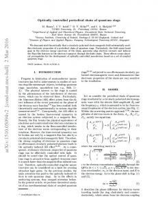
length of the incident light varies; FIGS. 8a, 8b, and 80 show, respectively, the model of a single-Walled carbon nanotube, namely, a ZigZag (4,0) nano
transitions. In BoZovic’s Work a single-Walled carbon nano 45
tube is considered, namely a ZigZag (4, 0) nanotube With
50
translational lattice pitch along the axis of the carbon nano tube a:4.26 A. The spatial-symmetry group of the carbon nanotube is the linear group L84/mcm; this code is connected to the set of different symmetry properties of the carbon nanotube having a cylindrical geometry and refers to the
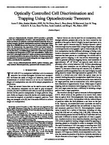
tube, the corresponding band structure, and the correspond ing electron density of states; FIG. 9 shoWs a table of the rules of selection for the absorp tion of the incident light upon a carbon nanotube; FIG. 10 shoWs the absorption spectrum of a carbon nano tube for light polariZed in a direction parallel to and perpen dicular to the axis of a carbon nanotube;
symmetries of rotation about the vertical axis of the tube (8 4) and to the symmetries of re?ection corresponding to the tWo planes (UV and oh) that cross section the carbon nanotube, as indicated in FIG. 8a.
FIG. 11 shoWs a possible implementation on silicon of an
optically controlled electrical-sWitch device according to an
55
embodiment of the present invention; FIG. 12 shoWs the circuit diagram of a logic inverter With active load using an optically controlled electrical-switch device according to an embodiment of the invention; FIG. 13 shoWs a possible implementation on silicon of the
60
logic inverter of FIG. 12;
screW axis: rotation of (X:2J'|§/ 8 about Z folloWed by a trans
lation of (a/2) along Z; plane of vertical re?ection xZ: ov;
FIG. 14 shoWs a different possible use of an optically controlled electrical-sWitch device according to an embodi
ment of the invention; and FIGS. 15 and 16 shoW the diagrams of tWo electro-optical sWitches, respectively, according to an embodiment of the present invention and according to the knoWn art.
FIGS. 8a, 8b, and 8c illustrate, respectively, the model of the carbon nanotube, the corresponding band structure, and the corresponding electron density of states. In particular, the symmetry groups of the system illustrated in FIG. 8a are represented by:
plane of horizontal re?ection xy: oh. It is recalled that a symmetry group is constituted by the set 65
of all the operations of symmetry of the cylindrical system With Which a carbon nanotube can be geometrically schema tiZed. The term “group” is used in a mathematical sense and
US 7,582,892 B2 10 If the light is circularly polarized in the plane orthogonal to
indicates that all the operations of symmetry of the system are reunited so as to form a non-empty set that satis?es Well
the axis of the carbon nanotube (i.e., the direction of propa
determined mathematical conditions, Which represent the formal properties of a group (closure property, associative
transitions betWeen bands such that Am::1 can occur. The
gation is parallel to the axis of the carbon nanotube), only sign : depends upon the phase difference (900 or else —90°) of the tWo components of the polarization vector. The table of FIG. 9 presents, among other things, the tran sitions alloWed corresponding to the different states of polar ization of the incident light. The ?rst column of table of FIG. 9 lists the parameters of polarization. The second column of
property, existence of the neutral element, existence of a
single inverse element). The electron density of states (DOS) of carbon nanotubes has a continuous energy-band structure, separated by energy gaps not accessible to electrons, the so-called bandgaps. The structure of these bands, their energy Width, and the values of the gaps betWeen the bands depend upon the characteristics of the carbon nanotube (single-Wall or multi-Wall, zigzag or
the table list the parameters associated With linearly polarized light parallel to the axis of the carbon nanotube. The third
armchair), and upon the indices n and m. The band structure of the carbon nanotube is obtained
column of the table lists the parameters associated With cir
using the “tight-binding” model (Neil W. Ashcroft, N. David Mermin, Solid State Physics, Philadelphia: Saunders College (1976)), through Which the energy spectrum is obtained:
nanotube. For semiconductor carbon nanotubes like the one consid
cularized polarized light orthogonal to the axis of the carbon ered, if the energy of the photon is greater than the gap
20
betWeen bands, a signi?cant photoconductivity due to a tran sition of electrons from the valence band to the conduction band is observed.
25
position of the ?rst intense peak of interband transition, is markedly dependent upon the polarization of the incident electromagnetic radiation, as highlighted in FIG. 10, Which illustrates the absorption spectrum for electromagnetic radia
The optical absorption spectrum and, in particular, the The above expression shoWs the dependence of the energy upon the variables k and m and consequently indicates the
possibility of reconstructing the entire band structure of the nanotube according to the value assumed by the variables k
tion polarized in a direction parallel to and a direction per pendicular to the axis of a carbon nanotube of the type con sidered.
and m.
In the above expression: In is the angular momentum Which, in the case of the optical transitions for the system considered, can assume the
30
values 0, :1, :2, :3, 4; k is the quantum number indicating the quasimomentum along the Z axis, connected to rules of crystalline symmetry of the structure considered; a is the lattice pitch of the carbon nanotube; 0t is the angle of rotation, corresponding to 275/8; and [3 is the energy associated to the term of overlapping of orbitals belonging to adjacent atoms; this term provides an indication of the overlap energy contribution linked to the distribution of the atoms arranged according to the crystallo graphic structure considered. As highlighted in FIG. 8b, the valence and conduction
tube itself. In particular, a light is sent onto the carbon nanotube of a 35
40 one.
FIG. 11 illustrates, by Way of non-limiting example, a
45
possible structure of an optically controlled electrical-switch device using a carbon nanotube according to an embodiment of the invention. As may be noted, the sWitch device, designated as a Whole by 1, can be obtained in a very simple Way by depositing on a substrate 2 of monocrystalline silicon a thin layer of silicon oxide (SiO2) 3 and then forming on the silicon-oxide layer 3
50
a planar Waveguide 4, Which can, for example, be obtained by simply depositing a thin strip of silicon nitride (Si3N4) 5 on the silicon-oxide layer 3.
and degenerate bands, designated by E. The degenerate energy bands are characterized by the fact that to each energy E(k) there corresponds more than one state.
Since the wavelength 7» of visible light is large if compared to the lattice pitch a of the carbon nanotube, the conservation
of linear momentum implies AkzO, Where Ak represents the difference betWeen the values of the crystalline momentum k of the electron, before and after an interband transition; the crystalline momentum is introduced into the theory of solids, and to a ?rst approximation can be identi?ed With the linear momentum of the electron. This means that the optical transitions alloWed are basi
cally vertical; by the term “optical transitions” is meant radia tive electron transitions, i.e., ones With absorption (in excita tions) or emission (in de-excitations) of radiation. As regards the angular momentum of the electron involved in the transition, the rules of selection depend upon the ori
The structure thus obtained is then coated With a second
silicon-oxide layer 6, and a pair of WindoWs 7, 8 is then opened in the second silicon-oxide layer 6 so as to expose tWo 55
bands so that Am:0 are alloWed.
portions of the strip of silicon nitride 5 that function as input and output ends of the Waveguide 4. In this con?guration, the silicon oxide 3, 6 functions as cladding of the planar Waveguide 4, While the silicon nitride 5 functions as core of
60
the planar Waveguide 4. The refraction indices of SiO2 and Si3N4 are, respectively, 1.46 and 2.05, and these values of the refraction indices do not determine any restriction on the
entation of the electrical ?eld associated to the electromag netic radiation incident upon the carbon nanotube. If the
incident light is linearly polarized parallel to the axis of the carbon nanotube, then only the transitions betWeen pairs of
Wavelength such that the corresponding energy of the photon may induce certain given electron transitions if the radiation is polarized in an appropriate direction With respect to the axis of the carbon nanotube, and may not induce transitions if it is, instead, polarized in a direction orthogonal to the previous
bands are symmetrical With respect to the zero value of energy
and are divided into non-degenerate bands, designated by A,
Consequently, by illuminating a semiconductor carbon nanotube With appropriate radiation, it is possible to induce interband transitions of electrons, via photon absorption, With consequent variation of the conductivity of the carbon nano
65
angle of acceptance of the Waveguide 4, Which is de?ned as the maximum angle Whereby the external radiation can impinge upon the Waveguide 4 so as to be conveyed Within it. On top of the second silicon-oxide layer 6, on opposite sides of one of the tWo WindoWs opened in the second silicon oxide layer 6 itself, in the example illustrated in FIG. 11 the
US 7,582,892 B2 11
12
WindoW 7, tWo electrodes 9, 10 are obtained, for example
The tWo states of polariZation of the light incident upon the
made of gold, Which function as contacts of the switch device
carbon nanotube, consequently, correspond to different val ues of absorption of light by the carbon nanotube itself and,
1. In a position facing the end of the Waveguide 4 exposed through the WindoW 7, there is then set a carbon nanotube 11,
hence, to tWo different states of conductivity of the carbon
nanotube (high conductivityiHIGH state, loW conductiv ityiLOW state). Once the electrical biasing of the sWitch device, the intensity of the incident light, and its Wavelength (and hence the energy of the photons) are ?xed, it is possible to control the sWitch device simply by rotating the polariZa tion of the incident light. FIG. 12 illustrates, by Way of non-limiting example, one of
Which is set in electrical contact With the tWo electrodes 9, 10.
By then sending, on the other end of the Waveguide 4, exposed through the WindoW 8, Which is opened in the second oxide layer 6, electromagnetic radiation having a frequency and polarization, With respect to the axis of the carbon nano tube 11, such as to induce therein interband electron transi
tions, the electromagnetic radiation, after having traversed the stretch of Waveguide 4 set beloW the second silicon-oxide layer 6, comes out of the end of the Waveguide 4 facing the
the possible uses of the optically controlled electrical-sWitch
carbon nanotube 11 through the WindoW 7, impinging upon
ticular, FIG. 12 illustrates the circuit diagram of a logic inverter With active load, designated as a Whole by 12, in Which the active load, designated by 13, is constituted by an electrically controlled pull-up transistor With its channel con stituted by a carbon nanotube, While the pull-doWn transistor is constituted by the sWitch device 1 according to the embodi ment of the invention previously discussed With reference to
device according to an embodiment of the invention. In par
the carbon nanotube 11.
The consequent photon absorption by the carbon nanotube 11 brings about an interband electron transition and a marked
increase in the electrical conductivity of the carbon nanotube 11 itself; the electrical behavior of the sWitch device 1 may consequently be likened to that of a closed sWitch.
20
FIG. 11. The embodiment of FIG. 12 may include an electrical
By sending, instead, on the ?rst end of the Waveguide 4
exposed through the WindoW 8, electromagnetic radiation having polariZation such as not to bring about any photon absorption by the carbon nanotube 11, no interband electron transition is brought about, and hence no increase in its elec trical conductivity; the electrical behavior of the sWitch
biasing device 14 for biasing the carbon nanotube 11, through Which it is possible to vary the electrical biasing of the carbon 25
incident thereon. The sWitching times of the logic inverter are linked to the electron transitions induced by the incident radiation. The
device 1 may consequently be likened to that of an open sWitch.
The solution proposed provides a number of degrees of
absorption of radiation brings about transition of electrons to the conduction band, With creation of electron/hole pairs and consequent increase in the conductivity of the carbon nano
freedom on Which to act for the purposes of controlling the sWitch device. In fact, it is possible to act on the operating
state of the sWitch device either by appropriately choosing the Wavelength of the incident radiation, or else by regulating the
electrical biasing of the sWitch device, i.e., the voltage applied to the carbon nanotube set betWeen the electrodes.
nanotube 11 itself and, consequently, absorption of the light
tube (HIGH state), While, in the absence of absorption of 35
In fact, for given Wavelengths the radiation is absorbed only if it has a polariZation parallel to the axis of the carbon
radiation, there are no interband transitions (LOW state). Consequently, the sWitching times are correlated to the times of the electron transitions, Which are in the order of 10 ns. FIG. 13 illustrates a possible implementation on silicon of the logic inverter of FIG. 12, in Which parts that are the same
nanotube; for other Wavelengths, there Will be absorption
as the ones of FIG. 11 are indicated With the same reference
only for radiation polariZed in a direction orthogonal to the axis; and, ?nally, for yet other Wavelengths there Will be no absorption in either of the tWo directions of polarization. Furthermore, the absorption spectrum of the carbon nano tube, i.e., the position of the absorption peaks as a function of the Wavelength changes if the electrical biasing of the carbon nanotube is modi?ed, so that the electrical biasing may, for example, be ?xed in such a Way that the energy of the incident
numbers. In particular, as illustrated in FIG. 13, the pull-doWn tran sistor has a structure altogether identical to that of the sWitch device 1 illustrated in FIG. 11, in Which the tWo electrodes 9,
40
10 noW function as drain and source terminals of the pull 45
transistor 13, Which functions as active load and has its chan
nel formed by a carbon nanotube, is obtained by depositing, on the second silicon-oxide layer 6, a layer of polycrystalline silicon 15, Which has the function of gate terminal of the
photons of a given Wavelength (excitation energy) Will, for example, be smaller than the bandgap energy for the perpen dicular polariZation of the incident radiation and greater than
the corresponding bandgap energy for the parallel polariZa
50
55
incident photons, since it is smaller than the bandgap energy,
60
source terminals 17, 18, Which are also made of gold, are obtained on the silicon-oxide layer 16 and betWeen them a semiconductor carbon nanotube 19, Which functions as chan
nel, is then deposited, or groWn, according to the used tech
nique. In particular, the drain terminal 9 of the pull-doWn transistor 1 and the source terminal 18 of the pull-up transistor 13 are made integral With respect to one another, so as to
de?ne the output terminal of the inverter, While the gate terminal 15 of the pull-up transistor 13 is connected to the drain terminal 17 of the pull-up transistor 13 itself in a Way knoWn and not illustrated.
is not able to activate any type of transition; the effect of
absorption, in this case, is extremely reduced. The measured
photocurrent consequently varies drastically With the tWo different polariZations of the incident light. In this case, a tunable light source is not necessary: the
pull-up transistor 13, on Which a further very thin layer 16 of
silicon oxide is subsequently formed. Then, the drain and
tion of the incident radiation. In this case, if radiation that is polariZed in a direction parallel to the axis of the carbon nanotube impinges on the carbon nanotube, the energy associated to the photons is greater than the bandgap energy and the radiation is absorbed in so far as it is able to activate the interband transitions, While if the incident radiation is polariZed in a direction perpendicu lar to the axis of the carbon nanotube, then the energy of the
Wavelength and the intensity of the light can be ?xed While the electrical biasing of the carbon nanotube is modi?ed.
doWn transistor 1 itself. The electrically controlled pull-up
FIG. 14 shoWs, by Way of non-limiting example, a different 65
possible use of the sWitch device 1 according to an embodi ment of the invention. In particular, FIG. 14 illustrates a block diagram of a system for the activation of an electric circuit by
means of an optical signal With control of polarization.
US 7,582,892 B2 13
14
In detail, as illustrated in FIG. 14, an optical signal coming, for example, from a laser light source 20, is supplied at input
The described embodiments of sWitch device 1 and sys tems including the sWitch device may be utilized in a variety of different types of electronic systems, such as computer
to an electrical-switch device 1 according to embodiments of the invention, Which issues a command for activation of a
systems and memory systems.
circuit 21 set doWnstream, according to the polarization of the
What is claimed is: 1. An optical-control method of an electrical-sWitch device comprising a ?rst current-conduction terminal and a second
optical signal supplied at input thereto. In particular, the polarization of the optical signal supplied by the laser light source 20 can be controlled by means of a control circuit 22 of the type illustrated in FIG. 15. This is
current-conduction terminal, and a carbon nanotube con nected betWeen said ?rst and second current-conduction ter
made up of a light polarizer 23, Which linearly polarizes the light coming from the laser light source 20, and by a Pockels cell 24, Which is set doWnstream of the light polarizer 23 and is capable of rotating the direction of polarization of the light coming out of the light polarizer 23, via application of an appropriate external voltage V, by causing it to vary betWeen the tWo states parallel and perpendicular to the axis of the carbon nanotube of the electrical sWitch 1 according to an embodiment of the invention. As is knoWn, a Pockels cell is a cell that exploits the so-called Pockels effect and is basically formed by an appro
minals, said method comprising the steps of: impinging upon said carbon nanotube With electromag netic radiation; and varying the polarization of the electromagnetic radiation incident upon said carbon nanotube in order to vary the
electrical conductivity of the carbon nanotube itself. 2. The method according to claim 1, Wherein said step of
varying the polarization of the electromagnetic radiation inci 20
priate crystal, to Which, by applying a potential difference, a
the carbon nanotube to Which there corresponds, in a
variation of the index of refraction along an axis is induced.
given condition of electrical biasing of the carbon nano tube, a high electrical conductivity of said carbon nano
This, in turn, induces a birefringence effect proportional to
the applied voltage, thus creating a system capable of varying the plane of polarization of the light.
tube, and generating electromagnetic radiation having a given Wave length and a second polarization substantially orthogo nal to said ?rst polarization, to Which there corresponds,
From an examination of the characteristics of the optically controlled electrical-switch device obtained according to
embodiments of the present invention, the advantages that it
in said condition of electrical biasing, a reduced electri
makes possible are evident.
In particular, by exploiting the property of optical dichro
30
ism of carbon nanotubes, the present invention makes avail able an electro-optical sWitch device of nanometric dimen sions Which is driven by acting, rather than upon the presence/ absence of light, as occurs in electro-optical sWitch devices according to the knoWn art, but upon the polarization of the
incident upon said carbon nanotube for varying its con
dition of absorption of said incident electromagnetic radiation. 4. The method according to claim 1, Wherein the method
Furthermore, embodiments of the present invention enable
further comprises the step of:
an electro-optical sWitch to be obtained having a structure
simpler than that of electro-optical sWitch devices according 40
using the diagram illustrated in FIG. 16, i.e., arranging in cascaded fashion: a ?rst light polarizer for linearly polarizing the input light in a given direction; a Pockels cell, for rotating the direction of polarization of the light coming out of the light polarizer via the application of an appropriate external
45
voltage; and a second light polarizer for linearly polarizing the light coming out of the Pockels cell in a direction perpen
dicular to that of the ?rst polarizer. By acting appropriately upon the voltage applied to the Pockels cell, it is possible to cause the electromagnetic radiation to come out or otherWise 50
from the second polarizer. By detecting the presence or absence of the electromagnetic radiation at output from the
second polarizer, for example via an appropriate optical detector circuit, it is possible to control activation or deacti vation of a circuit set doWnstream of the electro-optical sWitch device.
55
Using, instead, the sWitch device according to embodi ments of the invention, it is possible to do Without the second
polarizer, and this possibility becomes particularly important for construction of nanometric electro-optical devices, in so
60
varying an electrical biasing of said carbon nanotube for varying its condition of absorption of the incident elec
tromagnetic radiation. 5. The optical-control method of claim 2, Wherein the ?rst polarization With respect to the axis of the carbon nanotube corresponds to a polarization that is substantially parallel to the axis of the carbon nanotube; and Wherein the second polarization With respect to the axis of the carbon nanotube corresponds to a polarization that is substantially orthogonal to the axis of the carbon nano tube. 6. The optical-control method of claim 2, Wherein the ?rst polarization With respect to the axis of the carbon nanotube corresponds to a polarization that is substantially orthogonal to the axis of the carbon nano
tube; and Wherein the second polarization With respect to the axis of the carbon nanotube corresponds to a polarization that is substantially parallel to the axis of the carbon nanotube. 7. The optical-control method of claim 1 Wherein the elec tromagnetic radiation has a Wavelength Within the spectrum
of visible light.
far as the absence of a second polarizer reduces the overall
dimensions considerably.
8. The optical-control method of claim 1 Wherein the elec
tromagnetic radiation is circularly polarized in a plane
Finally, it is clear that modi?cations and variations may be made to the optically controlled electrical-switch device
described and illustrated herein, Without thereby departing
cal conductivity of said carbon nanotube. 3. The method according to claim 1, Wherein the method further comprises the step of:
varying the Wavelength of the electromagnetic radiation
electromagnetic radiation at input.
to the knoWn art. This function, in fact, is usually obtained
dent upon said carbon nanotube comprises the steps of: generating electromagnetic radiation having a given Wave length and a ?rst polarization With respect to the axis of
65
orthogonal to an axis of the carbon nanotube. 9. The optical-control method of claim 1 Wherein the elec
from the scope of the present invention, as de?ned in the
tromagnetic radiation is linearly polarized parallel to an axis
appended claims.
of the carbon nanotube.
US 7,582,892 B2 15
16 is operable to apply electromagnetic radiation to the nanotube independent of an incident angle of electromagnetic radiation applied to the Waveguide. 14. The method of claim 10,
10. A method of using a nanotube to generate a logic signal
having ?rst and second logic states, the method comprising: applying electromagnetic radiation having a ?rst polariza tion to the nanotube to produce a ?rst conductivity state
Wherein generating the logic signal having the ?rst logic
Within the nanotube; applying electromagnetic radiation having a second polar
state comprises charging an output node responsive to the nanotube having the ?rst conductivity state; and
iZation to the nanotube to produce a second conductivity state Within the nanotube;
Wherein generating the logic signal having the second logic state comprises discharging the output node responsive
generating the logic signal having the ?rst logic state responsive to the nanotube having the ?rst conductivity
to the nanotube having the second conductivity state. 15. The method of claim 14 Wherein the operations of
state; and
generating the logic signal having the second logic state
charging and discharging the output node are performed
responsive to the nanotube having the second conduc tivity state. 11. The method of claim 10 Wherein the ?rst polarization is orthogonal to the second polariZation. 12. The method of claim 10 further comprising applying a bias voltage to the nanotube to adjust a Wavelength of elec tromagnetic radiation that is absorbed by the nanotube. 13. The method of claim 10 Wherein the electromagnetic radiation is applied to the nanotube through a Waveguide that
through an active load. 16. The method of claim 11 Wherein the ?rst polariZation is orthogonal to an axis of the nanotube and the second polar iZation is parallel to the axis of the nanotube. 17. The method of claim 11 Wherein the ?rst polariZation is parallel to an axis of the nanotube and the second polarization is orthogonal to the axis of the nanotube. 20 *
*
*
*
*
UNITED STATES PATENT AND TRADEMARK OFFICE
CERTIFICATE OF CORRECTION PATENT NO.
: 7,582,892 B2
Page 1 ofl
APPLICATION NO. : 10/863635
DATED
: September 1,2009
INVENTOR(S)
: Portico Ambrosio et al.
It is certified that error appears in the above-identified patent and that said Letters Patent is hereby corrected as shown below:
On the Title Page: The ?rst or sole Notice should read -
Subject to any disclaimer, the term of this patent is extended or adjusted under 35 U.S.C. 154(b)
by 1442 days.
Signed and Sealed this
Fourteenth Day of September, 2010
David J. Kappos Director of the United States Patent and Trademark Oj?ce