Remote Sens. 2015, 7, 13367-13389; doi:10.3390/rs71013367 OPEN ACCESS
remote sensing ISSN 2072-4292 www.mdpi.com/journal/remotesensing Article
Optimal Data Acquisition and Height Retrieval in Repeat-Track Geosynchronous SAR Interferometry Cheng Hu, Yuanhao Li, Xichao Dong * and Teng Long Beijing Key Laboratory of Embedded Real-time Information Processing Technology, Beijing Institute of Technology, Beijing 100081, China; E-Mails:
[email protected] (C.H.);
[email protected] (Y.L.);
[email protected] (T.L.) * Author to whom correspondence should be addressed; E-Mail:
[email protected]; Tel.: +86-10-6891-8539; Fax: +86-10-6891-8357. Academic Editors: Salvatore Stramondo, Zhong Lu and Prasad S. Thenkabail Received: 29 July 2015 / Accepted: 29 September 2015 / Published: 12 October 2015
Abstract: Geosynchronous synthetic aperture radar (GEO SAR) will move in a high orbit of ~36,000 km with a long integration time of hundreds of seconds. It is obviously impacted by orbital perturbations and the Earth’s rotation, which can give rise to un-parallel repeated tracks and induce a squint-looking angle in the repeat-track SAR interferometry (InSAR). Thus, the traditional data acquisition method using in the zero-Doppler centroid (ZDC) configuration to generate the GEO InSAR pair will bring about the obvious rotation-induced decorrelation. Moreover, the conventional height retrieval model with the broadside mode imaging geometry and the approximate expression of the interferometric baseline will induce large height and localization errors in the GEO InSAR processing. In this paper, a novel data acquisition method is firstly presented based on a criterion of optimal minimal rotational-induced decorrelation (OMRD). It can significantly improve the coherence of the InSAR pair. Then, considering the localization equations in the squint-looking mode and the accurate expression of the interferometric baseline, a modified GEO InSAR height retrieval model is proposed to mitigate the height and localization errors induced by the conventional model. Finally, computer simulations are carried out for the verification of the proposed methods. In a typical inclined GEO InSAR configuration, the averaged total correlation coefficient increases more than 0.4, and height errors of hundreds of meters and localization errors of more than 10 degrees are removed. Keywords: GEO SAR; SAR interferometry; data acquisition; height retrieval
Remote Sens. 2015, 7
13368
1. Introduction Repeat-track synthetic aperture radar interferometry (InSAR) mainly includes the InSAR height retrieval and the differential InSAR (D-InSAR) for deformation retrieval [1–3]. It can obtain accurate height and deformation information over vast regions, thus playing an important role in global surface height measurement, disaster detection and regional construction. The basic concept and the processing algorithms of InSAR technology were demonstrated in [1–4]. Later, many related studies were conducted, including the analysis of the sources of decorrelation and the InSAR system design [5,6]. Especially after the launches of a series of scientific and commercial satellites, such as ERS-1/2, Radarsat-1/2, TerraSAR-X and Tandem-X, etc., many InSAR data were obtained, which greatly promoted the development of interferometry technology of accurate height and deformation information retrieval [7–10]. Although the low Earth orbit (LEO) InSAR systems are developing rapidly, the inherent defects of the long revisit interval of several to dozens of days are sure to lead to the unsatisfaction of the urgent temporal requirement for landside and earthquake monitoring (within one day). In contrast, geosynchronous synthetic aperture radar (GEO SAR), running on an orbit of approximately 36,000 km, has a coverage of more than 1000 km by 1000 km and a revisit interval of less than 24 hours [11,12]. The combination of GEO SAR and InSAR technology can satisfy the temporal requirements for deformation monitoring. The concept of the GEO SAR system was first proposed by Tomiyasu in 1978 [13]. In the following years, the system design and optimization, the resolution analysis and the accurate imaging algorithms in GEO SAR were developed and refined [14–22]. In 2002, Madsen et al. first proposed the concept of GEO InSAR, which can realize global earthquake monitoring [23]. The feasibility analysis and advantages of GEO InSAR were demonstrated by Monti-Guarnieri and Bruno et al. [12,14,17]. However, little attention has been paid to the GEO InSAR system design and the processing. Generally, the GEO InSAR height retrieval is the foundation of GEO D-InSAR, which has similarities with InSAR height retrieval in system design (e.g., making interferograms have high coherence [2,6,24]) and the processing (e.g., co-registration and interferogram generation [3,5]). Meanwhile, because most GEO D-InSAR data can be used to generate DEMs directly [3,5], they can be used in the height retrieval, aiming to raise the utilization efficiency of GEO D-InSAR data. Moreover, the performance of the DEMs generated by GEO SAR will be improved because of the low temporal decorrelation [12,17]. However, some special problems have to be focused on in the repeat-track GEO InSAR height retrieval. Because of the high orbit, GEO SAR is impacted by the perturbation forces of the radiation pressure, the third-body and aspheric gravity, etc. [12], and has curved trajectories [18–20]. Thus, the repeated tracks of GEO InSAR are un-parallel. Moreover, GEO SAR often works in the squint-looking mode under the impacts of Earth’s rotation. Such special characteristics give rise to several problems in GEO InSAR data acquisition and height retrieval. Firstly, because of un-parallel tracks, the obtained GEO InSAR pair based on the data acquisition method using the zero-Doppler centroid (ZDC) geometry in LEO InSAR has the obvious rotation-induced decorrelation due to the mismatches of the spatial spectra in the azimuth [2,3]. Secondly, un-parallel repeated tracks also introduce the along-track baseline component, which can cause large height errors by using the perpendicular baseline length as the interferometric baseline length in conventional height retrieval models. Moreover, due to the squint-looking mode in GEO SAR, the broadside mode imaging expressions of the height retrieval model
Remote Sens. 2015, 7
13369
bring large localization errors to the generated DEMs. Some methods are proposed in the LEO InSAR data processing to deal with similar problems, while they are either invalid or inefficient in the GEO InSAR processing. In the joint interferometric processing of TerraSAR-X and TanDEM-X, the azimuth antenna is adjusted to obtain tiny squint angles, so that the effect of un-parallel repeated tracks can be compensated and the decrease of coherence is addressed [25]. Nevertheless, for a GEO SAR system, since the forecast of the required squint angles is complex and the accurate low energy-wasting antenna adjusting is difficult to achieve due to the large antenna and poor antenna stability, this method will not be the option [17,23]. Finally, it is tried to avoid the squint-looking mode in LEO InSAR generally. Only in [26] have the impacts of the squint-looking mode on interferometric phase and the related compensation been discussed according to the frequency domain phase preservation algorithms. Besides the aforementioned issues, the atmospheric phase screen (APS), which will mainly induce image shifts, also needs to be studied in GEO SAR. However, our study focuses on an L band GEO SAR with a high inclination orbit, and the APS impact is relative weak. Regarding other GEO SAR systems with higher carrier frequency and a low inclination orbit, some APS retrieval and correction methods based on coherent targets in imaging [16,27,28] or the high accuracy co-registration in InSAR processing [3,5] can be used to address the issue. In this paper, the special issues of un-parallel repeated tracks and the squint-looking mode in GEO InSAR are firstly discussed in detail in Section 2. Then, we propose an optimal minimal rotation-induced decorrelation (OMRD) data acquisition method to obtain the GEO InSAR pair with good coherence in Section 3. This approach is accomplished by selecting two sub-apertures, with the optimal geometry relationship within the full synthetic apertures of GEO InSAR repeated tracks for the imaging and interferometry processing. As GEO SAR is usually designed with a moderate resolution (e.g., 20 m) and it can realize a high azimuth resolution in the case of the full aperture processing [13,14,17,21], the sub-aperture selection for acquiring the designed moderate resolution is feasible. For instance, considering a GEO SAR with a curved “figure eight” orbit, the azimuth resolution after the full aperture processing is finer than 2 m [21]. A modified GEO InSAR height retrieval model is proposed here. In the new model, the broadside imaging localization equation is modified based on the squint-looking geometry, and a more accurate interferometric baseline expression is provided considering the impacts of un-parallel repeated tracks. Finally, in Section 4, simulation results suggest that the proposed methods are effective, showing that the proposed methods improve the coherence of the GEO InSAR pair and eliminate height errors and localization errors compared to conventional methods. Finally, Section 5 concludes this paper. 2. GEO InSAR Special Issues 2.1. Un-Parallel Repeated Tracks of GEO InSAR Because of the high orbit, GEO SAR is more seriously impacted by perturbation forces, such as the radiation pressure, the third-body and aspheric gravity, and so on [12]. Due to these forces, satellites will have perturbation accelerations [29], which will force the orbital elements to vary with time. Using the High-Precision Orbit Propagator (HPOP) model in the Systems Tool Kit (STK) [30], the impacts of perturbations on some GEO SAR orbital elements in a short period are given in Table 1. The HPOP is
Remote Sens. 2015, 7
13370
the numerical integration of the differential equations of motions to generate the highly accurate satellite orbit in the presence of perturbations, including the accurate impacts of the third-body gravity, the atmospheric drag and the solar radiation pressure. In Table 1, it is concluded that there are changes of 2 × 10⁻³ degrees per day in the inclination and a drift of more than 12 × 10−3 degrees per day in the right ascension of the ascending node (RAAN). Thus, the impacts of perturbations on the GEO SAR orbit cannot be ignored. Table 1. Impacts of perturbations on some GEO SAR orbital elements in a short period. RAAN, right ascension of the ascending node. Orbital Element Inclination RAAN
Perturbation Value (Degrees per Day) 2 × 10⁻³ 12 × 10−3
As the orbital elements of the GEO SAR vary with time, its orbit and the corresponding nadir-point trajectory will drift away from the scheduled ones. Taking the perigee as an example, the analysis of the drifts of the perigee nadir-point in GEO SAR is shown in Table 2. In one day, a drift of nearly a 20-km distance and the geocentric angle difference of 0.2 degrees for the perigee nadir-point are generated in the presence of perturbation. Furthermore, the distance drift and the geocentric angle difference become larger as the increase of the time interval between repeated tracks. Table 2. Analysis of the perigee nadir-point drifts in GEO SAR. Time Interval (Day) Distance Drift (km) Geocentric Angle Difference (Degrees) 1 18.05 0.162 5 27.06 0.244 10 46.11 0.415
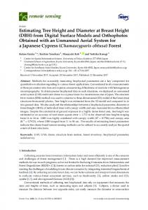
In addition, a GEO SAR has curved trajectories due to its high orbit and the effects of Earth rotation [18–20]. Figure 1a gives the nadir-point trajectories of LEO SAR (ERS-2) and GEO SAR. It can be shown that GEO SAR has a curved trajectory for imaging, rather than the straighter trajectory in LEO SAR. In the presence of impacts of perturbation and curved trajectories, the repeated trajectories of GEO InSAR are un-parallel (the corresponding nadir-point trajectories are given in Figure 1b). Especially at the perigee and the apogee, the trajectories have large curvatures; thus, the un-parallelism of the repeated trajectories is more serious. The 3D sketch map of GEO InSAR repeated trajectories is shown in Figure 1c. A yellow solid line and a blue solid line present the un-parallel repeated tracks of GEO SAR. In this case, if the GEO InSAR data are obtained under the ZDC data acquisition geometry, the obtained sub-apertures for the imaging and InSAR processing are marked in red color. M and S represent the data acquisition positions of the master and slave images based on ZDC, respectively. B is the baseline; Ba is the along-track baseline; BI is the interferometric baseline; and Bp is the perpendicular baseline. is the look angle. Because of the un-parallel GEO InSAR tracks, the obtained InSAR pair based on ZDC has an azimuth wave vector difference κ , and the obtained InSAR pair has a rotation angle in azimuth shown as:
arccos κ, rˆA
(1)
Remote Sens. 2015, 7
13371
where rA is the ground projection vector of azimuth direction and ^ stands for the unit vector. 60°N
60°N
Apogee
Apogee
30°N
30°N
0°
0°
30°S
60°S
30°S
0 1000 Kilometers
N
Perigee
90°E
60°S
120°E
(a)
0 1000 Kilometers
N
Perigee
90°E
120°E
(b) GEO SAR track1
Ba
BI
M
Zero-Doppler position at track 1 Sub-aperture in track 1
B
S Sub-aperture in track 2
Zero-Doppler position at track 2
Bp
GEO SAR track 2
(c) Figure 1. (a) Nadir-point trajectories of ERS-2 (red) and GEO SAR (yellow); (b) nadir-point trajectories of GEO InSAR repeated trajectories (the red line is the first track, and the yellow one is the second track after ten days); (c) three-dimensional (3D) sketch map of GEO InSAR repeated trajectories. This bias makes the InSAR pair have an obvious spatial spectral shift in azimuth a , which is shown in Figure 2. The shift a causes a rotation-induced decorrelation in the interferogram. The rotation-induced decorrelation r is given as: r
ka () Wga
(2)
Remote Sens. 2015, 7
13372
where ka is the spatial spectral shift in the azimuth and Wga is the spatial spectral bandwidth in the azimuth.
ka
Spatial spectrum of track1 Spatial spectrum of track2
Wga
O
a
kr
Figure 2. Two-dimensional (2D) spatial spectra of the GEO InSAR pair. ka is the spatial frequency in the azimuth direction, and kr is the spatial frequency in the range direction. Table 3 shows the correlation coefficient due to the rotation-induced decorrelation of the InSAR pair obtained by different satellites with different time intervals based on the ZDC data acquisition. For GEO SAR, the correlation coefficient decreases to approximately 0.85 when the time interval is one day. With the increasing of the time interval, the correlation coefficient will be worse. It will be less than 0.6 when the time interval is five days. Comparatively, the rotation-induced decorrelation is negligible in a LEO SAR case, such as the TerraSAR-X, because their repeat tracks are nearly parallel. Moreover, the un-parallel tracks make the GEO InSAR pair have a large along-track baseline (Table 3), which means that the length of the interferometric baseline cannot be approximated with the length of the perpendicular baseline in the height retrieval. The perpendicular baseline is dependent on both the look angle and the rotation angle in azimuth . Thus, the perpendicular baseline length is sure to have a bias with respect to the true interferometric baseline length. Table 3. Correlation coefficient due to the rotation-induced decorrelation and the baseline analysis of GEO SAR (perigee) and TerraSAR-X (Track 57, Frame 9242, and Track 57, Frame 9409) under the zero-Doppler centroid (ZDC) data acquisition. Satellite GEO SAR TerraSAR-X
Correlation Coefficient due to the Rotation-Induced Decorrelation
Baseline Length (m)
Along-Track Baseline Length (m)
0.849 (one-day interval ) 0.523(five-day interval) 0.973(eleven-day interval )
13,600 61,600 314
13,500 61,500 62
2.2. Squint-Looking Mode of GEO InSAR Generally, spaceborne SAR systems need attitude control to compensate for the effects of Earth’s rotation, so that the squint angles can be eliminated, which can make the imaging easier and of a high quality. Being impacted seriously by the Earth’s rotation, GEO SAR works in a significant squint-looking mode, resulting in the large Doppler centroid shifts (see the blue line in Figure 3) and the degraded azimuth resolution performance. Total zero Doppler steering is not an optimal option for a GEO SAR system. Under the total zero Doppler steering, the azimuth ground resolution deteriorates
Remote Sens. 2015, 7
13373
seriously, and the yaw angles are too large to be implemented [31]. Nevertheless, under the optimal resolution steering, the GEO InSAR system also works in a slightly squint-looking mode and has Doppler centroid shifts (see the green line in Figure 3). Only at the orbit positions near the perigee and apogee does the zero-Doppler centroid exist.
Doppler Centroids(Hz)
3000 2000 1000
perigee
0
apogee
-1000 -2000
No Steering Optimal Resolution Steering
-3000 -90
0
90 True Anomaly(deg)
180
270
Figure 3. Doppler centroid shifts along the GEO SAR track. As the InSAR height retrieval depends on the geometric relationship, the GEO InSAR height retrieval is impacted by the squint-looking mode. The LEO InSAR height retrieval model includes the range-Doppler localization equations in broadside imaging and phase Equations (2) and (3), which are given by:
R M ,P R M ,Q 2 2 Localization equations in broadside imaging f dc 0 4 h t R M ,P R S ,P 2 Phase equation P sin R M ,P 2 0 Perpendicular baseline
(3)
where R M ,P and R M ,Q are the range vector from the zero-Doppler position to the target P and its ˆ corresponding ground projection with respect to the first track Q , respectively, f dc 2 v M,P , R M ,P
is the Doppler centroid, v M ,P is the velocity vector at the zero-Doppler position in the first track, is the wavelength, t is the interferometric phase only related to the terrain, 0 is the local incidence angle and h is the height of the target with respect to the reference surface. The operators 2 and stand for the norm and inner product, respectively.
P
represents the operator of the
perpendicular baseline. For GEO SAR orbital positions where large Doppler centroid residuals exist (such as when the GEO SAR satellite is above the Equator), searching for the positions of zero-Doppler centroids fails; thus, the employment of the localization equations in the broadside imaging geometry will make a target P in the generated DEMs have the localization error ε , which is shown as:
ε P R M0 ,P 2 , f dc 0 P R M,P 2 ,0
ˆ M ,P where R M0 ,P is the range between M and P at the aperture center moments, f dc 0 2 v M0 , R 0
(4) is
the Doppler centroid at the aperture center moment and v M0 is the velocity vector of the GEO SAR at
Remote Sens. 2015, 7
13374
the aperture center moment in the first track. Therefore, the squint-looking mode has to be specially considered in the GEO InSAR height retrieval. As there exists non-zero-Doppler centroids along the full aperture in most parts of the track (see the green line in Figure 3), the ZDC data acquisition is often impossible in the GEO InSAR system. 3. Optimal Data Acquisition and Height Retrieval Considering the special issues of un-parallel repeated tracks and the squint-looking mode in GEO InSAR, a novel OMRD data acquisition method and a GEO InSAR height retrieval model are proposed in this section to address the issues. In order to demonstrate the issues conveniently, GEO InSAR geometry is introduced firstly in Figure 4. M and S represent the satellite positions of GEO InSAR tracks, and R M ,S is their distance vector. P represents a target that has a height with respect to the global ellipsoid, and Q is its geometric projection on the global ellipsoid with respect to the first pass of the InSAR tracks. R M ,P is the distance vector between M and P ; R M ,Q is the distance vector between M and Q ; R S ,P is the distance vector between S and P ; R S ,Q is the distance vector between S and Q . l is the distance vector from P to Q . v M and v S are the velocity vectors of the GEO SAR in the first track and the second track, respectively. rˆR is the project unit vector corresponding to the range direction unit vector ςˆ with respect to the tangent plane of the global ellipsoid, and rˆp represents the
perpendicular direction of rˆR . xˆ is the azimuth direction vector. h is the height of the target with ˆ is the height direction unit vector. respect to the global ellipsoid, and H
vS
S R M ,S M
vM RS,P
ˆ xˆ H
RM,P rˆP R M ,Q R S ,Q P l h Q Scene
ςˆ
rˆR
Figure 4. Sketch map of the GEO InSAR geometry.
Remote Sens. 2015, 7
13375
3.1. OMRD Data Acquisition Method The data acquisition of the repeat-track GEO InSAR is a process of the sub-aperture selection, and it is realized by determining of sub-aperture center moments. The sub-aperture center moment in the first track is determined by the observation moment of the scene of interest, and the corresponding sub-aperture is obtained according to the length of the integration time. Nevertheless, the selection of the sub-aperture center moment and the related sub-aperture in the second orbit is vital, because it determines the quality of the produced InSAR pair. Because the obtained GEO InSAR pair based on the ZDCs has serious rotation-induced decorrelation, the OMRD data acquisition method is induced to deal with the issue in the following part. In InSAR, the correlation coefficient is mainly affected by several factors [6] as:
the g t
(5)
where the is the thermal noise decorrelation, g is the geometric decorrelation and t is the temporal decorrelation. Because g is mainly impacted by data acquisition methods, it is studied in detail. Based on the basic concept of wavenumber domain analysis in [2], g is expressed as:
g
exp( j) 0 (r ) exp 2 j (κ M κ S ), r
V
(r) h u(u
0
mc
), t R M0 ,P
V
h u (umc ), t R M0 ,P
2
h u(u
(r) h u(u 0
*
sc
sc
2
2
dV ''
), t R S0 ,P
), t R S0 ,P
2
2
dV
(6) '
2
dV
V
where r represents the surface scatter unit, 0 (r) is the surface backscatter coefficient, V represents the integral unit, R S0 ,P is the range between S and P at the aperture center moment, u and t are the azimuth time and the range time, respectively, umc and usc are the positions of targets at the aperture center moments of the InSAR pair, h and h are the impulse response functions of the InSAR system and is the interferometric phase. κ M and κ S are wave vectors, which are expressed by:
R M0 ,P κ M 0 R M0 ,P 2 κ S 0 R S0 , P R S0 , P 2 assuming that the GEO InSAR system works in a fixed center carrier frequency, 0 For simplicity, from Equations (6) and (7) (see the Appendix for details), we have:
(7)
2 .
Remote Sens. 2015, 7
13376 0 exp( j ) 0 (r ) exp 2 j xˆ x ςˆ R M0 ,P V 2 g 2 '' 0 (r) h u(umc ), t R M0 ,P 2 dV
V
h u (umc ), t R M0 ,P
2
h u (u *
sc
), t R S0 ,P
0 (r) h u (usc ), t R S0 ,P
2
2
dV
(8)
'
2
dV
V
where xˆ and ςˆ are spectral shifts in the range and azimuth respectively, which can be expressed as: 1 ˆ C1 R M0 ,S0 , vˆ M0 ξˆ A1 R M0 ,S0 , ˆl B1 R M0 ,S0 , ψ D1 squint looking mode term int erferometry baseline term
1 xˆ E2
(9)
ˆ S ,P , v B2 R M ,S , ˆl C2 R M ,S , ψ ˆ R ˆ D2 R M0 ,S0 , vˆ M0 A2 R M0 ,S0 , ψ 0 0 0 0 0 Coupling term unparallel track term Squint looking mode term
(10)
Variables A1 to D1 and A2 to E2 only depend on the GEO InSAR geometry and can be expressed as: A1 B 1 C1 D1
A2 B 2 C2 D2 E 2
rˆR , ˆl ˆ S ,P , vˆ M R 0 0
Rˆ
M 0 ,P
ˆ rˆR , vˆ M0 rˆR , ψ
, vˆ M0
ˆ S ,P , ψ ˆ rˆR , ψ ˆ rˆR , vˆ M0 R 0
rˆ , vˆ R
M0
(11)
ˆ S ,P , vˆ M0 1 R 0
ˆ M ,P , rˆR R 0
ˆ M ,P , ψ ˆ rˆp , vˆ M0 R 0 rˆp , ˆl
rˆ , ψˆ Rˆ rˆ , vˆ Rˆ p
p
M0
M 0 ,P
ˆ ,ψ
M 0 ,P
, vˆ M0
ˆ S ,P , ψ ˆ M ,P , ψ ˆ 1 R ˆ rˆp , vˆ M0 R 0 0
ˆ S ,P , vˆ M 1 rˆp , ψ ˆ R 0 0
ˆ S ,P , ψ ˆ R 0
ˆ S ,P , vˆ S R 0 0
ˆ M ,P , vˆ M R 0 0
(12)
rˆp , vˆ M0
where vˆ S0 is the velocity at the aperture center moment in the second GEO SAR track, v is the vector ˆ is determined by difference of v M0 and vˆ S0 , R M0 ,S0 is the vector difference of R M0 ,P and R S0 ,P and ψ the cross product of the orthonormal basis ˆl and vˆ M . 0
According to Equation (9),
A1 R M0 ,S0 , ˆl
relates to the interferometric baseline and
ˆ C1 RM0 ,S0 , vˆ M0 depends on the squint-looking mode. As for Equation (10), xˆ is B1 RM0 ,S0 , ψ
Remote Sens. 2015, 7
13377
impacted by many components, including the effects of the un-parallel repeated tracks ˆ S ,P , v , the squint-looking mode B2 R M ,S , ˆl C2 R M ,S , ψ ˆ R ˆ and their coupling A2 R M0 ,S0 , ψ 0 0 0 0 0 term D2 R M0 ,S0 , vˆ M0 . According to Equations (9) and (10), the mismatch of the 2D spatial spectra of the GEO InSAR pair exists if xˆ and ςˆ are not zero, which makes the GEO InSAR pair decorrelate. Thus, g can be expressed as:
g B r
(13)
where B (related to ςˆ ) is mainly induced by the interferometric baseline decorrelation and r (related to xˆ ) is induced by the rotation-induced decorrelation. B should not be eliminated, because the interferometric baseline should not equal zero in the height retrieval. On the basis of the range spatial spectral bandwidth determined by the range bandwidth Wr , the critical baseline Bc , which is the upper limitation of interferometric baseline, is expressed as: Bc R M0 ,S0
ξˆ
2 R M 0 ,P c 0
2
, ˆl .
Wr
(14)
Especially, in the case of the slight squint angle, Equation (14) can be simplified as:
Bc
ˆ M ,P , rˆR R M ,P 2 R 0 0
2
c0 rˆR , ˆl
Wr .
(15)
xˆ is useless for the height retrieval and r should be one for obtaining high coherence.
Conventionally, when the ZDCs are employed, Equation (10) is expressed as: ˆ S ,P , v xˆ R 0
R
M0 ,S0
ˆ 1 . ,ψ
(16)
In LEO SAR, the repeated tracks are nearly perfectly parallel. Thus, v is zero, and xˆ is zero. The spatial spectra of the InSAR pair in the azimuth are coherent, and the minimum rotation-induced decorrelation can be obtained (i.e., r 1 ). However in GEO SAR, the repeated tracks are un-parallel, and the geometry is squint. Thus, v is non-zero, and xˆ is non-zero, if using ZDC data acquisition. In this case, the rotation-induced decorrelation exists (i.e., r 1 ) as the overlapped azimuth spatial spectra of the GEO InSAR pair decrease. By employing the azimuth bandwidth Wa , r is expressed as: r 1
0 v M0
2
xˆ
R M0 ,P 2 Wa
.
(17)
In order to maximize the overlaps of the spatial spectra of the GEO InSAR pair in the azimuth and to minimize the rotation-induced decorrelation, the criterion is proposed to realize the optimal selection of the aperture center moment and the corresponding sub-aperture in the second track. It is given as:
S 0 S 0
0 max r xˆ S
2
(18)
where S 0 is the proper satellite position at the second track, is the azimuth moment of the second aperture and 0 is the aperture center moment of the second sub-aperture.
Remote Sens. 2015, 7
13378
The operation is summarized as follows: Step 1: Based on (18), search the proper satellite position S 0 by the step corresponding to the pulse repeated time along the full aperture of the second track S ; Step 2: Use the determined moment 0 as the aperture center moment of the second sub-aperture; Step 3: According to the integration time Ta , the corresponding sub-aperture of the second track is T T determined as S 0 a , S 0 a . 2 2 Hereby, the GEO InSAR pair is obtained based on (18). Though the Doppler centroid shifts exist, the maximal coherence of the GEO InSAR pair in the azimuth is achieved as the rotation-induced decorrelation is minimized, and the azimuth spatial spectra are coherent. Because of the long full aperture (nearly one thousand seconds for one full aperture) and the relatively limited un-parallelism of the repeated trajectories of GEO SAR, the proposed OMRD data acquisition method can avoid complete azimuth decorrelation in the designing phase. Assuming the observation in the first track is at perigee, it is one of the places with the most serious un-parallel repeated trajectories. The GEO SAR coverage time analysis of a target (78.36°S, 105.58°E) is shown in Table 4 by STK simulations. Since the revisit time of GEO SAR is not exactly 24 hours (3 min 56.4 s bias), the access time in Table 4 is corrected by the bias. It can be shown that the full aperture times of the InSAR pair are overlapped about 739 s (99.6% of the full aperture) in a one-day interval case and about 728 s (98.1% of the full aperture) in a five-day interval case. The full apertures of the InSAR pair will have no common part (giving rise to the complete azimuth decorrelation) after nearly two months. Since the OMRD can work when the full apertures of the InSAR pair have the overlapped part, the GEO InSAR pair with the complete azimuth coherence (the coherent azimuth spatial spectra) can be obtained by the OMRD method when the time interval of the access time is within two months. As for the longer time, station-keeping is needed for GEO SAR. Table 4. GEO SAR coverage time analysis of a target by Systems Tool Kit (STK) simulations (78.36°S, 105.58°E) (30-m diameter antenna). Access Time (day) 1 2 6 31 46 61
Access Start (UTC)
Access End (UTC)
1 September 2015 03:50:12.247 2 September 2015 03:50:14.769 6 September 2015 03:50:28.494 1 October 2015 03:54:49.051 16 October 2015 03:58:49.970 31 October 2015 04:03:49.464
1 September 2015 04:02:34.008 2 September 2015 04:02:36.536 6 September 2015 04:02:50.326 1 October 2015 04:07:10.908 16 October 2015 04:11:11.867 31 October 2015 04:16:11.608
Overlapped Time (s)
Full Aperture (s)
–
741.761
739
741.768
728
741.832
466
741.856
224
741.897
0
742.144
Remote Sens. 2015, 7
13379
After the rotation-induced decorrelation is removed by the OMRD method, the obtained better azimuth coherence will result in lower phase noise and higher height accuracy. If the total coherence raises from 1 to 2 ( 2 is not equal to one because of the and B ), the phase variance in the single-look image pair will decrease by [2,5]: 2 arcsin 1 arcsin 2
2 Li2 1 2 Li2 2 arcsin 1 arcsin 2 2 2 2
2
(19)
where 2 is the decrease of the phase variance and Li2 is Euler’s dilogarithm, defined as:
k
Li2
2
k 1
2k 2
(20)
3.2. GEO InSAR Height Retrieval Model Section 2 presents the characteristics of the GEO InSAR system, including the un-parallel repeated tracks of GEO InSAR, which makes the length of the perpendicular baseline biased with respect to the length of the interferometric baseline and the squint-looking mode in which the GEO InSAR system works in most part of its track. Thus, the height retrieval model in LEO InSAR cannot be adopted in the GEO InSAR height retrieval directly. The localization equations and phase equations can be modified as follows. Localization equations: Since the GEO InSAR system works in the squint-looking mode, the conventional broadside imaging expression of geometric equations in the height retrieval model should be modified according to the squint-looking geometry with respect to the aperture center moment. It is important for avoiding localization errors in the final generated digital elevation model (DEM). Based on the range-Doppler localization [32], the range equation and Doppler equation in the squint-looking mode are expressed as:
R M0 ,P 2 - R M0 ,Q 2 0 ˆ M ,Q 2 vˆ M0 , R 0 f dc
(21)
Phase equation: In the case of the un-parallel tracks, the perpendicular baseline not only depends on the look angle, but also is impacted by the rotation angle in azimuth . Thus, the perpendicular baseline in the phase equation of the conventional height retrieval model needs to be replaced by an accurate expression of the interferometric baseline. After the reference phase removal, the terrain phase T is expressed as: t
4 R M0 , P
2
h R M0 ,S0 , ˆl ˆl, Η ˆ
Differentiating (22) with respect to h , we have:
(22)
Remote Sens. 2015, 7
13380 t 4 ˆ R M ,P h ˆl, Η 0
R M0 ,S0 , ˆl
(23)
2
On the basis of Equation (23), the variation of the interferometric phase is directly related to the baseline component R M0 ,S0 , ˆl . Thus, R M0 ,S0 , ˆl is the accurate expression of the interferometric baseline in GEO InSAR, and it should be used to replace the perpendicular baseline in the phase equation of the GEO InSAR height retrieval model. The GEO InSAR height retrieval model is given as: R M0 ,P 2 R M0 ,Q 2 Localization equations in the squint-looking mode ˆ M ,Q 2 vˆ M0 , R 0 f dc 4 h t R M0 ,S0 , ˆl Phase equation ˆl , Η ˆ R M0 ,P 2 Interferometric baseline
(24)
When the InSAR system works in the broadside imaging and has parallel repeated tracks, R M0 ,S0 , ˆl is equivalent to the perpendicular baseline. 4. Simulations and Discussions In this part, simulations are conducted to verify the proposed OMRD data acquisition method and the GEO InSAR height retrieval model. The inclined curved “figure eight” GEO SAR orbit is utilized in the simulations [17,18]. GEO SAR system parameters are listed in Table 5. The optimal resolution steering is applied [31]. The experimental scene size is 3.5 km × 3.5 km (a relative small scene scope only for the algorithm verification and a higher calculation efficiency), including a 260-m pyramid-like terrain variation. The bandwidth and the integration time are 18 MHz and 120 s to obtain about 20-m resolution, both in the range and azimuth directions. The signal-to-noise ratio (SNR) is set as 10 dB in the simulations. The back-projection algorithm is adopted for the GEO SAR imaging. Perigee is used as an exemplary position in the data acquisition method verification due to the seriously un-parallel there, and the satellite position above the Equator is added for the height retrieval model verification because of its obvious squint-looking status of the GEO SAR. Regarding the InSAR height retrieval, we need to ensure a proper interferometric baseline to improve the height accuracy and a short temporal baseline to obtain a good coherence in the interferogram. In Figure 5, the GEO InSAR baseline with respect to the time interval is shown. The baseline increases as the time interval increases. The variation of the interferometric baseline has the same regular pattern. As for a GEO InSAR pair with a small temporal baseline (e.g., one-day time interval at perigee), the interferometric baseline is negligible, and the height accuracy reduces seriously. Thus, we take the GEO InSAR pairs with a five-day time interval as an example to conduct the simulations.
Remote Sens. 2015, 7
13381 Table 5. GEO SAR system parameters.
Parameters Wavelength (m) Semi-major axis (km) Pulse repeated frequency (Hz)
Value 0.24 42,164 150
Parameters Bandwidth (MHz) Eccentricity Revisit time interval (day)
120
Baseline(Km)
1-day 时 间 间interval 隔一天 2-day 时 间 间interval 隔二天 3-day 时 间 间interval 隔三天 4-day 时 间 间interval 隔四天 5-day 时 间 间interval 隔五天
Equator 赤道
100
Value 18 0.07 5
80
60
40
20
0
Apogee 远地点
Perigee 近地点 0
30
60
90
120
150
180
210
240
270
300
330
360
True Anomaly( °) Figure 5. GEO InSAR baseline with respect to various time intervals. 4.1. Verification of OMRD Data Acquisition Method In the simulations, with respect to the same repeated tracks of GEO InSAR, the ZDC data acquisition and the OMRD data acquisition are conducted to obtain the InSAR pair at perigee, respectively. The center point of the scene is used as the target point in the OMRD data acquisition method. Then, the obtained InSAR pairs are used for imaging and co-registering. After co-registrations, coherence maps are generated after a 3 × 3 look averaging. In Figure 6, coherence maps of the GEO InSAR pairs corresponding to two data acquisition methods are shown. Figure 6a is obtained using the ZDC data acquisition method with an averaged coherence coefficient of 0.475. Figure 6b is obtained based on the OMRD data acquisition with an averaged coherence coefficient of nearly 0.9. The sources of decorrelation of the GEO InSAR pairs corresponding to two data acquisition methods are given in Table 6. As for the ZDC data acquisition method and the OMRD data acquisition method, the critical baselines are about 320 km in two cases. According to the analysis of the sources of decorrelation, the interferometric baseline decorrelations are obtained as 0.986 and 0.985 (corresponding to the interferometric baselines of approximately 4.5 km and 4.9 km, respectively), and the correlation coefficients due to the thermal noise decorrelation are almost 0.909. Therefore, on the basis of (5), the correlation coefficients due to the rotation-induced decorrelation in the two data acquisition methods are 0.523 and 0.996, respectively.
Remote Sens. 2015, 7
13382
50
50
0.8
0.8
100
100
200
0.4
250 0.2
300 350
50
100 150 200 250 300 350 Range (Pixel)
Azimuth (Pixel)
Azimuth (Pixel)
0.6
150
0.6
150 200
0.4
250 0.2
300 350
50
100 150 200 250 300 350 Range (Pixel)
(a)
(b)
Figure 6. Coherence maps of the GEO InSAR pairs corresponding to two data acquisition methods: (a) ZDC data acquisition method; (b) optimal minimal rotational-induced decorrelation (OMRD) data acquisition method. Table 6. Sources of decorrelation of the GEO InSAR pairs corresponding to two data acquisition methods. Correlation Coefficient Averaged total correlation coefficient Interferometric baseline decorrelation Thermal noise decorrelation Rotation-induced decorrelation
ZDC 0.475 0.986 0.909 0.523
OMRD 0.891 0.985 0.909 0.996
Based on the theory in Section 3, the rotation-induced decorrelations are derived from the spatial spectral shifts of the InSAR pairs in the azimuth. In Figure 7, the azimuth spatial spectral shifts are 0.0153 m−1 and 3.40 × 10⁻⁷ m−1 for the ZDC data acquisition method and the OMRD data acquisition method, respectively. Because their spatial spectral bandwidth in the azimuth are nearly 0.0326 m−1 (corresponding to the azimuth spectral bandwidth of about 51.28 Hz) in two cases, the azimuth spatial spectral shift of the InSAR pair in the ZDC data acquisition is large compared to the spatial spectral bandwidth in the azimuth, giving rise to the obvious rotation-induced decorrelation. In contrast, the InSAR pair of the OMRD data acquisition method has the almost negligible azimuth spatial spectral shift and rotation-induced decorrelation. Therefore, by the proposed method, the generated GEO InSAR pair has the maximal azimuth coherence. In the proposed simulation, the averaged total coherence coefficient of the GEO InSAR pair increases more than 0.4 compared to that in the ZDC data acquisition method. Because of the improvement of the averaged total correlation coefficient in the proposed case (from 0.475 to 0.891) after the OMRD data acquisition method is applied, the standard deviation of the phase noise reduces about 0.65 rads based on Equations (19) and (20) in a single-look image pair case. Considering the GEO SAR parameters in Table 5 (the interferometric baseline is about 5 km in the proposed case) and Equation (24), we can obtain that the improvement of the height accuracy under the proposed case is more than 40 m, which suggests that our OMRD data acquisition method has a much better performance.
Remote Sens. 2015, 7
13383
Similarly, the OMRD data acquisition method can also raise the deformation retrieval accuracy in GEO D-InSAR processing by improving the coherence of the InSAR pairs and reducing the phase noise level in the corresponding differential interferogram. As for the D-InSAR data with a one-day interval, Figure 8 shows that the accuracy of the deformation retrieval has been improved significantly if the OMRD data acquisition method is applied in D-InSAR data acquisition. Moreover, ignoring the spatial variation of the scene, the Doppler frequencies in different data acquisition methods are given in Figure 9. By using the ZDC data acquisition method, the InSAR pair has no Doppler centroid shifts, while the InSAR pair has the Doppler centroid shifts of nearly 20 Hz by using the OMRD data acquisition method. Combined with the previous analysis of the rotation-induced decorrelation of the two methods, it can be concluded that no Doppler centroid shifts does not mean the maximal overlapped azimuth spatial spectra and no rotation-induced decorrelation under the impacts of un-parallel repeated tracks. Thus, the classical common band filtering in the frequency domain cannot eliminate the rotation-induced decorrelation. Nevertheless, a proper processing in the wavenumber domain, which is similar to the common band filtering, will be an alternative method of the OMRD data acquisition method to improve the azimuth correlation. 4.2. Verification of the GEO InSAR Height Retrieval Model In the simulations for the verification of the height retrieval model, the OMRD data acquisition method is utilized for the data acquisition. After obtaining the GEO InSAR pairs by the OMRD data acquisition at perigee and above the Equator, the normal interferometry processing, including co-registration and flat Earth removal, is conducted until the height retrieval. Then, DEMs are generated based on the conventional model and the new model separately. The reference DEMs, the generated DEMs based on the conventional height retrieval model and the proposed model at perigee and above the Equator are shown in Figure 10. Some evaluation parameters of DEMs are given in Table 7. At perigee, Figure 10c has only a 26-m peak height, about ten-times smaller compared to that in Figure 10a. This is mainly because the repeated GEO InSAR tracks are un-parallel; thus, the perpendicular baseline length (48.1 km) used in the conventional height retrieval model has a large bias with respect to the true interferometric baseline length (4.9 km). Meanwhile, as the retrieved height is utilized for the iteration operation in localization, the height retrieval errors will lead to localization errors, showing that the peak point of the pyramid is moving to the north of the scene about 0.005 degrees. In Figure 10d, the geometric positioning error is intolerant at the satellite position above the Equator. After the geocoding, latitude localization errors of more than 10 degrees and longitude localization errors of about 30 degrees emerge, and the retrieved height information is distorted into a line-like area. These effects are caused by the failure of the convergence of the iteration in the broadside imaging localization equations, because there exists no zero-Doppler frequencies for the targets along the GEO SAR full apertures above the Equator. Since the GEO InSAR height retrieval model ensures the correct expression of localization equations and the interferometric baseline length, Figure 10e and Figure 10f are almost the same as Figure 10a,b, both in height and localization. Their height error maps are shown in Figure 11, and the related RMSEs of the height are 2.12 m and 0.99 m, respectively. Generally, the height retrieval accuracy highly relates to the length of the interferometric baseline [12]. As the length of the interferometric baseline of the
Remote Sens. 2015, 7
13384
InSAR pair at the satellite position above the Equator is 22 km, which is larger than that at perigee (4.9 km), the height retrieval accuracy of the GEO InSAR pair at the satellite position above the Equator is better than that at perigee.
Shift
Figure 7. Azimuth spatial spectral shifts corresponding to two data acquisition methods. -3
-3
x 10 4
x 10 0
N
78.35
-1
N
78.35
2
-2 -3 S) Latitude(°
S) Latitude(°
78.355
-4 78.36
-5 -6
78.365
78.355
0
78.36
-2
78.365
-4
-7 78.37 78.375 105.52
105.54
105.56
105.58
105.6
105.62
500 Meters 105.64
-6
78.37
-8
0
0
-9
78.375 105.52
(m)
105.54
105.56 105.58 105.6 Longitude(°E)
Longitude(°E)
(a)
500 Meters 105.62 105.64
-8
(m)
(b) -3
N
78.35
-3
x 10 1
x 10
0
N
78.35
2
-1
-3
78.36
-4 78.365
-5 -6
78.37
0 78.375 105.52
105.54
105.56
105.58
105.6
105.62
500 Meters 105.64
1
78.355
-2
S) Latitude(°
S) Latitude(°
78.355
0 78.36 -1 78.365
-2 -3
78.37
-7
0
78.375
-8
3
(m)
105.52
Longitude(°E)
105.54
(c)
105.56 105.58 105.6 Longitude(°E)
500 Meters 105.62 105.64
-4 -5 (m)
(d) -4
x 10
N
78.35
5 0
S) Latitude(°
78.355 -5 78.36 -10 78.365 -15 78.37 -20
0
78.375 105.52
105.54
105.56 105.58 105.6 Longitude(°E)
500 Meters 105.62 105.64
-25 (m)
(e) Figure 8. (a) Reference deformation map; (b) obtained deformation map (ZDC data acquisition method); (c) obtained deformation map (OMRD data acquisition method); (d) deformation error map (ZDC data acquisition method) (root mean square error (RMSE) = 0.0016 m); (e) deformation error map (OMRD data acquisition method) (RMSE = 0.0009 m).
Remote Sens. 2015, 7
13385
Shift
No Shift
(a)
(b)
Figure 9. Doppler frequencies in two data acquisition methods: (a) ZDC data acquisition method; (b) OMRD data acquisition method.
N
250
250
N
78.35
11.8
Latitude (°S)
150 78.36 100
78.365
200
Latitude (°N)
200 78.355
50
78.37 78.375 105.52
105.56 105.6 Longitude (°E)
0 500 Meters
0
105.64
(m)
11.805 150 11.81 100
11.815
50
11.82 11.825 139.08
(a) N
25
26.84
20
26.85
15 78.36 10
78.365
Latitude (°N)
Latitude (°S)
78.355
105.56 105.6 Longitude (°E)
N 200
26.86
150
26.87 100
26.88
50
26.9
0 500 Meters
0
105.64
(m)
26.91
0 500 Meters
107.62
(c)
107.7 107.66 Longitude (°E)
107.74
0 (m)
(d) 250
250 N
N 11.8
78.35 200 150 78.36 100
78.365
50
78.37 0 500 Meters
78.375 105.52
105.56 105.6 Longitude (°E)
(e)
105.64
0 (m)
200
Latitude (°N)
78.355
Latitude (°S)
0
139.11 (m)
26.89
5
78.37
105.52
139.09 139.1 Longitude (°E)
(b)
78.35
78.375
0 500 Meters
11.805 150 11.81 100
11.815
50
11.82 11.825 139.08
0 500 Meters
139.09 139.1 Longitude (°E)
0 139.11 (m)
(f)
Figure 10. Reference DEMs at perigee (a) and above the Equator (b); generated DEM based on the conventional model at perigee (c) and above the Equator (d); generated DEM based on the proposed model at perigee (e) and above the Equator (f).
Remote Sens. 2015, 7
13386
78.35
5
78.36
Latitude (°N)
Latitude (°S)
11.8
10
78.355
0
78.365
4
11.805
2
11.81
0
11.815
-2
-5
-4
11.82
78.37 78.375 105.52
105.56 105.6 Longitude (°E)
6
N
N
0 500 Meters
-10
105.64
(m)
11.825 139.08
0 500 Meters
139.09 139.1 Longitude (°E)
(a)
-6
139.11 (m)
(b)
Figure 11. Error maps of the generated DEMs based on the GEO InSAR height retrieval model. (a) At perigee; (b) above the Equator. Table 7. Error analysis of the DEMs. Parameters Reference DEMs DEMs based on conventional model DEMs based on the proposed model
Positions
Peak Height (m)
RMS (m)
Perigee Above the Equator Perigee Above the Equator Perigee Above the Equator
260 260 26 233 254 254
– – 76.49 – 2.12 0.99
5. Conclusions In order to address the problems brought by the un-parallel repeated tracks and the squint-looking mode of the GEO InSAR system, this paper proposed a novel optimal minimal rotation-induced decorrelation (OMRD) data acquisition method and a GEO InSAR height retrieval model. The new data acquisition method can eliminate the obvious rotation-induced decorrelation of the GEO InSAR pair, which is brought by the conventional zero-Doppler centroid (ZDC) data acquisition method in GEO InSAR pair generation. Moreover, height retrieval errors and localization errors can be avoided by employing the proposed GEO InSAR height retrieval model instead of the conventional height retrieval model with the approximate expression of the interferometric baseline length and the broadside imaging geometry. Under a group of typical GEO SAR parameters, verification is carried out by computer simulations. According to the results, the OMRD data acquisition method is effective for improving the averaged correlation coefficient of the InSAR pair with a significant boost of more than 0.4. Moreover, height errors of hundreds of meters and localization errors of more than 10 degrees can be removed by employing the proposed GEO InSAR height retrieval model. Finally, the generated DEMs can achieve a height accuracy of better than 3 m.
Remote Sens. 2015, 7
13387
Acknowledgements This work was supported by National Natural Science Foundation of China (Grant No. 61225005, No. 61471038, No. 61501032), the Beijing Higher Education Young Elite Teacher Project (YETP1168) and the Chang Jiang Scholars Program (T2012122). Author Contributions The authors, Cheng Hu, Yuanhao Li, Xichao Dong and Teng Long, designed the research, performed data analysis, and contributed with ideas, writing and discussion. Appendix Consider that the following part inside Equations (6) and (7) is used to obtain a simplified expression as:
R R exp 2 j (κ M κ S ), r exp 2 j 0 M0 ,P 0 S0 ,P , r R M0 , P 2 R S0 ,P 2
(A1)
Applying the first-order Taylor series expansion to Equation (A1), we have: ˆ M ,P r, R ˆ S ,P R M 0 ,S0 , R R M 0 ,S 0 , r 0 0 exp 2 j (κ M κ S ), r exp 2 j 0 R M0 , P 2 R M0 , P 2
(A2)
(A3)
ˆ , (A2) can be expressed as: Then, consider that the orthonormal basis ˆl , vˆ M0 and ψ exp 2 j (κ M κ S ), r
R M0 ,P
Rˆ
0
exp 2 j
ˆ M ,P , ψ ˆ R 0
M 0 ,P
, ˆl R M0 ,S0 , ˆl
2
ˆ M ,P vˆ M ˆ R R M 0 ,S 0 , ψ 0 0
R M0 ,S0 , vˆ M0
ˆ S ,P ˆl r, ˆl R ˆ S ,P , ψ ˆ S ,P , vˆ M ˆ r, ψ ˆ R R 0 0 0 0
r, vˆ M0
ˆ r, ψ ˆ R M0 ,S0 , vˆ M0 R M0 ,S0 , ˆl r, ˆl R M0 ,S0 , ψ R M0 ,P
2
r, vˆ M0
ˆ M ,P and ˆl are orthonormal and the baseline length can be negligible compared to the range Because R 0 ˆ M ,P , ˆl R M ,S , ˆl and R ˆ S ,P , ˆl r, ˆl , can be ignored. Consequently, distance, the items, such as R 0
0
0
0
Equation (8) in Section 3.1 can be derived by converting the surface scattering vector r in (A3) to rˆR and rˆP . Conflicts of Interest The authors declare no conflict of interest.
Remote Sens. 2015, 7
13388
References 1. 2. 3.
4. 5. 6. 7.
8. 9. 10. 11. 12. 13. 14.
15.
16.
17. 18.
Graham, L.C. Synthetic interferometer radar for topographic mapping. IEEE proceedings 1974, 62, 763–768. Bamler, R.; Hartl, P. Synthetic aperture radar interferometry. Inverse Probl. 1998, 14, 1–54. Ferretti, A.; Monti Guarnieri, A.; Prati, C.; Rocca, F.; Massonnet, D. InSAR Principles: Guideline for SAR Interferometry Processing and Interpretation. ESA Publications: Noordwijk, The Netherlands, 2007; pp.11–55. Tofani, V.; Raspini, F.; Catani, F.; Casagli, N. Persistent Scatterer Interferometry (PSI) technique for landslide characterization and monitoring. Remote Sens. 2013, 5, 1045–1065. Hanssen, R.F.; Radar Interferometry: Data Interpretation and Error Analysis. Kluwer Academic Publishers: New York, NY, USA, 2001; pp. 23–60. Zebker, H.A.; Villasenor, J. Decorrelation in Interferometric Radar Echoes. IEEE Trans. Geosci. Remote Sens. 1992, 30, 950–959. Massonnet, D.; Rossi, M.; Carmona, C.; Ardagna, F.; Peltzer, G.; Feigl, K.; Rabaute, T. The displacement field of the landers earthquake mapped by radar interferometry. Nature 1993, 364, 138–142. Forster, R.R.; Jezek, K.C.; Koenig, L.; Deeb E. Measurement of geophysical properties from InSAR wrapped phase. IEEE Trans. Geosci. Remote Sens. 2003, 41, 2595–2604. Eineder, M.; Adam, N.; Bamler, R.; Yague-Martinez, N.; Breit H. Spaceborne spotlight SAR interferometry with terraSAR-X. IEEE Trans. Geosci. Remote Sens. 2009, 47, 1524–1535. Raspini, F.; Moretti, S.; Fumagalli, A.; Rucci, A.; Novali, F.; Ferretti, A.; Prati, C.; Casagli, N. The COSMO-SkyMed constellation monitors the costa concordia wreck. Remote Sens. 2014, 6, 3988–4002. Long, T.; Dong, X.C.; Hu, C.; Zeng, T. A new method of zero-doppler centroid control in GEO SAR. IEEE Geosci. Remote Sens. Lett. 2011, 8, 512–516. Hu, C.; Li, X.R.; Long, T.; Gao, Y.T. GEO SAR interferometry: Theory and feasibility study. In Proceedings of the Radar Conference 2013 IET International, Xi’an, China, 14–17 April 2013. Tomiyasu, K. Synthetic aperture radar in geosynchronous orbit. In Proceedings of the Antennas and Propagation Society International Symposium, Maryland, MD, USA, 15–19 March 1978. Monti Guarnieri, A.; Tebaldini, S.; Rocca, F.; Broquetas A. GEMINI: Geosynchronous SAR for earth monitoring by interferometry and imaging. In Proceedings of the IEEE International Geoscience and Remote Sensing Symposium, Munich, Germany, 22–27 July 2012. Prati, C.; Rocca, F.; Giancola, D.; Monti, A. Passive geosynchronous SAR system reusing backscattered digital audio broadcasting signals. IEEE Trans. Geosci. Remote Sens. 1998, 36, 1973–1976. Ruiz-Rodon, J.; Broquetas, A.; Makhoul, E.; Monti Guarnieri,, A.; Rocca F. Nearly zero inclination geosynchronous SAR mission analysis with long integration time for earth observation. IEEE Trans. Geosci. Remote Sens. 2014, 52, 6379–6391. Bruno, D.; Hobbs, S.E.; Ottavianelli, G. Geosynchronous synthetic aperture radar: Concept design, properties and possible applications. Acta. Aston. 2006, 59, 149–156. Hu, C.; Long, T.; Zeng, T.; Liu, F.F.; Liu Z.P. The accurate focusing and resolution analysis method in Geosynchronous SAR. IEEE Trans. Geosci. Remote Sens. 2011, 49, 3548–3563.
Remote Sens. 2015, 7
13389
19. Wu, X.; Zhang, S.S.; Xiao, B. An advanced range equation for geosynchronous SAR image formation. In Proceedings of the IET International Conference on Radar Systems, Glasgow, UK, 22–25 October 2012. 20. Hu, C.; Liu, Z.P.; Long, T. An improved focusing method for geosynchronous SAR. Adv. Space Res. 2013, 51, 1773–1783. 21. Gao, Y.T.; Hu, C.; Dong, X.C.; Long, T. Accurate system parameter calculation and coverage analysis in GEO SAR. In Proceedings of the European Conference on Synthetic Aperture Radar, Nuremberg, Germany, 23–26 April 2012. 22. Qi, L.; Tan, W.; Lin, Y.; Wang, Y.; Hong, W.; Wu, Y. SAR raw data 2-D imaging model and simulation of GEO CSAR. In Proceedings of the IEEE CIE International Conference on Radar, Chengdu, China, 24–27 October 2011. 23. Madsen, S.N.; Chen, C.; Edelstein, W. Radar options for global earthquake monitoring. In Proceedings of the IEEE International Geoscience and Remote Sensing Symposium, Toronto, ON, Canada, 24–28 June 2002. 24. Monti Guarnieri, A.; Prati, C. ScanSAR focusing and interferometry. IEEE Trans. Geosci. Remote Sens. 1996, 34, 1029–1038. 25. Lopez-Dekker, P.; Prats, P.; De, F.; Wollstadt, S. Demonstration of SAR interferometry under crossing orbits using TerraSAR-X and TanDEM-X. In Proceedings of the IEEE International Geoscience and Remote Sensing Symposium, Vancouver, BC, Canada, 24–29 July 2011. 26. Bara, M.; Scheiber, R.; Broquetas, A.; Moreira, A. Interferometric SAR signal analysis in the presence of squint. IEEE Trans. Geosci. Remote Sens. 2000, 38, 2164–2178. 27. Hobbs, S.; Mitchell, C.; Forte, B.; Holley, R.; Snapir, B.; Whittaker, P., System design for geosynchronous synthetic aperture radar missions. IEEE Trans. Geosci. Remote Sens. 2014, 52, 7750–7763. 28. Ruiz-Rodon, J.; Broquetas, A.; Makhoul, E; Monti Guarnieri, A.; Rocca, F. Geosynchronous SAR focusing with atmospheric phase screen retrieval and compensation. IEEE Trans. Geosci. Remote Sens. 2013, 51, 4397–4404. 29. Wertz, J.R.; Larson, W.J. Space mission analysis and design. Kluwer Academic Publishers: Boston, MA, USA, 1999. 30. Marshall, S.R.; Patrick, R.C. Satellite Tool Kit User’s Manual: Intuitive Satellite Systems Analysis Software Design to Assist in Visualizing and Analyzing Complex Relationships in Space Systems. Analytic Graphics, Incorporated: Exton, PA, USA, 1997. 31. Zhang, Q.J.; Yin, W.; Ding, Z.G.; Zeng, T.; Long, T. An optimal resolution steering method for geosynchronous orbit SAR. IEEE Geosci. Remote Sens. Lett. 2014, 11, 1732–1736. 32. Curlander, J.C. Location of spaceborne SAR imagery. IEEE Trans. Geosci. Remote Sens. 1983, 20, 359–364. © 2015 by the authors; licensee MDPI, Basel, Switzerland. This article is an open access article distributed under the terms and conditions of the Creative Commons Attribution license (http://creativecommons.org/licenses/by/4.0/).