Dec 21, 2010 - Preliminary (trial) numerical analysis can also be performed on 1D models .... [2] A. Nagode, L. Kosec, B. Ule, Engineering Failure. Analysis, 18 ...
ISSN 0543-5846 METABK 51(1) 113-116 (2012) UDC – UDK 669.14.018.298:669.18=111
D. KOVAČEVIĆ, M. SOKOVIĆ, I. BUDAK, A. ANTIĆ, B. KOSEC
OPTIMAL FINITE ELEMENTS METHOD (FEM) MODEL FOR THE JIB STRUCTURE OF A WATERWAY DREDGER Received – Primljeno: 2010-12-21 Accepted – Prihvaćeno: 2011-03-10 Preliminary Note – Prethodno priopćenje
This paper is presentation of the development of advanced approach for modeling and structural analysis of jib structure which is usually part of waterway bucket dredgers. Object of analysis is a jib structure which will be reconstructed for the excavation of grain material from a river bed. Main goal of paper is to proof benefits of enough sophisticated i.e. “optimal” FEM model for structural analysis of this type of structures in comparison with simple, but not adequate models. Proper stress state is emphasized as primary, but not only condition. It is necessary to reach serviceability and durability state, as well as affordable financial construction circumstances. Key words: FEM modeling, jib, special FE, nonlinear analysis Optimalni model metode konačnih elemenata (MKE) konstrukcije strijele plovnog bagera. Rad je kratki prikaz razvitka naprednog pristupa u modeliranju i strukturnoj analizi konstrukcije strijele, koja je uobičajeni dio plovnih bagera. Predmet analize je konstrukcija strijele bagera vedričara rekonstruisanog za iskop šljunka sa dna vodotoka. Cilj rada je da dokaže prednosti dovoljno sofisticiranog tj. “optimalnog” MKE modela za analizu ovog tipa konstrukcija u odnosu na jednostavne, ali neodgovarajuće modele. Odgovarajuće naponsko stanje je istaknuto kao primarni, ali ne i jedini uvjet za rabljenje bagera. Potrebno je osigurati i odgovarajuće stanje upotrebljivosti i trajnosti, kao i povoljne ekonomske uvjete izrade konstrukcije. Ključne riječi: MKE modeliranje, strijela, specijalni KE, nelinearna analiza
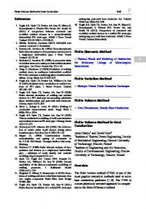
INTRODUCTION The jib of the dredger (Figure 1) should satisfy several opposed requirements and its structure is a result of, in an engineering sense, one compromise solution. Load capacity is its main characteristic - it prevents failure, as well as yield limit state. Another requirement is the jib’s buckling stiffness. Occurrences of local loss of stability are possible, bearing in mind that this is a thin-walled steel plate structure. Serviceability provides conditions for the real exploitation of a machine. It is provided by sufficient structure stiffness and allows uninterrupted operation. Durability in terms of functionality is a requirement to maintain serviceability during a needed time span [2]. The already listed requirements are opposed to the requirement for the low mass of jib structure which should provide maneuverability during exploitation and maintenance, as well as the energy efficiency of the dredger. In order to meet the cost efficiency demands, there is also a requirement for the jib structure to be as simple as possible, with minimum input of steel. A critical stage in the process of meeting the listed requirements is the selection of the structure system, with a detailed design. The next stage is the selection of D. Kovačević, I. Budak, A. Antić, Faculty of Technical Sciences, University of Novi Sad, Novi Sad, Serbia., M. Soković, B. Kosec, Faculty of Natural Sciences and Engineering, University of Ljubljana, Ljubljana, Slovenia.
METALURGIJA 51 (2012) 1, 113-116
Figure 1 Dredger with jib structure [1]
a reliable numerical model with a capacity for a real simulation of the structure behavior in various conditions, which represents the main subject of this paper. There is a relative sparseness of papers which deal with FEM analysis of this type of structure [3-5]. Their primary feature is the use of complex FEM models to analyze critical structure components. This very feature has provided a primary motivation for the authors of this paper to look into alternative ways of advanced modeling of jib structure.
POSSIBLE NUMERICAL MODELS FOR JIB STRUCTURE ANALYSIS Waterway dredger jib is a spatial structure with a pronounced longitudinal dimension. It is made of steel thin 113
D. KOVAČEVIĆ et al.: OPTIMAL FINITE ELEMENTS METHOD (FEM) MODEL FOR THE JIB STRUCTURE OF A WATERWAY...
plates of various thicknesses with strengthening parts which increase load capacity and stiffness. Preliminary (trial) numerical analysis can also be performed on 1D models with beam FE. However, only 2D models with surface FE meet the requirements of development research. Due to existence of zones with a relatively high thickness of plating, it is necessary to use finite elements which conform to Reissner- -Mindlin plate theory (given in more detail in [6, 7]). Provided that the occurrence of “shear-locking” phenomenon is avoided, such finite elements perform very well in comparison with other conventional surface finite elements which are based on Kirchof’s assumptions. A simple benchmark test can illustrate the advantages of model which uses 2D FE, in comparison with 1D FE model. For a vertical, uniform load, a 1D model composed of beam FEs, and a 2D model using quadrilateral shell (isoparametric, nine- -node, heterosis) Fes, yield quite different information on the structure behavior. As regards the more precise 2D model, principal stresses are 1,75 to 11,75 times higher than those obtained by the simpler 1D model. Similarly, vertical displacements differ by factors 1,54 to 1,80 than the 2D model. In addition, for an eigenvalue shape with horizontal displacements, the lowest eigenvalue frequency of the 1D model is 1,8 times lower than that of the 2D model. This benchmark test provided significant information on the critical aspects of structure behavior, and certainly justified the application of the more complex model. With this in mind, all further considerations shall pertain to the numerical model of the jib which uses 2D shell finite elements. It is important to note that in order for the jib to meet the serviceability requirements, the stiffness of jib (especially its bending strength in horizontal plane, and torsion strength) should remain within the limits which provide proper functioning of the chain-bucket system. In other words, the possibility of chain sticking due to large flexion and/or torsion deformations of structure should be prevented. Wrong perception of stiffness, due to application of inappropriate model, can cause problems which are difficult or even impossible to rectify later on in the process. AxisVM®, release 10.2f, according to [8], was used to model the jib.
MODELING OF THE JIB STRUCTURE TOPOLOGY AND GEOMETRY To create the geometric model of the jib structure (Figure 2) a non-automated approach was used to generate FE mesh, with the goal to minimize the number of FE, and enhance the efficiency of analysis. Additional advantage of this approach is predominance of the quadrilateral shape of FEs, avoiding large FE shape distortions, which contributes to minimization of errors. 114
Figure 2 Topology of the jib structure model
MODELLING OF ELEMENTS, BOUNDARY CONDITIONS AND ACTIONS The presented concept for defining geometry and topology resulted in a numerically robust, efficient, and rational model with 6525 nodes, 7188 shell FEs, and 140838 DOFs. Structure elements were approximated with quadrilateral shell FEs (heterosis type) with nine nodes, and triangular FEs with seven nodes, based on ReisnerMindlin and the membrane stress state theory. Each node of this element has six degrees of freedom – three translations and three rotations. It should be noted that the rotational degree of freedom in the FE plane (the so called “drilling” DOF) was introduced implicitly, which is usual approach. The next step requires higher degree of creativity from the design engineer, and pertains to modeling of support zones of the structure system, the spots of abrupt change of stiffness with eccentricity, as well as the spots where construction elements are connected in a specific way. It is customary in FEM modeling to perform this by defining the boundary and interface conditions [9,10]. The jib-axle connection demands a special approach. More precisely, it is necessary to model an almost entirely free rotation (with little friction) of jib about the axle, and to disable jib movement about the axle in radial and tangential directions, as well as alongside the axle. This was done using the link-type FEs (more detail in [11]). The link FEs allow modeling of links and connections with special characteristics. If the connection between two adjacent FEs is such that there are no mutual nodes, a link FE is used. By changing the stiffness and location parameters of the so-called “interface point”, a number of various connections can be modeled. Link FEs were used in two cases of modeling jib structure: to define the axle-jib connection, and a large number of eccentric connections between plates of jib plating. The jib-axle connection is a cylindrical hinge (Figure 3) which only allows rotation about the Y-axis of the global coordinate system. Shown in Figure 4 is a model of that hinge with the disposition of link FEs. As can be seen, the link FEs allow radial connection between a node on the axle and the appropriate nodes on the shell FE of the jib hinge. METALURGIJA 51 (2012) 1, 113-116
D. KOVAČEVIĆ et al.: OPTIMAL FINITE ELEMENTS METHOD (FEM) MODEL FOR THE JIB STRUCTURE OF A WATERWAY...
Figure 5 Jib’s displacements in y-direction
Figure 3 Hinged support zone of the jib
Figure 6 Jib’s principal stresses distribution
Figure 4 Link FEs in the hinged support zone
Of the six parameters which define stiffness of the link FE, only the one which pertains to rotation about the global Y axis is set to zero, which defines an ideal, frictionless rotation. All other parameters are set to values which indicate friction, flexural/axial stiffness (see [12] for details). In this way, a simple and sufficiently accurate model of this connection is obtained. Any other alternative approach to modeling should lead to occurrence of parasite stresses which do not represent the real behavior of support. Similar applies to all other eccentric connections between the thin plates or the rib, if they are of different thickness. Here, all the six parameters of stiffness are of non-zero value which simulates a welded eccentric connection. Such model configuration of eccentrically welded thin plates is necessary, especially in cases of large shell stresses.
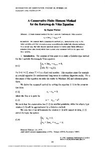
centrated forces were replaced with continuous load (which corresponds to the character of real loads) in order to avoid stress concentration due to large concentrated forces. Regards to displacement criterion, the referential jib configurations are at 18º and 45º to horizontal. Table 1 gives maximum displacements in the jib’s local coordinate system and Figure 5 gives displacements in the ydirection. According to principal stresses, the referential jib configuration is at 18º. Shown in Figures 6-8 is the distribution of principal stresses in the zone of jib bottom support. Table 1 Maximum jib displacements
18º
x-direction /mm 44,6≈L/1098
y-direction /mm 71,6
z-direction /mm 48,7
45º
12,5
112,5≈L/435
52,3≈L/937
Because of a large volume of results (principal stresses in the two directions for top/bottom plate zones, for two configurations) as well as a large number of FEs, here are shown only the zones with exceeded the allowed stress (16,0kN·cm-2) for the two configurations (hatched areas in the diagrams).
ANALYSIS OF THE JIB STRUCTURAL RESPONSE Characteristic configurations of the jib are: position for repair, position for transport, and the three positions for dredging. Eight load combinations were considered, and referential configurations and load combinations were determined. Load values were adopted based on the project data, and design regulations which are used in this area. ConMETALURGIJA 51 (2012) 1, 113-116
Figure 7 Support external zone stresses
115
D. KOVAČEVIĆ et al.: OPTIMAL FINITE ELEMENTS METHOD (FEM) MODEL FOR THE JIB STRUCTURE OF A WATERWAY...
REFERENCES [1]
Figure 8 Support internal zone stresses
It should be emphasized that the excessive stress in the jib support area which is in contact with the river bottom is primarily due to simplification of the numerical model which represents this part of the jib structure. More precisely, it is justified to assume that the equipment omitted from this model (drum, axle, aggregate, etc.) would significantly increase both the stiffness and load capacity.
CONCLUSIONS AND RECOMMENDATIONS It is evident from the previous the analysis of the jib, as a highly complex task, requires full attention to be devoted to modeling - not only of the jib structure elements, but also the supports and connections. Especially important for the modeling of connections are the link FEs which allow simulation of almost all boundary and interface conditions. The model at this level of complexity and accuracy, allows a detailed insight into the jib behavior under load. On the other hand, the proposed model and modeling algorithm provide sufficient support for a rational, reliable, robust, and cost-efficient design of this type of structure.
116
D. Kovačević, Numerical analysis and computation of jib structure of waterway bucket dredger - Technical report, Ship Registry of Republic of Serbia, 2009. [2] A. Nagode, L. Kosec, B. Ule, Engineering Failure Analysis, 18 (2011) 1, 61-67. [3] V. D López, Finite Element Crane Analysis According to UNE 58132-2 Standard, University of Carlos III, Madrid, 2008. [4] E. Rusinski, J. Czmochowski, P. Moczko, Journal of Automation in Construction, 17 (2008), 271-277. [5] S. D. Shinde, International Journal of Recent Trends in Engineering, 1 (2009) 5, 145-149. [6] R.D. Cook, Finite Element Modelling for Stress Analysis, John Wiley & Sons, Inc, 1995. [7] D. Kovačević, FEM Modelling in Structural Analysis, Građevinska knjiga, Belgrade, 2006. [8] AxisVM® 10 User’s manual, InterCAD, Budapest, 2009. [9] E. Kormanikova, I. Mamuzić, Metalurgija, 47 (2008) 2, 129-132. [10] B. Kosec, L. Kosec, F. Kosel, M. Bizjak, Metall, 54 (2000) 4, 186-188. [11] D. Kovačević, R.Folić, Some Aspects of FEM Structural Modelling by Link FE, Proceedings of the XI International Conference on Civil, Structural and Environmental Engineering Computing - CC2007, Malta, 2007, 211-226. [12] W.J. Vlasblom, Dredging Equipment and Technology, Ch. 6 - Bucket (Ladder) Dredger, Delft University of Technology, 2004.
Note: The responsible translator for English language is Ognjan Lužanin, Faculty of Technical Sciences, University of Novi Sad, Serbia
METALURGIJA 51 (2012) 1, 113-116