Opportunistic signals, such as WiFi ...... and so on. The particles closer to WiFi or Bluetooth positioning results will ..... (b) The strength heat map of magnetic field.
This article has been accepted for publication in a future issue of this journal, but has not been fully edited. Content may change prior to final publication. Citation information: DOI 10.1109/ACCESS.2018.2868792, IEEE Access
> REPLACE THIS LINE WITH YOUR PAPER IDENTIFICATION NUMBER (DOUBLE-CLICK HERE TO EDIT)
REPLACE THIS LINE WITH YOUR PAPER IDENTIFICATION NUMBER (DOUBLE-CLICK HERE TO EDIT) < outputs from Inertial Measurement Unit (IMU). On one hand, some researches focus on heading estimation under different device carrying modes. On the other hand, some apply Principal Component Analysis (PCA) or enhanced PCA into heading estimation using data from accelerometer and gyroscope [18][22]. In the paper [23], the least-squares linear regression is used to calculate the direction of the horizontal acceleration to determine the walking direction. In this paper, an optimal heading estimation is achieved through three aspects: simplified sensor calibration, heading estimation using projected acceleration along a moving direction, and constrained current environment accessible path. Based on the review of heading estimation, we can see that many researches utilize Kalman filter in pedestrian fusion positioning with multiple sensors and opportunistic signals [24][25]. It is known that Kalman filter is the optimal filter for linear Gauss system [14]. However, in nonlinear PDR system with non-Gaussian noise, its performance will degrade. Therefore, there are researches using particle filter to optimize indoor positioning [26][27]. But using ordinary particle filter (OPF) has a flaw such that it loses diversity of particles as the number of iterations increases. Consequently, this paper proposes a robust modified particle filter algorithm namely Multidimensional Particle Filter (MPF). In an ordinary Particle Filter (OPF), each particle represents a possible 2D position and heading for the user in this PDR approach. Some positions are perhaps more likely than others, so each particle contains a weight value that represents the probability of it being correct based on all the information to date[26]. Unlike OPF, in a MPF, more uncertainties such as 2D coordinates, heading bias, step length parameters, motion state, particle lifetime, and so on, are assembled into a higher dimensional particle. The max number of particles varies with the number of walking steps and the density of walls. Based on the optimized particle filter, the performances of heading estimation and positioning are both improved. In summary, our contributions of this paper include two parts: Firstly, we propose a novel and comprehensive pedestrian indoor positioning solution in which heading estimation is improved by using a simplified magnetometer calibration, by calculating projected acceleration along moving direction using acceleration features in frequency domain, and by applying direction constrains to accessible paths instead of position constrains to free space. Secondly, this paper proposes a high dimensional particle filter namely MPF which includes position, heading, step length parameters, motion label, lifetime, number of current particles, and factor which is a weight depending on external observations. MPF can handle more uncertain parameters compared to OPF. Therefore, positioning with a MPF can achieve lower errors using low quality sensors, mitigate interference introduced from surrounding environments, and reduce heading ambiguities due to different modes of carrying a smartphone. This paper is structured as follows. The optimization of heading estimation is given in Sect. II; multidimensional particle filter positioning is presented in Sect. III; and final conclusion is drawn in Sect. IV.
2
II. THE OPTIMIZATION OF HEADING ESTIMATION
Heading in a PDR algorithm refers to the moving direction of a pedestrian. To obtain an accurate pedestrian heading is one of the major challenges in an indoor positioning system. On one hand, magnetometer is sensitive to metal objects and indoors electromagnetic interference. On the other hand, the accumulated heading drift is unavoidable if angulated integration is applied using gyroscope readings. Currently, the commonly used magnetometer calibration method is to rotate the smartphone around the figure “8”[28]. This methodology is time consuming due to the number of collected samples is generally not enough to calculate a valid calibration model, resulting in failures and reruns. Besides, the smartphone heading estimation is also influenced by the attitude or placement of the phone. Since the heading of PDR represents the walking direction of the pedestrian and not of the phone; any change in the phone placement during walking, calling or swinging phone in hand, will induce wrong moving direction. Some researches compensate the heading offset under different carrying modes by adding fixed heading bias [12][29]. However, a large number of training samples from different people is needed to tune this set of heading bias in order to support diverse use cases. To resolve the heading estimation issues addressed above, we firstly propose a simplified calibration method to optimize magnetometer calibration[36]. Then, a heading estimation algorithm using projected acceleration is introduced to reduce the influences by diverse phone placements. Finally, a constrain method is applied to generate a cleaner heading estimation from the accessible path. A. THE CALIBRATION METHOD FOR SELF-CONTAINED MAGNETOMETER ON SMARTPHONE
Typical magnetometer reading is disrupted by external interference and internal errors [30][31]. Internal errors of a magnetometer sensor caused by the manufacturing process and components quality can be divided into non-orthogonal error, sensitivity error, sensor noise, and zero-offset [36]. Knowing the introduced error and analyzing the error criteria, we can obtain the error model equations of the magnetometer measurement system as follows [32]: (1) B ni ( nm Bc lm ) li w where B is a vector consisting of three values measured from magnetic field. Bc represents real magnetic field vector; ni is a 3-by-3 matrix representing nonlinear system errors including sensitivity error and non-orthogonal error; nm is also a 3-by-3 matrix representing nonlinear error caused by magnetic interference, namely soft-iron effect; lm is a vector representing linear error caused by magnetic perturbation, namely hard-iron effect; li and w represent zero-offset and sensor noise respectively. After merging the similar items, we can get (2), the error model of magnetometer in this paper. (2) B ABc b in which A is a matrix representing multiplicative error and b represents linear errors. After performing a magnetometer calibration, the magnetic
2169-3536 (c) 2018 IEEE. Translations and content mining are permitted for academic research only. Personal use is also permitted, but republication/redistribution requires IEEE permission. See http://www.ieee.org/publications_standards/publications/rights/index.html for more information.
This article has been accepted for publication in a future issue of this journal, but has not been fully edited. Content may change prior to final publication. Citation information: DOI 10.1109/ACCESS.2018.2868792, IEEE Access
> REPLACE THIS LINE WITH YOUR PAPER IDENTIFICATION NUMBER (DOUBLE-CLICK HERE TO EDIT) < field vector which we obtain should be equal to local geomagnetic vector. At this time, we rotate the smartphone randomly in the three-dimensional space to collect magnetic field data. The modulus of the data should be constant, and equal to the value of local geomagnetic field strength B [33]: (3) BcT Bc B2 Combined with (2), we can get: ( B b)T ( A1 )T A1 ( B b) B 2
(4)
3
just one circle of rotation cannot determine the equation as shown in Fig.3. Thus, we need to rotate the smartphone around another axis to get another trace on the surface of the ellipsoid. After we get two circles in two mutually perpendicular planes, we can determine the unique ellipsoid equation. Compared with other methods like six-directional stewing method[15], and ∞ shape method [28] this proposed technique requires fewer data and costs less time with the same calibration effect.
It is noted that the form of (4) is almost equivalent to the ellipsoid equation. Therefore, the errors of magnetometer are distributed on the surface of an ellipsoid. The centre of this ellipsoid depends on hard-iron effect b, and the shape depends 1 T 1 on the symmetric matrix ( A ) A [34]. The difference between the magnetic field vector before and after calibration is shown in Fig. 1. FIGURE 3. The shape of an ellipsoid.
Before calibration
50
Bz(mGauss)
0
-50
After calibration 100
-100
50 0 0 100
-50 200 -100
FIGURE 1. The comparison of magnetic field data before and after calibration [35].
If we collect enough magnetic field data and solve the ellipsoid equation of the distribution of magnetic vector, we can calculate A and b by matrix operation. Moreover, if we compile the minimum data required for calibration purposes, we can design an efficient way to rotate the magnetometer in a smartphone which will collect a small quantity of magnetic field data with enough weight to fulfill our calibration process. With the body coordination system definition of smartphone as shown in Fig.2, we select two of three axes of the magnetometer in the smartphone as the rotational axes. Then we rotate smartphone around these two axes to collect data. Y Z
X
FIGURE 2. The body coordinate system of a smartphone
In principle, after we rotate the smartphone around one axis, we can roughly sketch the shape of the ellipsoid[36]. However
As collecting magnetic field data becomes more efficient, less time is spent on solving the ellipsoid equation calibration process. Therefore, we have specifically made a series of experiments and explored the cost effect to calibrate the smartphone based on different rotation modes. All experiments were conducted in a typical office building. The sensors we used were embedded in a smartphone is AK8963 Magnetometer from Manufacturer AKM with resolution of 0.15 μT/LSB and its sample rate is 100 Hz. The whole calibration process can be achieved both by online and offline. In this paper, we develop an indoor navigation App which performs the calibration process online.
FIGURE 4. The distribution of magnetic field data before/after calibration. The red trace represents the data without calibration. The blue one is the result using calibration matrix proposed in this paper.
First, magnetic field data were collected by rotating the smartphone around X and Z-axis of its coordinate system; quickly followed by the calibration output data. Some example data of our experiment are shown in Fig. 4 and Fig.5. The same data used in Fig.4 and Fig.5 is collected in a typical indoor environment. As shown in Fig.4, the trace after calibration is much closer to the light green sphere skeleton, which is equivalent to lower variance. Fig.5 demonstrates that after calibration the variance of the data is greatly reduced from 134.19 to 0.09 degrees.
2169-3536 (c) 2018 IEEE. Translations and content mining are permitted for academic research only. Personal use is also permitted, but republication/redistribution requires IEEE permission. See http://www.ieee.org/publications_standards/publications/rights/index.html for more information.
This article has been accepted for publication in a future issue of this journal, but has not been fully edited. Content may change prior to final publication. Citation information: DOI 10.1109/ACCESS.2018.2868792, IEEE Access
> REPLACE THIS LINE WITH YOUR PAPER IDENTIFICATION NUMBER (DOUBLE-CLICK HERE TO EDIT)
REPLACE THIS LINE WITH YOUR PAPER IDENTIFICATION NUMBER (DOUBLE-CLICK HERE TO EDIT)
REPLACE THIS LINE WITH YOUR PAPER IDENTIFICATION NUMBER (DOUBLE-CLICK HERE TO EDIT)
REPLACE THIS LINE WITH YOUR PAPER IDENTIFICATION NUMBER (DOUBLE-CLICK HERE TO EDIT) < TABLE III HEADING ERROR ANALYSIS OF NEXUS 5 TESTING RESULTS Item
RMSE/Proposed
RMSE/[29]
Handheld mode Photo mode Calling mode Pocket mode
0.56° 2.32° 8.48° 4.52°
2.56° 7.58° 5.38°
7
remove the shorter line segments that overlap, and merge multiple segments to obtain a continuous line segment. After this simplification process is complete, we end up with the line set as shown in the following Fig.13 (b).
C. HEADING ESTIMATION BASED ON ACCESSIBLE PATH CONSTRAINTS
A priori map can provide constraints on the walking area given pedestrians normally walk in the accessible area of the map[37]. Furthermore, similar to map matching method applied to car navigation, this paper proposes a scheme to constrain pedestrians’ heading by using map matching, that is, extract the valid open space area of the map to form accessible paths information including the setting direction of each road. This will assist heading estimation for our PDR system. Different from the previous graph-based or link-node map matching solutions, we do not need to build the topological relationship for lines. The required structure of accessible path only includes the starting point and end point of each path and the direction of the path because the application of accessible path is mainly to assist the heading estimation. There are also many existing algorithms for accessible path extraction [44]-[46]. In this paper, we use the widely applied indoor floorplan, such as Fig.12 (a) to generate the accessible path.
(a)
(b) (a)
(b)
(c)
FIGURE 12. (a) The indoor map used in this project. (b) The accessible area obtained after image processing. The white area is the area we obtained. (c) The region boundaries (white lines) obtained by edge detection.
Therefore, only the accessible area is needed to be extracted from the indoor map, this will allow us to extrapolate the corresponding accessible path data. This paper uses expansion and corrosion in digital image processing as the main strategy of road extraction. After processing, we can get the rough accessible area as shown in Fig.12 (b). Next, we perform edge detection on the image shown in Fig.12 (b) with Canny operator. The edge image can be obtained as shown in Fig.12 (c). After that, we use Hough Transform to extract the lines in the image, from which we can get the formula of each line in Fig.13 (a). Hough Transform is one of the basic image processing ways to identify geometric shapes. This method has been very effective for segmenting geometric shape with the same characteristics from the image. We can find that there are numerous overlapping lines and very short lines in the set. Therefore, we are required to simplify and reduce the line set. The goal of the simplification is to
(c) FIGURE 13. (a) The line set extracted by Hough Transform. (b) The simplified line set. (c) The accessible path of the indoor map.
Now that we have defined the accessible path constraints for an indoor map, we can apply the accessible path into heading estimation assistance. We propose the following formula to assist heading estimation.
2 R ,i min compass R ,1 , compass R ,2
final
2
where
final
compass
(5)
is the final result of heading estimation, and
2169-3536 (c) 2018 IEEE. Translations and content mining are permitted for academic research only. Personal use is also permitted, but republication/redistribution requires IEEE permission. See http://www.ieee.org/publications_standards/publications/rights/index.html for more information.
This article has been accepted for publication in a future issue of this journal, but has not been fully edited. Content may change prior to final publication. Citation information: DOI 10.1109/ACCESS.2018.2868792, IEEE Access
> REPLACE THIS LINE WITH YOUR PAPER IDENTIFICATION NUMBER (DOUBLE-CLICK HERE TO EDIT)
REPLACE THIS LINE WITH YOUR PAPER IDENTIFICATION NUMBER (DOUBLE-CLICK HERE TO EDIT)
REPLACE THIS LINE WITH YOUR PAPER IDENTIFICATION NUMBER (DOUBLE-CLICK HERE TO EDIT) < recognition probability, when the change of motion state is detected. The motion label assignment will be described in the follow-up sub-section. i Lifetime, tk , is added to give a confidence to a living particle. Longer time a particle lives, higher confidence is given because we believe that the states of a particle with longer life are more reliable compared to the ones with short life. If a particle survives a long time, that is, it does not collide with the walls. It indicates that the particle attributes are similar to the real pedestrian states with a small margin of error. i Factor ck is reserved for weighting particles given opportunistic signal observations Ok such as WiFi, Bluetooth, and so on. The particles closer to WiFi or Bluetooth positioning i results will be given higher ck . i i The particle lifetime tk and the particle factor ck are both set to 1 at initialization. Every time a step event is detected, the lifetime is incremented by one up to a corresponding maximum threshold relative to the original value. The particle factor is assigned by a value between 0 to1 depending on the range from the particle to the opportunistic signal positioning results. The i weight of the particle k is determined by the following expression:
ki cki tki
(11)
In the process of initialization, we add the zero mean Gaussian noise with the proper variance to the coordinates of each particle. Since the PDR system itself is unable to locate the initial position, there are two schemes presented in this paper for tabulating initial point positioning based on the PDR particle filter algorithm: one is user manual setting; the other is absolute opportunistic signal positioning localization. Moreover, to prevent “crossing walls” during positioning, we would make a collision detection between the surrounding walls against the line connecting the pedestrian coordinates and the particle coordinates. An example is shown in Fig. 19.
10
true heading and the PDR system heading estimation.
FIGURE 20. The diagram of particle filter correcting heading estimation. (Green dots: alive; Red dots: dead)
If there is a step event detected by the PDR system, the filter will judge whether each particle is alive. The judgment conditions include map wall collision detection and weight threshold restriction. If a particle does not collide with any walls or weighs higher than a certain threshold, that particle will be added into a live particle set and its lifetime will increase by one, or else it will be added into a dead particle set. We also add a maximum divergence radius to eliminate particles too far from the particle set, which is shown in (13).
Rmax c3 ec4 Nwall Rmin
(13)
where Rmax is the maximum divergence radius and c3 , c4 are constant coefficients. N wall is the number of wall lines around the position of a particle. Rmin is the minimum divergence radius to ensure the most particles to be alive,which depends on the average width of the roads indoors which can be manually set. When resampling the particles, the algorithm would sample the particles’ attributes from the lived particle set, including the coordinates, the heading bias, the step length parameters and factor. The dead particle lifetime is initialized to one after having copied lived particle’s attributes, of which the lifetime decreases by one. The dead particle maintains its number when copying attributes. B. MOTION RECOGNITION ASSISTANCE
FIGURE 19. The diagram of optimized initialization distribution of particle filter. (Green dots: alive; Red dots: dead)
In Fig. 20, bias represents the heading bias of the whole particle set, which can be calculated by (12). k bias
1 N i k N i
(12)
Most of PDR based smartphone indoor positioning systems utilize the heading of the smartphone to represent the heading of the pedestrian, which assumes that the pedestrian moving direction is same as the smartphone’s heading. If the pedestrian rotates the phone in space for taking a photo or for calling, the phone heading estimation will also change even though the movement is kept in the same direction. This would introduce significant heading estimation errors for indoor positioning. Therefore, this paper uses motion recognition to assist particle filter to realize heading estimation and positioning under different phone carrying modes.
The heading bias k of a particle is also initialized by zeromean Gaussian distribution and bias equals to zero. When the heading estimation performs badly in the process of positioning, some particles may die by colliding with the walls, which then allows us to abandon their heading biases. At this time, bias is a non-zero value, which represents the difference between the i
2169-3536 (c) 2018 IEEE. Translations and content mining are permitted for academic research only. Personal use is also permitted, but republication/redistribution requires IEEE permission. See http://www.ieee.org/publications_standards/publications/rights/index.html for more information.
This article has been accepted for publication in a future issue of this journal, but has not been fully edited. Content may change prior to final publication. Citation information: DOI 10.1109/ACCESS.2018.2868792, IEEE Access
> REPLACE THIS LINE WITH YOUR PAPER IDENTIFICATION NUMBER (DOUBLE-CLICK HERE TO EDIT)
REPLACE THIS LINE WITH YOUR PAPER IDENTIFICATION NUMBER (DOUBLE-CLICK HERE TO EDIT) < the weight ratio pmotion : (1 pmotion ) , and update corresponding motion label to the particles. Every motion label mk has a corresponding recognition probability pmotion . And every time the mode changes, we think that there are only two possibilities of carrying modes, the original one and the new one. Therefore, we divide the whole particle set into two sets according to the particles motion labels. In the update phase, two different particle sets are updated respectively according to the motion labels. For the particle set with changed motion, the new heading bias is calculated by equation (14), which would be used in particle update. If the weight ratio of one of two particle sets is lower than a certain threshold during positioning, this set will be eliminated and put into dead particle set. The probability pmotion for each carrying mode would be initialized to 0.5 because the motion recognition using decision tree does not output the confidence probability. At the meantime, we would record the value of each probability in a local file when motion changes by equation (15). ' precord 0.5 pmotion 0.5 precord
(15)
where precord is the recognition probability of the ' corresponding carrying mode in the local file, and pmotion is the ratio of the weight of lived particles with corresponding ' carrying mode to the total weight. Moreover, pmotion has an upper limit set as 0.9. From using a multidimensional particle filter, we can get the filtered positioning result, and thus we can use this result to optimize PDR system heading estimation. As for the heading at every step event, we can take the heading estimation as a Markov process, given the heading at the subsequent step event is only related to the current step heading. Moreover, in most cases, a pedestrian will walk in a straight line when observing its positioning information. Therefore, the heading at last step is valuable for the current heading, in addition we can use the particle filter result to calculate the heading of the last step last and use it to adjust the heading at the current step by (16). (16) now now (1 ) last where is a coefficient relative to the angular velocity modulus which, if necessary, can be manually set. This heading adjustment is only available in the situation that the pedestrian is walking along a straight line. Therefore, we propose a judgment condition for turning as shown in equation (17). threshold1 t (17) now last threshold 2 where t is the current moment, and represents the angular velocity at time . If the condition (17) is satisfied, the pedestrian is most likely to turn a corner. In this case, in equation (16) is set as 1, which means the heading estimation from last step cannot used for optimizing the current heading estimation.
12
25
20
15
10
5
0
0
5
10
15
(a)
20
25
30
35
(b)
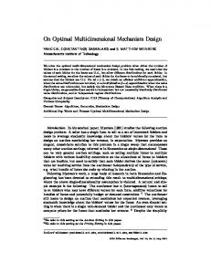
FIGURE 24. (a) The path of indoor positioning test. Red circles mean the positions of Bluetooth beacons for initial localization. Black arrows show the directions of the test path. (b) The strength heat map of magnetic field in the test area. Red area is covered with strong magnetic field strength. Blue area indicates a weak magnetic field strength coverage.
A tester walked along the path shown in Fig.24 (a) with the smartphone in handheld mode. Fig.24 (b) shows the heat map of local magnetic field strength. Red area is covered with strong magnetic field strength. Blue area indicates a weak magnetic field strength coverage. The test area is a typical magnetic field disturbed environment where the magnetic field strength is varying from 32.168uT to 52.244uT due to existing computers, GNSS receivers and simulators, micro oven, LED display, printer, concrete structure, and so on. In the process, the user changed the smartphone placement into calling mode, handswing mode and pocket mode for each walking circle. The total length of each walking cycle is about 300 meters. The result is shown in the Fig.25.
FIGURE 25. Indoor positioning result of multidimensional Particle Filter. The red and black solid blocks are the reference points for positioning. The handheld mode corresponds to the light green trajectory; the calling mode corresponds to the bright blue trajectory; the hand-swing mode and the pocket mode correspond to the dark blue and red trajectories respectively. The start and end points are the same for all trajectories.
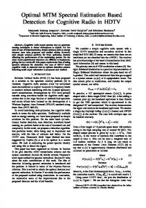
At the same time, we give a schematic particle distribution diagram in the process for this test as shown in Fig.26.
C. FIELD TEST
First, we carried out a positioning test applied with multidimensional particle filter.
2169-3536 (c) 2018 IEEE. Translations and content mining are permitted for academic research only. Personal use is also permitted, but republication/redistribution requires IEEE permission. See http://www.ieee.org/publications_standards/publications/rights/index.html for more information.
This article has been accepted for publication in a future issue of this journal, but has not been fully edited. Content may change prior to final publication. Citation information: DOI 10.1109/ACCESS.2018.2868792, IEEE Access
> REPLACE THIS LINE WITH YOUR PAPER IDENTIFICATION NUMBER (DOUBLE-CLICK HERE TO EDIT) < TABLE V THE TABLE OF INDOOR POSITIONING ERROR OF HEADING ESTIMATION
The particles distribution during the positioning test of Particle Filter
Calling Calling
5000
Handheld Noraml
6000
Handheld Normal
Hand-swing Handswing
Pocket Pocket
Handheld Normal
ASSISTANCE
4000
weight sum
13
th
Item
67 Error Percentile
95th Error Percentile
MPF
0.54m
0.89m
OPF
0.58m 1.52m
1.24m 3.40m
3000
2000
Particles Stable Changed
1000
0
0
50
100
150
200 step count
250
300
350
KF
400
FIGURE 26. The particle distribution during the positioning test of particle filter. The red curve is the weight sum change of the old particle set. The blue curve shows the weight sum change of the particle set after motion changed. The green curve shows the weight sum change of the particle set remaining previous motion.
Furthermore, we carried out the heading estimation optimization test based on multidimensional particle filter. The heading estimation and positioning result is shown in Fig.29.
Moreover, we made a positioning performance comparison test using ordinary particle filter (OPF), and also Kalman filter (KF) under different carrying modes. Fig.27 and Fig.28 shows the OPF positioning results of under hand-swing mode and pocket mode respectively. We can see that the increasing heading estimation error results in the positioning failure because the OPF cannot make a stable and robust heading estimation when the carrying mode changes. The final positioning errors of three filters are shown in Table V.
Reference
Handheld
Calling
Hand-swing
Pocket
FIGURE 29. The result of heading estimation assisted with MPF. The red dashed lines show the reference heading of the test path shown in Fig.24 (a).
FIGURE 27. Indoor positioning result of the ordinary particle filter under hand-swing mode.
FIGURE 30. Underground car park tests with smartphone carrying mode causally changed.
FIGURE 28. Indoor positioning result of the ordinary particle filter under pocket mode.
Last, we carried out challenging tests in an underground car park with 7200m2 using a SAMSUNG Galaxy S6 (Android 6.0.1) to verify the performance of proposed solution in a sparse map constraint environment. The magnetic field of this car park is still suffered from dense concrete pillars and full occupied vehicles. A user walked along a straight line with 45 meters
2169-3536 (c) 2018 IEEE. Translations and content mining are permitted for academic research only. Personal use is also permitted, but republication/redistribution requires IEEE permission. See http://www.ieee.org/publications_standards/publications/rights/index.html for more information.
This article has been accepted for publication in a future issue of this journal, but has not been fully edited. Content may change prior to final publication. Citation information: DOI 10.1109/ACCESS.2018.2868792, IEEE Access
> REPLACE THIS LINE WITH YOUR PAPER IDENTIFICATION NUMBER (DOUBLE-CLICK HERE TO EDIT) < while smartphone carrying mode was causally changed among four carrying modes as shown in Fig. 30. Four test cases show that the proposed solution can handle the scenario of carrying mode change. The transform from/to the hand-swing mode introduces more errors compared to other transforms. Results show that the average error of positioning is less than 2.5 meters with MPF even though in the map-less environment. IV. CONCLUSION
This research paper proposes algorithms focusing on heading estimation and its optimization application on a smartphone platform. The proposed algorithm and suggested magnetometer calibration process can eliminate the influence of magnetic interference in a certain indoor environment range. The heading estimation algorithm using acceleration information makes it possible to achieve accurate heading estimation in different carrying modes and enables various random smartphone handling modes for indoor positioning pedestrians LBS. Moreover, combined with road constraints information, the heading estimation during positioning can correct the heading error effectively. Finally, this paper presents a multidimensional particle filter scheme that combines PDR and motion recognition, which improves positioning accuracy and robustness in addition to optimizing the heading estimation as well. The experimental results show a good performance in both positioning and heading estimation. The challenging tests present a decreased performance. In future, we will introduce the WiFi, Bluetooth, and magnetic field fingerprints into the MPF to achieve a more practical smartphone-based indoor positioning approach. In addition, the more complex carrying mode such as bag mode and more types of smartphone will be further investigated. REFERENCES [1] [2]
http://www.google.com/atap/project-tango/. Visited on June 6, 2018. Serino, M., Cordrey, K., McLaughlin, L., et al. Pokémon Go and augmented virtual reality games: a cautionary commentary for parents and pediatricians. Current opinion in pediatrics, 2016,28(5), 673-677. [3] MAUTZ R. Indoor positioning technologies. Habilitation Thesis, ETH. Zurich, 2012, [4] Ju, Hojin, So Young Park, and Chan Gook Park. A Smartphone-based Pedestrian Dead Reckoning System with Multiple Virtual Tracking for Indoor Navigation. IEEE Sensors Journal (2018). [5] Loomis, J. M., Klatzky, R. L., Golledge, R. G., & Philbeck, J. W. (1999). Human navigation by path integration. Wayfinding behavior: Cognitive mapping and other spatial processes, 125-151. [6] Ladetto, Q. (2000, September). On foot navigation: continuous step calibration using both complementary recursive prediction and adaptive Kalman filtering. In Proceedings of ION GPS (Vol. 2000, pp. 1735-1740) [7] Foxlin, E. (2005). Pedestrian tracking with shoe-mounted inertial sensors. IEEE Computer graphics and applications, 25(6), 38-46. [8] Bahl, P., & Padmanabhan, V. N. (2000). RADAR: An in-building RFbased user location and tracking system. In INFOCOM 2000. Nineteenth Annual Joint Conference of the IEEE Computer and Communications Societies. Proceedings. IEEE (Vol. 2, pp. 775-784).. [9] Hallberg, J., Nilsson, M., & Synnes, K. (2003, March). Positioning with bluetooth. In Telecommunications, 2003. ICT 2003. 10th International Conference on (Vol. 2, pp. 954-958). IEEE. [10] Storms, W. F. (2009). Magnetic field aided indoor navigation (No. AFIT/GE/ENG/09-44). Air Force Institute of Tech Wright-Patterson AFB Oh Graduate School of Engineering and Management. [11] Mulloni A, Wagner D, Barakonyi I, et al. Indoor Positioning and Navigation with Camera Phones. IEEE Pervasive Computing, 2009, 8(2):22-31.
14
[12] Kim J W, Han J J, Hwang D H, et al. A step, stride and heading determination for the pedestrian navigation system. Positioning, 2004, 3(1&2):273-279. [13] Yuan X, Shuai Y, Zhang S, et al. Quaternion-Based Unscented Kalman Filter for Accurate Indoor Heading Estimation Using Wearable MultiSensor System. Sensors, 2015, 15(5):10872. [14] Motwani A, Liu W, Sharma S, et al. An interval Kalman filter-based fuzzy multi-sensor fusion approach for fault-tolerant heading estimation of an autonomous surface vehicle. Proceedings of the Institution of Mechanical Engineers Part M Journal of Engineering for the Maritime Environment, 2016, 6(22):222-230. [15] Chen W, Chen R, Chen Y, et al. An effective Pedestrian Dead Reckoning algorithm using a unified heading error model. Position Location and Navigation Symposium. IEEE, 2010:340-347. [16] Kang W, Han Y. SmartPDR: Smartphone-Based Pedestrian Dead Reckoning for Indoor Localization. IEEE Sensors Journal, 2015, 15(5):2906-2916. [17] Kang W, Nam S, Han Y, et al. Improved heading estimation for smartphone-based indoor positioning systems. IEEE, International Symposium on Personal Indoor and Mobile Radio Communications. IEEE, 2012:2449-2453. [18] Blanke U. Sensing location in the pocket. Quarterly Journal of Experimental Psychology, 2008, 19(1):54-58. [19] Delaloye C, Baudois S, Bilbao F D, et al. Dead reckoning from the pocket - An experimental study. IEEE International Conference on Pervasive Computing and Communications. IEEE, 2010:162-170. [20] Kai K, Lukowicz P, Partridge K, et al. Which Way Am I Facing: Inferring Horizontal Device Orientation from an Accelerometer Signal. International Symposium on Wearable Computers. IEEE, 2009:149-150. [21] Deng Z A, Wang G, Hu Y, et al. Heading Estimation for Indoor Pedestrian Navigation Using a Smartphone in the Pocket. Sensors, 2015, 15(9):21518-21536. [22] Deng, Zhian, Xin Liu, Zhiyu Qu, Changbo Hou, and Weijian Si. Robust Heading Estimation for Indoor Pedestrian Navigation Using Unconstrained Smartphones. Wireless Communications and Mobile Computing. (2018). [23] Xiao Z, Wen H, Markham A, et al. Robust pedestrian dead reckoning (RPDR) for arbitrary mobile device placement. International Conference on Indoor Positioning and Indoor Navigation. IEEE, 2015:187-196. [24] Qiu, S., Wang, Z., Zhao, H., Qin, K., Li, Z., & Hu, H. Inertial/magnetic sensors based pedestrian dead reckoning by means of multi-sensor fusion. Information Fusion, 2018, 39: 108-119. [25] Li, Y., Zhuang, Y., Zhang, P., Lan, H., Niu, X., & El-Sheimy, N. An improved inertial/wifi/magnetic fusion structure for indoor navigation. Information Fusion, 2017,34:101-119. [26] Harle, R. (2013). A survey of indoor inertial positioning systems for pedestrians. IEEE Communications Surveys and Tutorials, 15(3), 12811293. [27] Kwon W, Roh K S, Sung H K. Particle filter-based heading estimation using magnetic compasses for mobile robot navigation. IEEE International Conference on Robotics and Automation. IEEE, 2006:27052712. [28] Calibrate your compass: figure 8 pattern method. https://calibratecompass.com/. Visited on June 6, 2018. [29] Lin Wang, Zhenjiang Dong, Ling Pei, Jiuchao Qian, Chengxuan Liu, Donghui Lu, Peilin Liu A robust context-based heading estimation algorithm for pedestrian using a smartphone. (2015). Proceedings of the 28th international technical meeting of the satellite division of the institute of navigation (ION GNSS 2015). Tampa, FL USA, SEP 14-18, 2015. [30] Chao M, Jiang D, Wen C. Error Analysis and Calibration of Magnetic Compass. Chinses Journal of Sensors and Actuators, 2010, 23(4). [31] Afzal M H. Use of Earth's Magnetic Field for Pedestrian Navigation. Dissertation Abstracts International, 2011, 73(05). [32] Afzal M H, Renaudin V, Lachapelle G. Magnetic field based heading estimation for pedestrian navigation environments. Indoor Positioning and Indoor Navigation (IPIN), 2011 International Conference on. IEEE, 2011:1-10. [33] Merayo J M G, Brauer P, Primdahl F, et al. Scalar Calibration of Vector Magnetometers. Measurement Science & Technology, 2000, 11(2):120132(13). [34] Fang J, Sun H, Cao J, et al. A Novel Calibration Method of Magnetic Compass Based on Ellipsoid Fitting. Instrumentation & Measurement IEEE Transaction on, 2011, 60:2053-2061. [35] Ozyagcilar, Talat. Calibrating an ecompass in the presence of hard and soft-iron interference. Freescale Semiconductor Ltd (2012): 1-17.
2169-3536 (c) 2018 IEEE. Translations and content mining are permitted for academic research only. Personal use is also permitted, but republication/redistribution requires IEEE permission. See http://www.ieee.org/publications_standards/publications/rights/index.html for more information.
This article has been accepted for publication in a future issue of this journal, but has not been fully edited. Content may change prior to final publication. Citation information: DOI 10.1109/ACCESS.2018.2868792, IEEE Access
> REPLACE THIS LINE WITH YOUR PAPER IDENTIFICATION NUMBER (DOUBLE-CLICK HERE TO EDIT) < [36] Liu D, Pei L, Qian J, et al. Simplified Ellipsoid Fitting-Based Magnetometer Calibration for Pedestrian Dead Reckoning. China Satellite Navigation Conference (CSNC) 2016 Proceedings: Volume II. Springer Singapore, 2016. [37] Qian J, Pei L, Ma J, et al. Vector Graph Assisted Pedestrian Dead Reckoning Using an Unconstrained Smartphone. Sensors, 2015, 15(3):5032. [38] Madgwick, S. An efficient orientation filter for inertial and inertial/magnetic sensor arrays. Report x-io and University of Bristol (UK) (2010). [39] Liu, D., Pei, L., Qian, J., et al. A novel heading estimation algorithm for pedestrian using a smartphone without attitude constraints. In Ubiquitous Positioning, Indoor Navigation and Location Based Services (UPINLBS), Fourth International Conference on, 2016, pp. 29-37. [40] A. Perttula, H. Leppäkoski, M. Kirkko-Jaakkola, P. Davidson, J. Collin and J. Takala, Distributed Indoor Positioning System with Inertial Measurements and Map Matching, in IEEE Transactions on Instrumentation and Measurement, 2014, 63(11): 2682-2695. [41] Shin H, Chon Y, Cha H. Unsupervised construction of an indoor floor plan using a smartphone. IEEE Transactions on Systems, Man, and Cybernetics, Part C (Applications and Reviews), 2012, 42(6): 889-898. [42] Abdulrahim, Khairi, et al. Integrating low cost IMU with building heading in indoor pedestrian navigation. Journal of Global Positioning Systems, 2011,10 (1): 30-38. [43] Link, J. A. B., Smith, P., Viol, N., & Wehrle, K. (2011, September). Footpath: Accurate map-based indoor navigation using smartphones. In Indoor Positioning and Indoor Navigation (IPIN), 2011 International Conference on (pp. 1-8). IEEE. [44] Yang J, Wang R S. Classified road detection from satellite images based on perceptual organization. International Journal of Remote Sensing, 2007, 28(20):4653-4669. [45] Rianto Y, Kim T, Kondo S. Detection of roads from satellite image using optimal search. Circuits and Systems, 1998. IEEE APCCAS 1998. The 1998 IEEE Asia-Pacific Conference on. IEEE, 2000:587-590. [46] Ameri F, Mobaraki A M, Zoej M J V. Semi-Automatic Extraction Of Different-Shaped Road Centerlines From Ms And Pan-Sharpend Ikonos Images. Georgia Historical Quarterly, 2010(2):234-235. [47] Beauregard S, Widyawan, Klepal M. Indoor PDR performance enhancement using minimal map information and particle filters. Position, Location and Navigation Symposium, 2008 IEEE/ION. IEEE, 2008:141147. [48] Doucet A, Johansen A M. A Tutorial on Particle Filtering and Smoothing: Fifteen Years Later. In Handbook of Nonlinear Filtering (eds, 2011, 12. [49] Murray L M, Lee A, Jacob P E. Rethinking resampling in the particle filter on graphics processing units. Eprint Arxiv, 2013. [50] Antonio F. Faster line segment intersection. Graphics Gems III. Academic Press Professional, Inc. 1992:199-202. LING PEI received the Ph.D. degree from Southeast University, Nanjing, China, in 2007.From 2007 to 2013, he was a Specialist Research Scientist with the Finnish Geospatial Research Institute. He is currently an Associate Professor with the School of Electronic Information and Electrical Engineering, Shanghai Jiao Tong University. He has authored or coauthored over 90 scientific papers. He is also an inventor of 24 patents and pending patents. His main research is in the areas of indoor/outdoor seamless positioning, ubiquitous computing, wireless positioning, Bioinspired navigation, context-aware applications, location-based services, and navigation of unmanned systems. Dr. Pei was a recipient of the Shanghai Pujiang Talent in 2014.
15
DANPING ZOU received the B.S. degree from Huazhong University of Science and Technology, Wuhan, China, and the Ph.D. degree from Fudan University, Shanghai, China, in 2003 and 2010, respectively. From 2010 to 2013, he was a Research Fellow with the Department of Electrical and Computer Engineering, National University of Singapore, Singapore. In 2013, he joined the Department of Electronic Engineering, Shanghai Jiao Tong University, Shanghai, as an Associate Professor. His research interests include low-level 3-D vision on robotics. YUWEI CHEN received B.E. and M.Sc degree from Department of Information Science and Electronics Engineering Zhejiang University, China, in 1999 and 2002 respectively and Ph.D. degree in Circuits and Systems from Shanghai Institute of Technical Physics, Chinese Academy of Science in 2005. He is now working in the Finnish Geospatial Research Institute as a research manager leads the research group “remote sensing electronics”, which focuses on developing new remote sensing systems. He is also a guest professor of Academy of OptoElectronics, Chinese Academy of Science. He holds 10 patents and has authored and co-authored more than 100 scientific papers and book chapters. His research interests include LiDAR, hyperspectral LiDAR, radar, and navigation and positioning. RONALD LEE FOOK CHOY received the B.S. degree in electrical engineering from McGill University, Montrreal Canada, in 2003. He is currently the machine learning test director at Shanghai BeiDou Research Institute, with responsibilities to build the biggest robotics test and training facility in China. His research focuses on benchmarking autonomous machines performance based on GNC applications with special interest on stereo vision, ToF vision, LiDAR vision and data fusion to achieve indoor/outdoor positioning and navigation.
ZHE HE received his B.S. and M.S. degrees in Shanghai Jiao Tong University, majoring in Navigation Guidance and Control, and Ph.D. degree in Geomatics Engineering in University of Calgary in Canada. He worked as a postdoctoral fellow in the Position, Location And Navigation (PLAN) Group in the Department of Geomatics Engineering at the University of Calgary and is director of technology of a startup company in Calgary, focusing on LPWAN and LBS. His research interests are statistical estimation theory applied to GNSS, inertial and integrated navigation systems, low power wide area networks LBS systems.
DONGHUI LIU received the B.S. degree in electrical engineering from Shanghai Jiao Tong University, Shanghai, China, in 2016, where he is currently working toward the Master’s degree with the Shanghai Key Laboratory of Navigation and Location-based Services. His main research is in the areas of indoor/outdoor seamless positioning, ubiquitous computing, wireless positioning, Pedestrian Dead Reckoning. He received the Best Youth Talent Paper Award of CSNC 2016.
2169-3536 (c) 2018 IEEE. Translations and content mining are permitted for academic research only. Personal use is also permitted, but republication/redistribution requires IEEE permission. See http://www.ieee.org/publications_standards/publications/rights/index.html for more information.